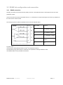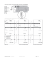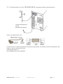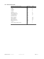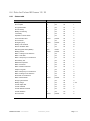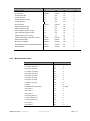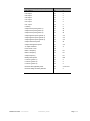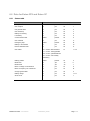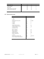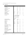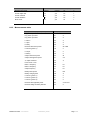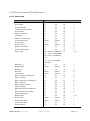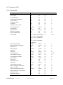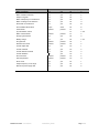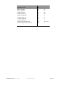
1
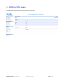
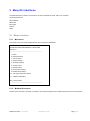
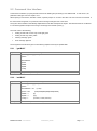
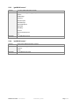
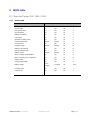
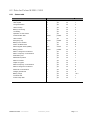
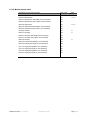
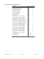
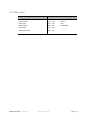
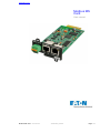
www.eaton.com Modbus MS Card User manual Modbus MS Card – User Manual 34009048XT_EN/AD Page 1/55 Contents 1 INTRODUCTION 4 2 PRESENTATION 5 2.1 OVERVIEW 5 2.2 FUNCTIONS 5 2.3 TECHNICAL CHARACTERISTICS 6 3 INSTALLATION 7 3.1 RS232 LINK CONFIGURATION AND CONNECTION 7 3.2 RS485 LINK CONFIGURATION AND CONNECTION 8 3.2.1 RS485 connection 8 3.2.2 RS485 link configuration for 2 wires connexion 10 3.2.3 RS485 link configuration for 4 wires connexion 12 3.3 CONFIGURATION OF THE JBUS/MODBUS COMMUNICATION PARAMETERS 14 3.3.1 Choice 1: Display Jbus settings 15 3.3.2 Choice 2: Modify Jbus settings 15 3.3.3 Choice 3: Display Jbus diagnostics 16 3.3.4 Choice 4: Reset Jbus diagnostics 16 3.3.5 Choice 5: Return to Jbus Default Configuration 16 3.3.6 Choice 6: Display Jbus frames 16 4 ADDITIONAL WEB PAGES 18 5 MENU/CLI INTERFACES 19 5.1 MENU INTERFACE 5.1.1 Main menu 19 5.1.2 Modbus/Jbus menu 19 5.2 COMMAND LINE INTERFACE 21 5.2.1 “getJBUS” 21 5.2.2 “setJBUS” 21 5.2.3 “getJBUSCounter” 22 5.2.4 “setJBUSCounter” 22 6 JBUS TABLE 6.1 23 DATA FOR PULSAR 700 / 1000 / 1500 23 6.1.1 Status table 23 6.1.2 Measurements table 24 6.2 DATA FOR PULSAR M 2200 / 3000 25 6.2.1 Status table 25 6.2.2 Measurements table 26 6.3 6.4 19 DATA FOR PULSAR MX 4000 / 5000 / 10000 27 6.3.1 Status table 27 6.3.2 Measurements table 28 DATA FOR PULSAR MX FRAME 15 / 20 Modbus MS Card – User Manual 34009048XT_EN/AD 29 Page 2/55 6.4.1 Status table 29 6.4.2 Modular fault table 30 Measurements table 32 6.4.3 6.5 DATA FOR EATON 93E AND EATON 93PM 6.5.1 Status table 34 6.5.2 Measurements table 35 6.6 DATA FOR EATON 5PX AND EATON 5P Status table 37 6.6.2 Measurements table 38 DATA FOR EATON 9E 39 6.7.1 Status table 39 6.7.2 Measurements table 40 6.8 DATA FOR EATON 9PX AND EATON 9SX SINGLE PHASE 41 6.8.1 Status table 41 6.8.2 Measurements table 42 6.9 DATA FOR EATON 9PX THREE PHASE INPUT 43 6.9.1 Status table 43 6.9.2 Measurements table 44 6.10 DATA FOR EATON 9PX SPLIT PHASE 45 6.10.1 Status table 45 6.10.2 Measurements table 46 6.11 GENERIC UPS 47 6.11.1 Status table 47 6.11.2 Measurements table 49 6.12 SENSOR DATA 51 6.12.1 Status table 51 6.12.2 Measurements table 52 Read of the personalization table 53 6.12.3 7 37 6.6.1 6.7 6.13 34 OTHER DATA 54 GLOSSARY Modbus MS Card – User Manual 55 34009048XT_EN/AD Page 3/55 1 Introduction The embedded application of the Modbus MS Card (previously INMC) is based on the Network MS Card (previously NMC). For all common features, the user manual is the same as NMC (see reference below). In this document, only JBUS/MODBUS requirements are described. Reference Network Management Card – User Manual 34003990XT_FR/EF Modbus MS Card – User Manual 34009048XT_EN/AD Page 4/55 2 Presentation 2.1 Overview 2.2 Functions The Modbus MS Card provides the same functions than the Network MS card described in the previous section of this document. The adding function consists to provide UPS (Uninterruptible Power Supply) data (states and measures) to be sent a computer system. The JBUS hexadecimal (MODBUS RTU) communication protocol is used in slave mode. The system provides a communication channel with an RS485 or RS232 interface. Note: 2 wires or 4 wires RS485 link are available. Warning: RS232 and RS485 communication ports cannot be used together. JBUS/MODBUS communication is operational 2 minutes after the startup of the card. Modbus MS Card – User Manual 34009048XT_EN/AD Page 5/55 2.3 Technical characteristics Functions Parameters Default values Possible values JBUS/MODBUS - Baud rate - 9600 bauds - 1200, 2400, 4800, 9600, 19200, 38400 communication - Parity - without parity - Without parity, even parity, odd parity - Bit number -8 - - Stop bit -2 - 1, 2 - Slave number - Slave nr 1 - 1 to FF (hexadecimal) - Link connection in - Rx on pin 1 - Rx on pin 1 transmit data (Tx) or - Tx on pin 3 - Tx on pin 3 - No termination - With or without (2 or 4 wires) RS232 link receive data (Rx) RS485 link - Termination Modbus MS Card – User Manual 34009048XT_EN/AD Page 6/55 3 Installation 3.1 RS232 link configuration and connection Set the SA2 switches like below: The next figure shows the details of the connection in RS232 mode: Pin number Function 1 Received data (input) 2 Not connected JBUS/232/485 ETHERNET Settings/Sensor Tx Rx OV T+ T- R+ R- ACT 100M UPS Data RS232 XXXXXXXXXXXX 66103 3 5 4 3 Modbus MS Card – User Manual 2 1 34009048XT_EN/AD Transmitted data (output) 4 Not connected 5 Signal Ground Page 7/55 3.2 RS485 link configuration and connection 3.2.1 RS485 connection Normally, the master of the network sets the polarity of the line. The Modbus MS card is a slave equipment and don’t have polarisation resistor. The two ends of the line must be terminated. Allow for 1 or 2 terminators to avoid mismatching the line when any equipment at the end of the line is disconnected. The next figure gives the detail of the RS485 connector and the internals drivers: Pin number Function 1 R- : Receiver - (input) 2 R+ : Receiver + (input) 3 T- : Transmitter - (output) 4 5 T+ : Transmitter + (output) 0V Important notes: 2 Use twisted pair cable (cable specification 0.3mm and capacitance 42pF/m) The transmission range will increase if a cable with lower capacitance and larger diameter is used. Use shielded cable in heavy industrial environments. Modbus MS Card – User Manual 34009048XT_EN/AD Page 8/55 The settings of the RS485 link are made through the SA1 switches: SA1 description: 1: reserved 2: reserved 3: link termination between T- to R- (2 wires configuration) if set to ON 4: connection T- to R- (2 wires configuration) if set to ON 5: connection T+ to R+ (2 wires configuration) if set to ON 6: reserved 7: reserved 8: link termination between R+ and R- if set to ON Modbus MS Card – User Manual 34009048XT_EN/AD Page 9/55 3.2.2 RS485 link configuration for 2 wires connexion Set the SA2 switches like below to set the RS485 mode: Set the SA1 switches to select the two wires configuration with no termination: Modbus MS Card – User Manual 34009048XT_EN/AD Page 10/55 Set the SA1 switches to select the two wires configuration with termination: The next figure gives a typical bus structure in the two wires configuration: Modbus MS Card – User Manual 34009048XT_EN/AD Page 11/55 3.2.3 RS485 link configuration for 4 wires connexion Set the SA2 switches like below: Set the SA1 switches to select the four wires configuration with no termination: Modbus MS Card – User Manual 34009048XT_EN/AD Page 12/55 Set the SA1 switches to select the four wires configuration with termination: The next figure gives a typical bus structure in the four wires configuration: Modbus MS Card – User Manual 34009048XT_EN/AD Page 13/55 3.3 Configuration of the JBUS/MODBUS communication parameters Connect the RS232 link to a terminal (Microsoft Hyper terminal) Use the cord supplied with the card. Connect the card to a computer equipped with a Hyper terminal type emulator. The serial link must be set at 9600 baud, 8 bits, no parity, 1 stop bit, and without flow control. Check that UPS power is on. Enter the admin password (not upgradable). Modbus MS Card – User Manual 34009048XT_EN/AD Page 14/55 The next menu appears: ----------------------------------------------------------------------------EATON NETWORK MANAGEMENT – JBUS CARD ----------------------------------------------------------------------------1 : Reset 2 : Network configuration 3 : Set Login Password to Default 4 : Return to Default Configuration 5 : Jbus configuration 6 : Sensor configuration 0 : Exit ----------------------------------------------------------------------------- Type 5 and return to display the JBUS configuration menu. The next menu appears: ----------------------------------------------------------------------------Jbus settings ----------------------------------------------------------------------------1 : Display Jbus settings 2 : Modify Jbus settings 3 : Display Jbus diagnostics 4 : Reset Jbus diagnostics 5 : Return to Jbus Default Configuration 6 : Display Jbus frames 0 : Exit ----------------------------------------------------------------------------- 3.3.1 Choice 1: Display Jbus settings Enables reading of the card's Jbus settings Jbus configuration : Slave number : 1 Speed : 9600 bds Data : 8 bits stop bit : 1 Parity : None 3.3.2 Choice 2: Modify Jbus settings Enable the modification of Jbus settings. Modbus MS Card – User Manual 34009048XT_EN/AD Page 15/55 Setting Jbus configuration : Set Slave number : 0x1 Set the Baud Rate [1: 38400, 2: 19200, 3: 9600, 4: 4800, 5: 2400, 6: 1200] :3 Set data format [1: 8 bits] :1 Set stop bit [1: 1 bits, 2: 2 bits] :1 Set Parity [1: None, 2: Even, 3: Odd] :1 Wait during the new configuration is saved ... Slave JBUS initialized The Jbus configuration is now updated. 3.3.3 Choice 3: Display Jbus diagnostics Enable reading of the Jbus diagnostics. Jbus diagnostics : Cpt1 - Bus Message Count:0 Cpt2 - CRC Error Count :0 Cpt3 - Slave Exception Error Count:0 Cpt4 - Slave Message Count:0 Cpt5 - Slave No Response Count:0 Cpt6 - Slave NAK Count:0 Cpt7 - Slave Busy Count:0 Cpt8 - Bus Caracter Overrun Count:0 Cpt9 - Slave Correct Response Count:0 3.3.4 Choice 4: Reset Jbus diagnostics Reset the Jbus diagnostic counters. 3.3.5 Choice 5: Return to Jbus Default Configuration Returns to the Jbus default configuration (0x01, 9600, 8, 1, none) Wait during Jbus configuration returns to default ... Jbus Configuration has been set to default one. 3.3.6 Choice 6: Display Jbus frames Enable the display of the Jbus frames: Modbus MS Card – User Manual 34009048XT_EN/AD Page 16/55 Recv : 01 01 00 00 00 64 3d e1 Send : 01 81 02 c1 91 Recv : 01 03 00 62 00 64 e5 ff Send : 01 03 c8 00 00 00 00 00 00 00 00 00 00 00 00 00 ... Recv : 01 01 00 00 00 64 3d e1 Send : 01 81 02 c1 91 Recv : 01 03 00 62 00 64 e5 ff Send : 01 03 c8 00 00 00 00 00 00 00 00 00 00 00 00 00 ... Modbus MS Card – User Manual 34009048XT_EN/AD Page 17/55 4 Additional Web pages The Modbus MS card parameters could be set through the next page: Modbus MS Card – User Manual 34009048XT_EN/AD Page 18/55 5 Menu/CLI interfaces The parameters links to JBUS communication are also accessible via Telnet, SSH or CLI interface. Those parameters are: Slave address Bauds rate Bit number Stop bit Parity 5.1 Menu interface 5.1.1 Main menu This screen is the main screen displayed when the connection is established. -----------------------------------------------------------------------EATON NETWORK MANAGEMENT- JBUS CARD Main menu -----------------------------------------------------------------------1 : Reset 2 : Network settings 3 : Trap receivers 4 : System settings 5 : Shutdown settings 6 : Access control 7 : Date and Time 8 : Environment settings 9 : Modbus/Jbus settings 10 : Set login password to default 11 : Default configuration Quit : Close session ------------------------------------------------------------------------ 5.1.2 Modbus/Jbus menu Theses menus are used to visualize or modify the Jbus network settings and to visualize the status of the communication. Modbus MS Card – User Manual 34009048XT_EN/AD Page 19/55 -----------------------------------------------------------------------EATON NETWORK MANAGEMENT - JBUS CARD Modbus/Jbus settings -----------------------------------------------------------------------1 : Serial link 2 : Diagnostic counters 0 : Exit ---------------------------------------------------------------------- -----------------------------------------------------------------------EATON NETWORK MANAGEMENT - JBUS CARD Modbus/Jbus settings – Serial link -----------------------------------------------------------------------1 : Slave address [1] 2 : Baud rate (1200, 2400, 4800, 9600, 19200, 38400) [9600] 3 : Data bits (8) [8] 4 : Stop bits (1, 2) [1] 5 : Parity (0=None, 1=Odd, 2=Even) [0] 0 : Exit ---------------------------------------------------------------------- -----------------------------------------------------------------------EATON NETWORK MANAGEMENT - JBUS CARD Modbus/Jbus settings – Serial link -----------------------------------------------------------------------: Buss message [24] : CRC error [0] : Slave exception error [0] : Slave message [24] : Slave no response [0] : Slave NAK [0] : Slave busy [0] : Bus character overrun [0] : Slave correct response [0] 10 : Reset diagnostic counter 0 : Exit ---------------------------------------------------------------------All items (1 à 9) are read only. Modbus MS Card – User Manual 34009048XT_EN/AD Page 20/55 5.2 Command Line Interface Command Line Interface (CLI) API provides functions for building and processing a user-defined HMI. To use the CLI, the parameter “HMI type” has to be equal to “CLI”. When opening a new session, TELNET or SSH, a specific prompt “#>” is sent to the client. The user can enter a command. If the command is recognized, it is processed, else a warning message is sent to the client. The syntax used is based on that already implemented for the XML description of objects. The blank character is not allowed in command arguments except for the strings. The strings are in double quotes (“”). The code colour is the following: Setting in read-write or write-only mode: light green Setting in read-only mode: yellow Warning message: green Error message: light red The recognized commands are given in the following chapters and may be updated later. 5.2.1 “getJBUS” Purpose To read a JBUS network setting Syntax getJBUS [option1] [option2]... options : SlaveAddress Speed DataBit StopBit Parity Examples 5.2.2 #> getJBUS Speed Parity “setJBUS” Purpose To modify a JBUS network setting Syntax setJBUS [option1] [option2]... options : SlaveAddress = xxx Speed = xxxx (1200|2400|4800|9600|19200|38400) DataBit = x (8) StopBit = x (1|2) Parity = x Examples (1..255) (0=None, 1=Odd, 2=Even) #> setJBUS Speed = 19200 Parity = 2 Modbus MS Card – User Manual 34009048XT_EN/AD Page 21/55 5.2.3 “getJBUSCounter” Purpose To read a JBUS diagnostic counters Syntax getJBUSCounter [option1] [option2]... options : BusMessage CRCError SlaveException SlaveMessage SlaveNoResponse SlaveNAK SlaveBusy Overrun SlaveCorrectResponse All Examples 5.2.4 #> getJBUSCounter All “setJBUSCounter” Purpose Reset of the JBUS diagnostics counters Syntax setJBUSCounter [option1] options : RAZ Examples #> setJBUSCounter RAZ Modbus MS Card – User Manual 34009048XT_EN/AD Page 22/55 6 JBUS table 6.1 Data for Pulsar 700 / 1000 / 1500 6.1.1 Status table Status description Status to 0 Status to 1 Word (hex) Bit Load protected no yes 40 0 UPS coupled no yes 40 1 Unit general alarm no yes 40 2 UPS in backup no yes 40 4 Battery low warning no yes 40 5 Low battery no yes 40 6 Operation on static switch no yes 40 7 Communication fault absent present 40 9 UPS overload no yes 40 A Emergency stop absent present 40 B Battery to be checked no yes 40 D Device ventilation fault no yes 40 E Battery present absent present 42 0 Mains 1 voltage out of tolerance no yes 44 8 Mains 1 frequency out of tolerance no yes 44 B Bypass status no yes 46 7 Charger general fault no yes 49 0 in charge 49 1&3 Battery charge not in charge Converter fault no yes 4A 1 Inverter fault no yes 4C 1 Modbus MS Card – User Manual 34009048XT_EN/AD Page 23/55 6.1.2 Measurements table Description of the physical quantity Word (hex) Unit I output 109 A U output 124 V U battery 12D V Output active power 136 W Output apparent power 137 VA % output load level 139 % Power factor (Cos PHI) 13D - Mains 1 frequency 13E Hz Output frequency 141 Hz Battery backup time 149 Min Battery charging level 14B % U mains 1 150 V Nominal voltage of battery element 213 V Modbus MS Card – User Manual 34009048XT_EN/AD Page 24/55 6.2 Data for Pulsar M 2200 / 3000 6.2.1 Status table Status description Status to 0 Status to 1 Word (hex) Bit Load protected no yes 40 0 UPS coupled no yes 40 1 Unit general alarm no yes 40 2 UPS in backup no yes 40 4 Battery low warning no yes 40 5 Low battery no yes 40 6 Operation on static switch no yes 40 7 Communication fault absent present 40 9 UPS overload no yes 40 A Emergency stop absent present 40 B Battery to be checked no yes 40 D Device ventilation fault no yes 40 E Manual bypass switch (Q3BP) open closed 41 6 Battery present absent present 42 0 Mains 1 voltage out of tolerance no yes 44 8 Mains 1 frequency out of tolerance no yes 44 B Redundancy lost no yes 45 7 Maintenance position no yes 46 1 Mains 2 overload no yes 46 5 Output on bypass no yes 46 7 Mains 2 frequency out of tolerance no yes 46 9 Mains 2 voltage out of tolerance no yes 46 A Phase M2 out of tolerance no yes 46 B Charger general fault no yes 49 0 Battery charge no yes 49 1&3 Converter fault no yes 4A 1 Inverter major fault no yes 4C 1 Modbus MS Card – User Manual 34009048XT_EN/AD Page 25/55 6.2.2 Measurements table Description of the physical quantity Word (hex) Unit I mains 2 106 A I output 109 A U mains 2 11E V U output 124 V U battery 12D V Output active power 136 W Output apparent power 137 VA % output load level 139 % Power factor x 100 13D - Mains 1 frequency 13E dHz Output frequency 141 dHz Battery backup time 149 Min Battery charging level 14B % U mains 1 150 V Nominal voltage of battery element 213 V Modbus MS Card – User Manual 34009048XT_EN/AD Page 26/55 6.3 Data for Pulsar MX 4000 / 5000 / 10000 6.3.1 Status table Status description Status to 0 Status to 1 Word (hex) Bit Load protected no yes 40 0 UPS coupled no yes 40 1 Unit general alarm no yes 40 2 UPS in backup no yes 40 4 Battery low warning no yes 40 5 Low battery no yes 40 6 Operation on static switch no yes 40 7 Communication fault absent present 40 9 UPS overload no yes 40 A Emergency stop absent present 40 B Battery to be checked no yes 40 D Device ventilation fault no yes 40 E Manual bypass switch (Q3BP) open closed 41 6 UPS in “eco” mode no yes 41 7 Battery present absent present 42 0 Mains 1 voltage out of tolerance no yes 44 8 Mains 1 fuse fault no yes 44 9 Mains 1 frequency out of tolerance no yes 44 B Redundancy lost no yes 45 7 Maintenance position no yes 46 1 Mains 2 overload no yes 46 5 Mains 2 thermal overload no yes 46 6 Output on bypass no yes 46 7 Mains 2 frequency out of tolerance no yes 46 9 Mains 2 voltage out of tolerance no yes 46 A Phase M2 out of tolerance no yes 46 B Mains 2 internal fault absent present 47 2 Charger general fault no yes 49 0 Battery charge no yes 49 1&3 Converter fault no yes 4A 1 Inverter major fault no yes 4C 1 Inverter overload no yes 4C 2 Inverter thermal overload no yes 4C 3 Inverter limitation no yes 4C 4 UPS fuse fault absent present 4C 5 Modbus MS Card – User Manual 34009048XT_EN/AD Page 27/55 6.3.2 Measurements table Description of the physical quantity Word (hex) Unit I mains 1 100 A I mains 2 106 A I output 109 A I battery 10E A U mains 2 11E V U output 124 V U battery 12D V Output active power 136 W Output apparent power 137 VA % output load level 139 % Power factor (Cos PHI) 13D - Mains 1 frequency 13E dHz Mains 2 frequency 140 dHz Output frequency 141 dHz Battery backup time 149 Min Battery charging level 14B % U mains 1 150 V Nominal voltage of battery element 213 V Modbus MS Card – User Manual 34009048XT_EN/AD Page 28/55 6.4 Data for Pulsar MX frame 15 / 20 6.4.1 Status table Status description Status to 0 Status to 1 Word (hex) Bit Load protected no yes 40 0 UPS coupled no yes 40 1 Unit general alarm no yes 40 2 UPS in backup no yes 40 4 Battery low warning no yes 40 5 Low battery no yes 40 6 Operation on static switch no yes 40 7 Communication fault absent present 40 9 UPS overload no yes 40 A Emergency stop absent present 40 B Battery to be checked no yes 40 D Device ventilation fault no yes 40 E Manual bypass switch (Q3BP) open closed 41 6 Battery present absent present 42 0 Mains 1 voltage out of tolerance no yes 44 8 Mains 1 fuse fault no yes 44 9 Mains 1 frequency out of tolerance no yes 44 B Redundancy lost no yes 45 7 Maintenance position no yes 46 1 Mains 2 overload no yes 46 5 Mains 2 thermal overload no yes 46 6 Output on bypass no yes 46 7 Mains 2 frequency out of tolerance no yes 46 9 Mains 2 voltage out of tolerance no yes 46 A Phase M2 out of tolerance no yes 46 B Mains 2 internal fault absent present 47 2 Charger general fault no yes 49 0 Battery charge no yes 49 1&3 Inverter major fault no yes 4C 1 Inverter overload no yes 4C 2 Inverter thermal overload no yes 4C 3 Inverter limitation no yes 4C 4 UPS fuse fault absent present 4C 5 Modbus MS Card – User Manual 34009048XT_EN/AD Page 29/55 6.4.2 Modular fault table Description du Status Status to 0 Status to 1 Word Bit (hex) Module 1 Module 2 Module 3 Module 4 General alarm Absent Present 61 0 Fan failure Absent Present 61 1 Internal communication fault Absent Present 61 2 Inverter thermal overload Absent Present 61 3 Inverter fault Absent Present 61 4 Inverter fuse blown Absent Present 61 5 Load short circuit Absent Present 61 6 General alarm Absent Present 62 0 Fan failure Absent Present 62 1 Internal communication fault Absent Present 62 2 Inverter thermal overload Absent Present 62 3 Inverter fault Absent Present 62 4 Inverter fuse blown Absent Present 62 5 Load short circuit Absent Present 62 6 General alarm Absent Present 63 0 Fan failure Absent Present 63 1 Internal communication fault Absent Present 63 2 Inverter thermal overload Absent Present 63 3 Inverter fault Absent Present 63 4 Inverter fuse blown Absent Present 63 5 Load short circuit Absent Present 63 6 General alarm Absent Present 64 0 Fan failure Absent Present 64 1 Internal communication fault Absent Present 64 2 Inverter thermal overload Absent Present 64 3 Inverter fault Absent Present 64 4 Inverter fuse blown Absent Present 64 5 Load short circuit Absent Present 64 6 Modbus MS Card – User Manual 34009048XT_EN/AD Page 30/55 Description du Status Status to 0 Status to 1 Word Bit (hex) Module 5 Module 6 Module 7 Module 8 General alarm Absent Present 65 0 Fan failure Absent Present 65 1 Internal communication fault Absent Present 65 2 Inverter thermal overload Absent Present 65 3 Inverter fault Absent Present 65 4 Inverter fuse blown Absent Present 65 5 Load short circuit Absent Present 65 6 General alarm Absent Present 66 0 Fan failure Absent Present 66 1 Internal communication fault Absent Present 66 2 Inverter thermal overload Absent Present 66 3 Inverter fault Absent Present 66 4 Inverter fuse blown Absent Present 66 5 Load short circuit Absent Present 66 6 General alarm Absent Present 67 0 Fan failure Absent Present 67 1 Internal communication fault Absent Present 67 2 Inverter thermal overload Absent Present 67 3 Inverter fault Absent Present 67 4 Inverter fuse blown Absent Present 67 5 Load short circuit Absent Present 67 6 General alarm Absent Present 68 0 Fan failure Absent Present 68 1 Internal communication fault Absent Present 68 2 Inverter thermal overload Absent Present 68 3 Inverter fault Absent Present 68 4 Inverter fuse blown Absent Present 68 5 Load short circuit Absent Present 68 6 Modbus MS Card – User Manual 34009048XT_EN/AD Page 31/55 6.4.3 Measurements table Description of the physical quantity Word (hex) Unit I1 (I phase 1) mains 1 100 A I2 (I phase 2) mains 1 101 A I3 (I phase 3) mains 1 102 A I1 (I phase 1) mains 2 106 A I2 (I phase 2) mains 2 107 A I3 (I phase 3) mains 2 108 A I1 (I phase 1) output 109 A I2 (I phase 2) output 10A A I3 (I phase 3) output 10B A I battery 10E A U12 mains 1 115 V U23 mains 1 116 V U31 mains 1 117 V U mains 2 (phase 1) 11E V U mains 2 (phase 2) 11F V U mains 2 (phase 3) 120 V U12 mains 2 121 V U23 mains 2 122 V U31 mains 2 123 V U1N output 124 V U2N output 125 V U3N output 126 V U12 output 127 V U23 output 128 V U31 output 129 V U battery 12D V Output active power (phase 1) 130 W Output active power (phase 2) 131 W Output active power (phase 3) 132 W Output apparent power (phase 1) 133 VA Output apparent power (phase 2) 134 VA Output apparent power (phase 3) 135 VA Output total active power 136 W Output total apparent power 137 VA % output load level 139 % Peak factor phase 1 x 100 13A - Peak factor phase 2 x 100 13B - Peak factor phase 3 x 100 13C - Power factor x 100 13D - Mains 1 frequency 13E dHz Mains 2 frequency 140 dHz Modbus MS Card – User Manual 34009048XT_EN/AD Page 32/55 Description of the physical quantity Word (hex) Unit Output frequency 141 dHz Battery backup time 149 Min Battery charging level 14B % U mains 1 (phase 1) 150 V U mains 1 (phase 2) 151 V U mains 1 (phase 3) 152 V Nominal voltage of battery element 213 V Modbus MS Card – User Manual 34009048XT_EN/AD Page 33/55 6.5 Data for Eaton 93E and Eaton 93PM 6.5.1 Status table Status description Status to 0 Status to 1 Word (hex) Bit Load protected no yes 40 0 UPS coupled no yes 40 1 Unit general alarm no yes 40 2 UPS in backup no yes 40 4 Battery low warning no yes 40 5 Low battery no yes 40 6 Operation on static switch no yes 40 7 Communication fault absent present 40 9 UPS overload no yes 40 A Emergency stop absent present 40 B Battery to be checked no yes 40 D Device ventilation fault no yes 40 E Classe d’UPS 001 : off line / line interactive 41 1 to 3 011 : on line - unitary/parallel 100 : on line – parallel with NS 101 : on line – hot standby redundancy Manual bypass switch (Q3BP) open closed 41 6 Mode ECO = 1 no yes 41 7 Battery present absent present 42 0 Fuse fault absent present 42 B Over temperature absent present 42 A&D Circuit breaker QF1 status open close 42 F Wiring fault absent present 44 2 Circuit breaker Q1 status open close 44 3 Mains 1 voltage out of tolerance no yes 44 8 Mains 1 fuse fault no yes 44 9 Mains 1 frequency out of tolerance no yes 44 B Maintenance position no yes 46 1 Mains 2 overload no yes 46 5 Mains 2 thermal overload no yes 46 6 Output on bypass no yes 46 7 Mains 2 frequency out of tolerance no yes 46 9 Mains 2 voltage out of tolerance no yes 46 A Phase M2 out of tolerance no yes 46 B Circuit breaker Q4S status open close 46 E Internal fault absent present 47 0 Mains 2 internal fault absent present 47 2 Modbus MS Card – User Manual 34009048XT_EN/AD Page 34/55 6.5.2 Status description Status to 0 Status to 1 Word (hex) Bit Battery charge no yes 49 1&3 Chopper fault absent present 4A 1 Inverter major fault no yes 4C 1 Inverter overload no yes 4C 2 Inverter thermal overload no yes 4C 3 Inverter limitation no yes 4C 4 UPS fuse fault absent present 4C 5 Output voltage too high no yes 50 1 Output voltage too high no yes 50 2 Input voltage of bypass too high no yes 50 3 Input voltage of bypass too high no yes 50 4 Output frequency out of range no yes 50 5 Failure of the supply of electronic control absent present 50 6 Wiring fault of bypass absent present 50 7 Shutdown in progress absent present 50 8 Compatibility fault of the embedded software absent present 50 9 Rectifier status absent present 50 A Description of the physical quantity Word (hex) Unit I1 (I phase 1) mains 1 100 A I2 (I phase 2) mains 1 101 A I3 (I phase 3) mains 1 102 A I1 (I phase 1) mains 2 106 A I2 (I phase 2) mains 2 107 A I3 (I phase 3) mains 2 108 A I1 (I phase 1) output 109 A I2 (I phase 2) output 10A A I3 (I phase 3) output 10B A I battery 10E A Nominal value active power 111 W of KW U12 mains 1 115 V U23 mains 1 116 V U31 mains 1 117 V U mains 2 (phase 1) 11E V U mains 2 (phase 2) 11F V U mains 2 (phase 3) 120 V U12 mains 2 121 V U23 mains 2 122 V Measurements table Modbus MS Card – User Manual 34009048XT_EN/AD Page 35/55 Description of the physical quantity Word (hex) Unit U31 mains 2 123 V U1N output 124 V U2N output 125 V U3N output 126 V U12 output 127 V U23 output 128 V U31 output 129 V U battery 12D V Output active power (phase 1) 130 W Output active power (phase 2) 131 W Output active power (phase 3) 132 W Output apparent power (phase 1) 133 VA Output apparent power (phase 2) 134 VA Output apparent power (phase 3) 135 VA Output total active power 136 W Output total apparent power 137 VA % output load level 139 % Power factor x 100 13D - Mains 1 frequency 13E Hz Mains 2 frequency 140 Hz Output frequency 141 Hz Battery backup time 149 Min U mains 1 (phase 1) 150 V U mains 1 (phase 2) 151 V U mains 1 (phase 3) 152 V Nominal value apparent power 209 VA or KVA Nominal voltage of battery element 213 V Modbus MS Card – User Manual 34009048XT_EN/AD Page 36/55 6.6 Data for Eaton 5PX and Eaton 5P 6.6.1 Status table Status description Status to 0 Status to 1 Word (hex) Bit Load protected no yes 40 0 UPS coupled no yes 40 1 Unit general alarm no yes 40 2 UPS in backup no yes 40 4 Battery low warning no yes 40 5 Low battery no yes 40 6 Communication fault absent present 40 9 UPS overload no yes 40 A Emergency stop absent present 40 B Battery to be checked no yes 40 D Device ventilation fault no yes 40 E UPS Class 001 : off line / line interactive 41 1 to 3 0 011 : on line - unitary/parallel 100 : on line – parallel with NS 101 : on line – hot standby redundancy Battery present absent present 42 Mode buck no yes 44 0 Mode Boost no yes 44 1 Mains 1 voltage out of tolerance no yes 44 8 Mains 1 frequency out of tolerance no yes 44 B Charger general fault no yes 49 0 Battery charge no yes 49 1&3 Short circuit no yes 4F 1 Modbus MS Card – User Manual 34009048XT_EN/AD Page 37/55 6.6.2 Measurements table Description of the physical quantity Word (hex) Unit I Mains 1 100 A I output 109 A Nominal value active power 111 W of KW U output 124 V U battery 12D V Output active power 136 W Output apparent power 137 VA % output load level 139 % Power factor (Cos PHI) 13D - Mains 1 frequency 13E Hz Output frequency 141 Hz Battery backup time 149 Min Battery charging level 14B % U mains 1 150 V Nominal value apparent power 209 VA or KVA Nominal voltage of battery element 213 V Modbus MS Card – User Manual 34009048XT_EN/AD Page 38/55 6.7 Data for Eaton 9E 6.7.1 Status table Status description Status to 0 Status to 1 Word (hex) Bit Load protected no yes 40 0 UPS coupled no yes 40 1 Unit general alarm no yes 40 2 UPS in backup no yes 40 4 Battery low warning no yes 40 5 Low battery no yes 40 6 Operation on static switch no yes 40 7 Communication fault absent present 40 9 UPS overload no yes 40 A Emergency stop absent present 40 B Battery to be checked no yes 40 D Device ventilation fault no yes 40 E Classe d’UPS 001 : off line / line interactive 41 1 to 3 011 : on line - unitary/parallel 100 : on line – parallel with NS 101 : on line – hot standby redundancy Manual bypass switch (Q3BP) open closed 41 6 Mode ECO = 1 no yes 41 7 Battery present absent present 42 0 Wiring fault absent present 44 2 Mains 1 voltage out of tolerance no yes 44 8 Mains 1 frequency out of tolerance no yes 44 B Maintenance position no yes 46 1 Output on bypass no yes 46 7 Mains 2 voltage out of tolerance no yes 46 A Mains 2 internal fault absent present 47 2 Charger general fault no yes 49 0 Battery charge no yes 49 1&3 Inverter major fault no yes 4C 1 Inverter overload no yes 4C 2 Short circuit no yes 4F 1 Modbus MS Card – User Manual 34009048XT_EN/AD Page 39/55 6.7.2 Measurements table Description of the physical quantity Word (hex) Unit I output 109 A Nominal value active power 111 W of KW U mains 2 11E V U output 124 V U battery 12D V Output total active power 136 W Output total apparent power 137 VA % output load level 139 % Mains 1 frequency 13E Hz Mains 2 frequency 140 Hz Output frequency 141 Hz Battery backup time 149 Min Battery charging level 14B % U mains 1 (phase 1) 150 V U mains 1 (phase 2) 151 V U mains 1 (phase 3) 152 V Nominal value apparent power 209 VA or KVA Nominal voltage of battery element 213 V Modbus MS Card – User Manual 34009048XT_EN/AD Page 40/55 6.8 Data for Eaton 9PX and Eaton 9SX Single phase 6.8.1 Status table Status description Status to 0 Status to 1 Word (hex) Bit Load protected no yes 40 0 UPS coupled no yes 40 1 Unit general alarm no yes 40 2 Configuration firmware fault no yes 40 3 UPS in backup no yes 40 4 Battery low warning no yes 40 5 Low battery no yes 40 6 Operation on static switch no yes 40 7 Communication fault absent present 40 9 UPS overload no yes 40 A Emergency stop absent present 40 B Battery to be checked no yes 40 D Device ventilation fault no yes 40 E Classe d’UPS 001 : off line / line interactive 41 1 to 3 011 : on line - unitary/parallel 100 : on line – parallel with NS 101 : on line – hot standby redundancy Manual bypass present absent present 41 5 Manual bypass switch (Q3BP) open closed 41 6 Mode ECO = 1 no yes 41 7 Battery present absent present 42 0 Battery test no yes 42 2 Fuse fault absent present 42 B Timer expired absent present 43 3 Wiring fault absent present 44 2 Mains 1 voltage out of tolerance no yes 44 8 Mains 1 frequency out of tolerance no yes 44 B Redundancy lost no yes 45 7 Maintenance position no yes 46 1 Mains 2 overload no yes 46 5 Output on bypass no yes 46 7 Mains 2 frequency out of tolerance no yes 46 9 Mains 2 voltage out of tolerance no yes 46 A Charger general fault no yes 49 0 Battery charge no yes 49 1&3 Chopper fault absent present 4A 1 Rectifier short circuit absent present 4A 2 Modbus MS Card – User Manual 34009048XT_EN/AD Page 41/55 6.8.2 Status description Status to 0 Status to 1 Word (hex) Bit Inverter major fault no yes 4C 1 Inverter overload no yes 4C 2 Short circuit no yes 4F 1 Output frequency out of range no yes 50 5 Electronic power supply fault no yes 50 6 Measurements table Description of the physical quantity Word (hex) Unit I mains 2 106 A I output 109 A I battery 10E A Nominal value active power 111 W of KW U mains 2 11E V U output 124 V U battery 12D V Output total active power 136 W Output total apparent power 137 VA % output load level 139 % Power factor x 100 13D - Mains 1 frequency 13E Hz Mains 2 frequency 140 Hz Output frequency 141 Hz Battery backup time 149 Min Battery charging level 14B % U mains 1 150 V Nominal value apparent power 209 VA or KVA Nominal voltage of battery element 213 V Modbus MS Card – User Manual 34009048XT_EN/AD Page 42/55 6.9 Data for Eaton 9PX Three phase Input 6.9.1 Status table Status description Status to 0 Status to 1 Word (hex) Bit Load protected no yes 40 0 UPS coupled no yes 40 1 Unit general alarm no yes 40 2 Configuration firmware fault no yes 40 3 UPS in backup no yes 40 4 Battery low warning no yes 40 5 Low battery no yes 40 6 Operation on static switch no yes 40 7 Communication fault absent present 40 9 UPS overload no yes 40 A Emergency stop absent present 40 B Battery to be checked no yes 40 D Device ventilation fault no yes 40 E Classe d’UPS 001 : off line / line interactive 41 1 to 3 011 : on line - unitary/parallel 100 : on line – parallel with NS 101 : on line – hot standby redundancy Manual bypass present absent present 41 5 Manual bypass switch (Q3BP) open closed 41 6 Mode ECO = 1 no yes 41 7 Battery present absent present 42 0 Battery test no yes 42 2 Fuse fault absent present 42 B Timer expired absent present 43 3 Wiring fault absent present 44 2 Mains 1 voltage out of tolerance no yes 44 8 Mains 1 fuse fault no yes 44 9 Mains 1 frequency out of tolerance no yes 44 B Redundancy lost no yes 45 7 Maintenance position no yes 46 1 Mains 2 overload no yes 46 5 Output on bypass no yes 46 7 Mains 2 frequency out of tolerance no yes 46 9 Mains 2 voltage out of tolerance no yes 46 A Charger general fault no yes 49 0 Battery charge no yes 49 1&3 Chopper fault absent present 4A 1 Modbus MS Card – User Manual 34009048XT_EN/AD Page 43/55 6.9.2 Status description Status to 0 Status to 1 Word (hex) Bit Rectifier short circuit absent present 4A 2 Inverter major fault no yes 4C 1 Inverter overload no yes 4C 2 Inverter limitation no yes 4C 4 Short circuit no yes 4F 1 Measurements table Description of the physical quantity Word (hex) Unit I1 (I phase 1) mains 1 100 A I2 (I phase 2) mains 1 101 A I3 (I phase 3) mains 1 102 A I mains 2 106 A I output 109 A I battery 10E A Nominal value active power 111 W of KW U mains 2 (phase 1) 11E V U output 124 V U battery 12D V Output total active power 136 W Output total apparent power 137 VA % output load level 139 % Power factor x 100 13D - Mains 1 frequency 13E Hz Mains 2 frequency 140 Hz Output frequency 141 Hz Battery backup time 149 Min Battery charging level 14B % U mains 1 (phase 1) 150 V U mains 1 (phase 2) 151 V U mains 1 (phase 3) 152 V Nominal value apparent power 209 VA or KVA Nominal voltage of battery element 213 V Modbus MS Card – User Manual 34009048XT_EN/AD Page 44/55 6.10 Data for Eaton 9PX Split phase 6.10.1 Status table Status description Status to 0 Status to 1 Word (hex) Bit Load protected no yes 40 0 UPS coupled no yes 40 1 Unit general alarm no yes 40 2 Configuration firmware fault no yes 40 3 UPS in backup no yes 40 4 Battery low warning no yes 40 5 Low battery no yes 40 6 Operation on static switch no yes 40 7 Communication fault absent present 40 9 UPS overload no yes 40 A Emergency stop absent present 40 B Battery to be checked no yes 40 D Device ventilation fault no yes 40 E Classe d’UPS 001 : off line / line interactive 41 1 to 3 011 : on line - unitary/parallel 100 : on line – parallel with NS 101 : on line – hot standby redundancy Mode ECO = 1 no yes 41 7 Battery present absent present 42 0 Battery test no yes 42 2 Fuse fault absent present 42 B Timer expired absent present 43 3 Mains 1 voltage out of tolerance no yes 44 8 Mains 1 fuse fault no yes 44 9 Mains 1 frequency out of tolerance no yes 44 B Mains 2 overload no yes 46 5 Mains 2 thermal overload no yes 46 6 Output on bypass no yes 46 7 Mains 2 frequency out of tolerance no yes 46 9 Mains 2 voltage out of tolerance no yes 46 A Charger general fault no yes 49 0 Battery charge no yes 49 1&3 Chopper fault absent present 4A 1 Rectifier short circuit absent present 4A 2 Inverter major fault no yes 4C 1 Inverter overload no yes 4C 2 Modbus MS Card – User Manual 34009048XT_EN/AD Page 45/55 Status description Status to 0 Status to 1 Word (hex) Bit Inverter thermal overload no yes 4C 3 Inverter limitation no yes 4C 4 Short circuit no yes 4F 1 Electronic power supply fault no yes 50 6 6.10.2 Measurements table Description of the physical quantity Word (hex) Unit I mains 2 106 A I1 (I phase 1) output 109 A I2 (I phase 2) output 10A A I battery 10E A Nominal value active power 111 W of KW U12 mains 1 115 V U mains 2 (phase 1) 11E V U mains 2 (phase 2) 11F V U12 mains 2 121 V U1N output 124 V U2N output 125 V U12 output 127 V U battery 12D V Output active power (phase 1) 130 W Output active power (phase 2) 131 W Output apparent power (phase 1) 133 VA Output apparent power (phase 2) 134 VA Output total active power 136 W Output total apparent power 137 VA % output load level 139 % Mains 1 frequency 13E Hz Mains 2 frequency 140 Hz Output frequency 141 Hz Battery backup time 149 Min Battery charging level 14B % U mains 1 (phase 1) 150 V U mains 1 (phase 2) 151 V Nominal value apparent power 209 VA or KVA Nominal voltage of battery element 213 V Modbus MS Card – User Manual 34009048XT_EN/AD Page 46/55 6.11 Generic UPS 6.11.1 Status table Status description Status to 0 Status to 1 Word (hex) Bit Load protected No yes 40 0 UPS coupled No yes 40 1 Unit general alarm No yes 40 2 Configuration firmware fault no yes 40 3 UPS in backup No yes 40 4 Battery low warning No yes 40 5 Low battery No yes 40 6 Operation on static switch No yes 40 7 Communication fault Absent present 40 9 UPS overload No yes 40 A Emergency stop Absent present 40 B Battery to be checked No yes 40 D Device ventilation fault no yes 40 E Classe d’UPS 001 : off line / line interactive 41 1 to 3 011 : on line - unitary/parallel 100 : on line – parallel with NS 101 : on line – hot standby redundancy Manual bypass present absent present 41 5 Manual bypass switch (Q3BP) open closed 41 6 Mode ECO = 1 no yes 41 7 Battery present absent present 42 0 Battery test no yes 42 2 Fuse fault absent present 42 B Over temperature absent present 42 A&D Circuit breaker fuse fault open close 42 E Circuit breaker QF1 status open close 42 F Timer expired absent present 43 3 Buck mode no yes 44 0 Mode Boost mode no yes 44 1 Wiring fault absent present 44 2 Circuit breaker Q1 status open close 44 3 Mains 1 voltage out of tolerance no yes 44 8 Mains 1 fuse fault no yes 44 9 Charger over temperature fault absent present 44 A Mains 1 frequency out of tolerance no yes 44 B Redundancy lost no yes 45 7 Maintenance position no yes 46 1 Modbus MS Card – User Manual 34009048XT_EN/AD Page 47/55 Status description Status to 0 Status to 1 Word (hex) Bit Mains 2 overload no yes 46 5 Mains 2 thermal overload no yes 46 6 Output on bypass no yes 46 7 Mains 2 frequency out of tolerance no yes 46 9 Mains 2 voltage out of tolerance no yes 46 A Phase M2 out of tolerance no yes 46 B Circuit breaker Q4S status open close 46 E Internal fault absent present 47 0 47 1&8 Synchronization source Mains 2 internal fault absent present 47 2 Charger general fault no yes 49 0 Battery charge no yes 49 1&3 Chopper fault absent present 4A 1 Rectifier short circuit absent present 4A 2 Inverter major fault no yes 4C 1 Inverter overload no yes 4C 2 Inverter thermal overload no yes 4C 3 Inverter limitation no yes 4C 4 UPS fuse fault absent present 4C 5 Over temperature absent present 4C A Short circuit no yes 4F 1 Output frequency out of range no yes 50 5 Electronic power supply fault no yes 50 6 Modbus MS Card – User Manual 34009048XT_EN/AD Page 48/55 6.11.2 Measurements table Description of the physical quantity Word (hex) Unit I1 (I phase 1) mains 1 100 A I2 (I phase 2) mains 1 101 A I3 (I phase 3) mains 1 102 A I1 (I phase 1) mains 2 106 A I2 (I phase 2) mains 2 107 A I3 (I phase 3) mains 2 108 A I1 (I phase 1) output 109 A I2 (I phase 2) output 10A A I3 (I phase 3) output 10B A I battery 10E A Nominal value active power 111 W of KW U12 mains 1 115 V U23 mains 1 116 V U31 mains 1 117 V U mains 2 (phase 1) 11E V U mains 2 (phase 2) 11F V U mains 2 (phase 3) 120 V U12 mains 2 121 V U23 mains 2 122 V U31 mains 2 123 V U1N output 124 V U2N output 125 V U3N output 126 V U12 output 127 V U23 output 128 V U31 output 129 V U battery 12D V Output active power (phase 1) 130 W Output active power (phase 2) 131 W Output active power (phase 3) 132 W Output apparent power (phase 1) 133 VA Output apparent power (phase 2) 134 VA Output apparent power (phase 3) 135 VA Output total active power 136 W Output total apparent power 137 VA % output load level 139 % Peak factor phase 1 x 100 13A - Peak factor phase 2 x 100 13B - Peak factor phase 3 x 100 13C - Modbus MS Card – User Manual 34009048XT_EN/AD Page 49/55 Description of the physical quantity Word (hex) Unit Power factor x 100 13D - Mains 1 frequency 13E Hz Mains 2 frequency 140 Hz Output frequency 141 Hz Battery backup time 149 Min Battery charging level 14B % U mains 1 (phase 1) 150 V U mains 1 (phase 2) 151 V U mains 1 (phase 3) 152 V Nominal value apparent power 209 VA or KVA Nominal voltage of battery element 213 V Modbus MS Card – User Manual 34009048XT_EN/AD Page 50/55 6.12 Sensor data 6.12.1 Status table Word Bit Status description Status to 0 Status to 1 Input 1 alarm No yes 45 5 Input 2 alarm No yes 45 6 Alarm : humidity too low no yes 45 4 Alarm : humidity too high no yes 45 3 Alarm : temperature too low no yes 45 2 Alarm : temperature too high no yes 45 1 Communication fault no yes 45 0 Input 1 open close 48 0 Input 2 open close 48 1 Modbus MS Card – User Manual 34009048XT_EN/AD (hex) Page 51/55 6.12.2 Measurements table Description of the physical quantity Word (hex) Unit Temperature measure 180 °C / °F Maximum temperature 181 °C / °F Maximum temperature date (MSB) in Unix timestamp 182 Maximum temperature date (LSB) in Unix timestamp 183 Minimum temperature 184 Minimum temperature date (MSB) in Unix timestamp 185 Minimum temperature date (LSB) in Unix timestamp 186 Humidity measure 187 % Maximum humidity 188 % Maximum humidity date (MSB) in Unix timestamp 189 Maximum humidity date (LSB) in Unix timestamp 18A Minimum humidity 18B Minimum humidity date (MSB) in Unix timestamp 18C Minimum humidity date (LSB) in Unix timestamp 18D Input 1 changing date (MSB) in Unix timestamp 194 Input 1 changing date (LSB) in Unix timestamp 195 Input 2 changing date (MSB) in Unix timestamp 196 Input 2 changing date (LSB) in Unix timestamp 197 Modbus MS Card – User Manual 34009048XT_EN/AD °C / °F % Page 52/55 6.12.3 Read of the personalization table Description Word (hex) Unit High threshold temperature (°C) 32C 0 Low threshold temperature (°C) 32D 0 Temperature hysteresis (°C) 32E 0 Offset temperature (deci °C) 32F 0 High threshold humidity (%) 330 0 Low threshold humidity (%) 331 0 Humidity hysteresis (%) 332 0 Humidity offset (‰) 333 0 Inputs call mask – input 1 close notification 334 0 Inputs call mask – input 1 open notification 334 1 Inputs call mask – input 2 close notification 334 2 Inputs call mask – input 2 open notification 334 3 Inputs call mask – high temperature notification 334 4 Inputs call mask – low temperature notification 334 5 Inputs call mask – high temperature shutdown 334 6 Inputs call mask – low temperature shutdown 334 7 Inputs call mask – high humidity notification 334 8 Inputs call mask – low humidity notification 334 9 Inputs call mask – high humidity shutdown 334 A Inputs call mask – low humidity shutdown 334 B Inputs call mask – input 1 close shutdown 334 C Inputs call mask – input 1 open shutdown 334 D Inputs call mask – input 2 close shutdown 334 E Inputs call mask – input 2 open shutdown 334 F Input 1 identification 336 - 343 Input 2 identification 344 - 351 Modbus MS Card – User Manual 34009048XT_EN/AD Page 53/55 6.13 Other data Information description Word (hex) Example Manufacturer name 1A0 – 1A7 “Eaton” Product name 1A8 – 1AF “Pulsar” UPS model 1B0 – 1B7 “700” Serial number 1B8 – 1BF “AN2E49008” Part number 1C0 – 1C7 Reference number 1C8 – 1CF Modbus MS Card – User Manual 34009048XT_EN/AD Page 54/55 7 Glossary Modbus MS Card – User Manual 34009048XT_EN/AD Page 55/55