1
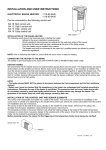
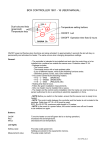
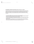
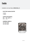
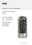
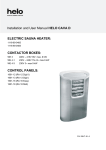
USER MANUAL
RA 18
CONTROL PANEL
Control Panel RA 18 Typ 1601-18
OK
General:
- Control panel is intended to be installed next to the heater in the area outlined in the manual.
- The control panel is compatible with the following heater models:
- 1712 – xx – 0405
( SKSM….DE )
- 1712 – xx – 040520 ( SKSM….DEW )
- 1116 – xx – 0405
( SKLR….DE )
- Maximum heating time 6 hours. Maximum preset time 23 hours.
- Adhere to given installation measurements.
- Heater and connection into the mains can only be carried out by an authorised person according to
current electricity regulations.
- NOTE! Prior to switching the heater on, ensure that the sauna room is ready for heating.
7014382
314 SYRA 23 A
1
Control Panel RA 18 Type 1601-18
Light control on / off
Sauna room temperature display
Time display
Increase setting
OK
OK-button approves changes
Decrease default setting
Heater activation on / off
Control panel:
On/Off button
Starts and stops functions.
When the equipment is active, pressing this button will stop all functions
and display will turn off.
When button is pressed when the equipment is in passive mode (display
off), it will activate the control.
OK button
Approves changes in settings or moves to the next setting depending on
function mode.
+ button
Increase setting
- button
Decrease setting
Light button
Activates a relay on the circuit board. Electrical connectors for lighting
have connectors N and a light-symbol, voltage 230 VAC. A led is
activated next to the button on the Control panel when lights are
activated.
Function times and settings:
- preset time
- function time
- temperature setting
0 ... 23 hours
0 ... 6 hours
0 ... 110 °C
Display during an error:
Err 1
Err 2
Overheating protection activated
Sensor malfunctioning
2
Err 3
Serial traffic is not functioning between the relay card and the Control
Panel
Control panel functions:
Activating the Control panel, the lower display will begin flashing from where the preset time can
be set 0...23 hours by pressing + or - buttons. If OK button is pressed when preset time is zero,
preset will be bypassed and the upper display will start flashing. Here you can set the desired
temperature from 0 to 110 degrees (Celsius) using the + and - buttons. OK button accepts the
temperature, after which the lower display will begin flashing. This setting is for the operation time
from 0 to 6 hours using the + and - button. Once the time is set, press the OK button. Heater
activates.
The temperature sensor monitors the temperature above the heater and controls the temperature to
match that in the M-point. Also functions as a limiting sensor.
Serial traffic card OLEA 83 and Control panel RA 18 connected to OLEA 57 circuit card:
Serial traffic card OLEA 83 connection:
Control panel cable
Serial traffic card’s
connection to the heater’s
Main card.
Red.
White.
Green.
Yellow.
1234
A1
A2
A3
A4
J1
A5
B1
B2
B3
B4
OLEA 83
B5
J2
Control panel is affixed to the wall as described
In the picture.
Check distances from the heater’s installation
Picture
3
min 600 mm
min 300 mm
max 750 mm
max 600 mm
OK
1.
1. Control panel must, without exception, be fitted on the dotted area.
Heater's connection lead's connection box's placement on the wall.
500 mm
A
3.
200 mm
500 mm
A
1.
2.
A=Declared minimum safety distance
1. Suggested placement for the connection box.
2. Siluminium boxes should be used in this area.
3. This area should always be avoided and use siluminium boxes only.
Heat resistant boxes (T125 ºC) and leads should be used in all other areas.
(T170 ºC).
Access to the box must not be obstructed.
When placing the box in areas 2 and 3, local energy board's regulations must be checked.
Check electrical safety regulations section 19 pointing to electrical heater control and safety
equipment.
HEATER'S MINIMUM 1712-...-0405 INSTALLATION MEASUREMENTS (MM)
4
Type
Sauna room
Volume Height
Minimum distance to:
Side
wall
Brackets
1712-30-0405
1712-45-0405
1712-60-0405
1712-80-0405
1712-90-0405
m3
2- 4
3- 6
5- 9
8 - 13
9 - 14
(mm)
mm
1900
1900
1900
1900
1900
mm
30
50
70
100
100
Width of the
niche
Stone
Ceiling Floor
and bench
A
kW
3,0
4,5
6,0
8,0
9,0
Minimum distance
for the wall bracket
D
mm
50
80
100
150
200
F
K
B
J
E
mm
1200
1200
1250
1250
1250
mm
120
120
120
120
120
mm
50
70
90
120
120
mm
390
390
390
390
390
mm
540
580
650
750
-
approx
15
15
23
23
23
(mm)
F
40
D
A
min 30
min 1900
A
K
min 20
min 20
min 30
min 30
D
D
30
MIN.
mm
Max
350
Heater mounting in niche
min 20
m
in
E
Minimum installation measurements
for wall-mounting (mm)
370
B
150
Drill o 3,5 mm
J
Screws 6 x 40 (2 pcs)
Screws 6 x 16 (2 pcs)
HEATER'S MINIMUM 1712-...-040520 INSTALLATION MEASUREMENTS (MM)
5
Type
Sauna room
Minimum distance to:
Volume Height
1712-30-040520
1712-45-040520
1712-60-040520
1712-80-040520
1712-90-040520
kW
3,0
4,5
6,0
8,0
9,0
Side
wall
mm
1900
1900
1900
1900
1900
m3
2- 4
3- 6
5- 9
8 - 13
9 - 14
(mm)
Minimum distance
for the wall bracket
Width of the
niche
Stone
Brackets Ceiling Floor
and bench
A
D
mm
30
50
70
100
100
mm
50
80
100
150
200
F
K
mm
1200
1200
1250
1250
1250
B
mm
120
120
120
120
120
J
mm
50
70
90
120
120
E
mm
390
390
390
390
390
mm
540
580
650
750
-
approx
15
15
20
20
20
(mm)
F
40
D
A
min 30
min 1900
A
K
min 20
min 20
min 30
min 30
D
D
30
MIN.
mm
Max
350
Heater mounting in niche
min 20
m
in
E
Minimum installation measurements
for wall-mounting (mm)
370
B
150
Drill o 3,5 mm
J
Screws 6 x 40 (2 pcs)
Screws 6 x 16 (2 pcs)
6
Connecting heaters 1712-...-0405 and 1712...-040520 into the mains.
Fuse
kW
3,0
4,5
6,0
8,0
9,0
Heater's connection
Cable H07RN-F
mm2
5 x 1,5
5 x 1,5
5 x 1,5
5 x 1,5
5 x 1,5
A
3 x 10
3 x 10
3 x 10
3 x 16
3 x 16
SEPC 62
1000W
1,2,3
3,0
4,5
6,0
8,0
9,0
mm2
5 x 1,5
5 x 1,5
5 x 1,5
5 x 2,5
5 x 2,5
Lämpövastukset, Värmeelement,
Heating elements, Heizeelement
230 V
Teho, Effekt
Input, Leistung
kW
Fixed installation
SEPC 63
1500W
SEPC 64
2000W
SEPC 65 SEPC 65B SEPC 65C
2670W
3000W
3300W
1,2,3
1,2,3
1,2,3
1
1
1
L1
L2
L3
J12
W
J11
V
J10
Control
N
A 12 34 5 B1234 5
U
1234
3
2
1
L
1A
1A
Light
Fun
1 2 3 4
1
N L1 L2 L3 N
N
55
1601-12
A 1 2 3 4 5 B 1 2 3 4 5
1.
2.
3.
2 3 4
5.
4.
1. Syöttö/ Nätet/ Stromnetz/ Power input.
2. Saunavalo-Puhallin/ Bastu belysning/ Saunabeleuchtung/ Sauna light.
3. Sähkölämmityksen vuorottelu/ El.förregling av annan el. förbrukare/
Control of el heating/ Steuerkontact für Verrieglund anderer el.
Verbraucher
4. Ohjauskeskus/ Styrning/ Steuerung/ Control.
5. Tuntoelin/ Sensor/ Fühler/ Sensor.
354 SKSM 133 C
Minimum installation measurements (mm) for 1116-...-0405 heater
7
(x = This measurement is absolute
From corner
40
135
(x
mm
min 900
OLET 19
OLET 19
min 1900
460
3
R 32
A
460
min 10
4 x 0,25
OLET 19
max. 750
990
OK
Heater Minimum installation
distance
kW
A mm
4,5
40
6,5
150
9,0
150
400V
24VDC
Connection lead
Sensor and control unit leads cannot
be so long that they reach into the
400V dotted area
Connecting the heater into the mains
Type
1116-45-0405
1116-65-0405
1116-90-0405
Fuse
kW
4,5
6,5
9,0
A
3 x 10
3 x 10
3 x 16
Heater's connection Fixed installation
Sauna room
lead H07RN-F
Volume Height
mm2
m3
mm
mm2
5 x 1,5
5 x 1,5
3-6
1900
5 x 1,5
5 x 1,5
5 - 10
1900
5 x 1,5
5 x 2,5
9 - 14
1900
8
Teho, Effekt
Input, Leistung
Lämpövastukset, Värmeelement,
Heating elements, Heizeelement
230 V
SEPC 185 SEPC 186 SEPC187
1500W
2170W
3000W
kW
1,2,3
4,5
6,5
9,0
1,2,3
1,2,3
L1
L2
L3
J12
W
J11
V
J10
Control
N
A 12345 B12345
U
1234
3
2
1
L
1A
1A
Light
Fun
1 2 3 4
1
N L1 L2 L3 N
N
55
1601-16
A 1 2 5 B 1 2 3 4 5
1.
2.
3.
2 3 4
5.
4.
1. Syöttö/ Nätet/ Stromnetz/ Power input.
2. Saunavalo-Puhallin/ Bastu-Fläkt/ Saunabeleuchtung-ventilerung/
Sauna light-fan.
1601-16 Ei toimintoa/ Ingen funktion/ No Function/ Keine funktion
3. Sähkölämmityksen vuorottelu/ El.förregling av annan el. förbrukare/
Control of el heating/ Steuerkontact für Verrieglund anderer el.
Verbraucher
4. Ohjauskeskus/ Styrning/ Control/ Steuerung.
5. Tuntoelin/ Sensor/ Fühler/ Sensor.
354 SKLR 14 B
9