1
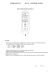
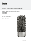
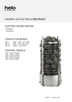
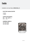
INSTALLATION AND USER INSTRUCTIONS
ELECTRICAL SAUNA HEATER:
1118-60-0405
1118-90-0405
Can be connected to the following control unit:
RA 18
RA 12
RA 13
RA 16
Midi control unit
Digi II control unit
Digi I control unit
Easy control unit
Main switch
INSTALLATION OF THE SAUNA HEATER
The following points have to be observed when installing the heater:
- Adhere to the given installation measurements.
- Wood panelling is recommended as material for the walls and ceiling of the sauna.
- Ensure that the panel wall has been reinforced at the point of the fixing screws.
- Only one heater may be installed into a sauna.
- The heater must only be connected to the mains by a qualified person as defined by current
electricity regulations.
NOTE! Prior to switching the heater on, ensure that the sauna room is ready for heating.
CONNECTING THE HEATER TO THE MAINS
The heater is semi-connected to the mains with H07RN-F (VSN) or A07BB-F(VSB) rubber cable.
HEATER STONES
We recommend that the heater stones are cleaned before placing them onto the heater. The largest stones are placed
at the bottom and the smallest on the top. Stones must not be structured too tightly, or air circulation is inhibited. Nor
must the stones be placed so that heat resistance elements become wedged together or against the heater body. The
stones must completely cover the heat resistance elements. The stones have to be replaced at the latest when they
start to crumble, because otherwise the air circulation through the stones is affected. When replacing the stones, new
stones have to be of a high quality.
NOTE!
- The heater stones MUST NOT be placed in the space between the front soapstones and the first resistance
element.
- Before use it must be checked that the soapstones in the heater are undamaged and installed according to
instructions. Otherwise the use of the heater is prohibited. The guarantee does not cover faults due to poor
air circulation caused by small and tightly packed stones. Ceramic stones may damage the heater. The
guarantee of the heater does not cover any damage caused by their use.
INSTALLATION OF THE CONTROL UNIT AND SENSOR ELEMENTS
The control unit is electrically connected via a cable to the heater. The control unit is intended for installation in the
sauna room or outside of it, depending on the model of the control unit. Check the control unit location from the control
unit installation and user instructions.
The sensor is fixed to the wall of the sauna, directly on the middle line of the heater, 40mm from the ceiling. Any
deviation from the given installation measurements will cause a risk of burns.
The temperature limiter in the sensor element cuts off all the heating energy to the heater if the heater temperature
increases to a level where it causes a danger to the wooden parts of the sauna. Once the temperature is reduced the
limiter can be restored by pressing the restore button.
Before pressing restore, the reason for the triggering of the temperature limiter must always be clarified!
Sensor OLET 19
Restore
7013482 314 SKLT 3 B
Once the adjustable legs are turned in the
fixing height of the heater, wall rack is 750mm
from the floor. The adjustable legs have a 15mm
adjustment allowance just in case the floor is on
an incline.
Check after fixing to the wall that both adjustable
legs are evenly set against the floor.
The measurement between the fixing holes of the
rack to be fixed on the wall is 240mm.
Wall fixing parts:
- locking pieces for the heater (A)
- wall fastener (B)
- metal screw 4.2 x 13mm
- cover screw 6 x 40mm
Drill diameter o 3,5 mm
Min.
240 240 mm
Min 750 mm Max 765 mm
FIXING THE HEATER TO THE WALL.
240 mm
A
2 pieces
1 piece
2 pieces
2 pieces
B
Fit the locking pieces (A) for the heater into the
holes in the back plate so that the entering part
turns upwards.
Fix the wall rack (B) to face the wall so that the
holes where the locking pieces are fixed will be
upwards. The rack can also be fixed directly to
the heater. Mark in advance the locations of the
screws to the wall and, if needed, drill small
guide holes and then fix the heater to the wall
with the screws supplied.
The illustration shows how the wall rack should
be fixed in the heater.
The parts in the heater are fixed to the wall rack
with metal screws.
2
Heater's connection lead's connection box placement on the wall.
100 mm
3.
1.
2.
500 mm
200 mm
500 mm
100 mm
1. Suggested placement for the connection box.
2. Siluminium boxes should be used in this area.
3. This area should be avoided and the siluminium box used
A heat resistant box (T125 ºC) and leads (T170°C) should be used in all other areas.
The connection box should be in a place where it is easy to service. When placing the
connection box in areas 2 and 3, the local energy board's instructions and regulations
must be checked.
Check electrical safety regulations section 19 concerning electrical heater control and
safety equipment.
Soapstone user manual
As soapstones are used in the heater, it is extremely important that the sauna is correctly heated
the first few times. This ensures that the soapstones will not crack even at high
temperatures.
1. The first heating *): Set the heater to approx. a 50°C setting for about an hour. Then disconnect
the heater and let the stones cool down.
2. The second heating *): Set the heater to approx. a 80°C setting for about an hour. Then
disconnect the heater and let the stones cool down.
3. No water should be thrown on the heater during the first heating time to enable the soapstones
gradually to become hardened.
4. After the second heating the heater can be used normally.
5. It is typical of soapstones that they may become coloured during use. The reason for the
colouring can be the high temperature of the stones or the quality of the water thrown on the
heated stones.
*) If the Easy control centre is used, set the heater to the lowest setting for about an hour during
the first time. During the second heating the temperature has to be set a couple of notches higher
than during the first heating. The second heating should also last for about an hour. Then the
heater can be used normally.
3
SAUNA VENTILATION
Recommendation for a sauna with a mechanical ventilation system
5
C
C
A
C
C
AA
7
4
1
6
2
1000 mm
5
1000 mm
min
500 mm
1
1
4
B
B
3
3
1. Sauna room
3. Electrical heater
5. Discharge flue or duct
2. Washing room
4. Exhaust valve
6. Sauna room door
7. This can also be fitted with a ventilation valve which is shut when the sauna is heated and in use.
When a mechanical ventilation system is used, the entry of fresh air is located to area A.
When ventilation is implemented via natural air circulation (for example through the wall), the entry valve
is placed in area B and the exit valve at least 1m higher and as far as possible from the heater.
Due to the sensor element OLET 19 location, placing of the entry valve in area C should be
avoided !
Heater installation measurements
OLET 19
*) 40
(mm)
(mm)
1070
*) = definite measure
100
490
100
280
D
1900
830
max
450
10
10
max
450
All the measures are minimum distances unless otherwise stated !
Connecting the heater to the mains
Power
kW
6,0
9,0
Saunaroom
Min. Installation distance Heater's connection Fixed installation
Capacity Height from the stone surface
lead
(D - measure)
H07RN-F
m3
mm
mm
mm2
mm2
min max min
5 - 10
1900
300
5 x 1,5
5 x 1,5
9 - 13
1900
350
5 x 1,5
5 x 2,5
Fuse
A
3 x 10
3 x 16
4
Wiring diagrams
Teho, Effekt
Input, Leistung
Lämpövastukset, Värmeelement,
Heating elements, Heizeelement
230 V
kW
SEPC 64
2000W
6,0
1,2,3
SEPC 65 SEPC 65B SEPC 65C
2670W
3000W
3300W
9,0
1,2,3
L1
L2 L3
J12
W
J11
V
J10
Control
N
A 12 3 4 5 B 1 2 3 4 5
U
1234
3
2
1
L
1A
1A
1 2 3 4
Light
Fan
1
5.*
)
1 2 3 4 5 6
N
N
N
2.*
)
6.
55
L1 L2 L3
1.
2 3 4
3.*
)
4.
*) Katso ohjauskeskuksen käyttöohje
Se styrpanelens bruksanvisning
Sehe die Bedienungsanleitung des
Steuergerätes
See the control panel manual
1. Syöttö / Nätet / Stromnetz / Power input.
2. Saunavalo / Bastu belysning / Saunabeleuchtung / Sauna light. max 100W
3. Tuuletin / Fläkt / Ventilator / Fan max 100W
4. Sähkölämmityksen vuorottelu/ El.förregling av annan el. förbrukare/
Signal kontakt / Signal contact
5. Ohjauskeskus / Styrpanel / Steuergerät / Control panel.
6. Tuntoelin / Sensor / Fühler / Sensor.
354 SKLT 1 A
Connector strip
Heater
4
3
2
1
Sensor element cable
1. Blue.
2. White.
3. Red.
4. Yellow
Limiter
4
3
2
1
1. Blue.
2. White.
3. Red.
4. Yellow
5
Principal wiring diagram
Sensor
Heater
N
L1 L2 L3
N
Sauna light
230V 100W
Input 400V 3N~
(NOTE !
No function
with the
RA 16 Easy
control centre!)
N
55
Electrical heating
Control 230V
Fan
230V 100W
(NOTE !
Not with the RA 18
Midi control centre
or RA 16 Easy
control centre !)
Control unit
RA 16 (Easy)
RA 18 (Midi)
Digi I (2001)
Digi II (2002)
6
HELO CAVA – ASSEMBLY INSTRUCTIONS FOR THE HEATER SOAPSTONES
Before the installation of the soapstones the heater has
to be fixed to the wall. See the instructions on page 2.
Take the front soapstones out from the package.
The stone to be placed as the lowest has rounded lower
corners. Pass the stones carefully along the loop. The
other (4 pcs) soapstones have even edges and
therefore it does not matter in which order they are
placed.
Install the intermediate pieces (8) of the soapstones so
that the projection will always stay on the stone i.e. there
will always be an air gap between the stones.
The metal pieces are placed on each side between each
stone (except the uppermost).
Once the front soapstones have been installed, place
the stones meant to be inside the heater (approx. 30kg).
Some stones also have to be placed on the resistance
elements.
NOTE! No heater stones should be placed between
the first resistance element and the front
soapstones. The heater should not be used without the
front soapstones or when the stones have cracks on
them.
7
After installing the inside stones, install the support
rods above them.
The illustration shows the order.
The heater body has both vertical and end limiters
which prevent the movement of the soapstone both
vertically and horizontally once they are installed.
Install the support rods between the vertical limiters.
The soapstones also remain between the vertical
limiters.
End limiter
The illustration shows the installed support rods.
The soapstones are installed as follows:
- Install the upper stone first.
- Place as shown in the illustration: first one of the
ends under the edge; push the stone then under the
other edge until it stops in the end limiter.
NOTE!
The stone has to remain behind the vertical limiter.
8
Install the round-edged stone next. Push the other end
under the edge and then push the stone along the
support plate against the end limiter.
In the illustration the round edge stone and the
soapstone furthest at the back remain where they are.
The illustration shows both the vertical and horizontal
limiters of the soapstones.
Install the middle stones. The length of the middle
stones is 405mm. Push the stone first under the right
edge and then along the support plate under the left
edge against the end plate.
Finally check that the soapstones are between the end
limiters and that the gaps between the stones are
equal.
9