1
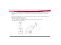
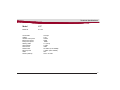
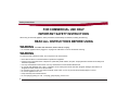
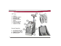
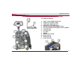
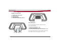
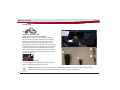
User Manual
X17 ECO Carpet Extractor
This manual is furnished with each new Minuteman X17. This provides the necessary operating and preventive
maintenance instructions. Operators must read and understand this manual before operating or servicing this
machine.
This machine was designed to give you excellent performance and efficiency. For best results and minimal cost,
please follow the general guidelines below:
· Operate the machine with reasonable care.
· Follow the manufacturer’s suggested maintenance instructions as provided in this booklet.
· Use original Minuteman supplied parts.
2
Technical Specifications
Model
X17
Model No.
X17115
Current Max.
Voltage
Vacuum motor power
Brush motor power
Pump motor power
Working width
Gross Weight
Sound Level
Solution tank
Recovery tank
Cable
Suction (sealed)
12 Amps
115V
1250W
100W
50PSI
17” (43cm)
110 lbs.
72dB
10 Gallon (37.8 LITERS)
7 Gallon (26.5 LITERS)
50 ft.
100 in. of water
3
CE Declaration
4
Table Of Contents
Table of Contents
Technical Specifications .................................................................................................................................................... 3
CE Declaration .................................................................................................................................................................... 4
Table Of Contents ............................................................................................................................................................... 5
Safety Instructions ............................................................................................................................................................. 6
For Safety During Operation ................................................................................................................................................ 7
Unpacking Instructions ......................................................................................................................................................... 8
Assemby ........................................................................................................................................................................... 10
Machine Overview ............................................................................................................................................................ 12
Front ................................................................................................................................................................................... 12
Back ................................................................................................................................................................................... 13
Handle\Control Panel ......................................................................................................................................................... 14
Circuit Breakers .................................................................................................................................................................. 14
Solution Tank In-line Filter .................................................................................................................................................. 16
Solution Tank Drain Hose ................................................................................................................................................... 17
Solution Level Indicator ...................................................................................................................................................... 17
Brush Pressure Gauge ....................................................................................................................................................... 18
Handle Adjustment ............................................................................................................................................................. 19
Accesories .......................................................................................................................................................................... 20
Operating Instructions ..................................................................................................................................................... 21
Maintenance ..................................................................................................................................................................... 22
Troubleshooting ............................................................................................................................................................... 24
Minuteman International Made Simple Commercial Limited Warranty........................................................................ 26
5
Safety Instructions
FOR COMMERCIAL USE ONLY
IMPORTANT SAFETY INSTRUCTIONS
When using an electrical appliance, basic precautions should always be followed, including the following:
READ ALL INSTRUCTIONS BEFORE USING
WARNING - To reduce the risk of fire, electric shock, or injury:
• Do not leave appliance when plugged in. Unplug from outlet when not in use and before servicing.
WARNING
To reduce the risk of electrical shock, do not expose to rain. Store indoors.
• Never allow children or untrained adults to operate this equipment.
• Keep the area of operation clear of all persons, particularly small children, and pets. Keep bystanders at least 25 feet away from
the area of operation.
• Use only as described in this manual. Use only manufacturer’s recommended attachments.
• Do not use with damaged cord or plug. If appliance is not working as it should, has been dropped, damaged, left outdoors, or
dropped into water, return it to a service center.
• Do not pull or carry by cord, use cord as a handle, close a door on cord, or pull cord around sharp edges or corners.
• Do not run appliance over cord.
• Keep cord away from heated surfaces.
• Do not unplug by pulling on cord. To unplug, grasp the plug, not the cord.
6
Safety Instructions
• Do not handle plug or appliance with wet hands.
• Do not put any object into openings. Do not use with any opening blocked; keep free of dust, lint, hair, and anything that may reduce
air flow.
• Keep hair, loose clothing, fingers, and all parts of body away from openings and moving parts.
• Do not pick up anything that is burning or smoking, such as cigarettes, matches, or hot ashes.
• Turn off all controls before unplugging.
• Use extra care when cleaning on stairs.
• Do not use to pick up flammable or combustible liquids such as gasoline or use in areas where they may be present.
• Connect to a properly grounded outlet only. See grounding instructions.
• If foam/liquid comes out of exhaust openings turn switch off immediately.
• Use only chemicals recommended by dealer/manufacturer.
SAVE THESE INSTRUCTIONS
7
Unpacking Instructions
INSPECTION
Carefully unpack and inspect your machine for shipping damage. Each unit is tested and thoroughly inspected before shipment, and any
damage is the responsibility of the delivery carrier who should be notified immediately.
ELECTRICAL
This machine is designed to operate on a standard 112 amp. 115 volt, 60 hz, AC circuit. Voltages below 105 volts AC or above 125 volts
AC could cause serious damage to the motor.
WARNING
Electric motors can cause explosions when operated near explosive materials or vapors. Do not operate this machine near flammable
materials such as solvents, thinners, fuels, grain dust, etc.
GROUNDING INSTRUCTIONS
This appliance must be grounded. If it should malfunction or breakdown, grounding provides a path of least resistance for electric current
to reduce the risk of electric shock. This appliance is equipped with a cord having an equipment-grounding conductor and grounding plug.
The plug must be plugged into an appropriate outlet that is properly installed and grounded in accordance with all local codes and
ordinances.
DANGER
Improper connection of the equipment-grounding conductor can result in a risk of electric shock. Check with a qualified electrician or
service person if you are in doubt as to whether the outlet is properly grounded. Do not modify the plug provided with the appliance — if it
will not fit the outlet, have a proper outlet installed by a qualified electrician.
This appliance is for use on a nominal 115-volt circuit and has a grounding plug that looks like the plug illustrated in sketch A below. Make
sure that the appliance is connected to an outlet having the same configuration as the plug. No adapter should be used with this
appliance.
8
9
Assembly
HANDLE ASSEMBLY
The X17 Handle Assembly (D) is not assembled on the
machine when shipped. Follow the instruction on page 13
to connect the handle assembly to the machine.
A
B
C
D
E
10
HANDLE ADJUSTMENT KNOB
SHOULDER BOLT
COVER
HANDLE ASSEMBLY
SCREW
Assembly
Unpack machine.
Use philips screwdriver to
unscrew 4 screws and
remove cover.
Insert handle assembly in
between bushings. Insert the
shoulder bolt through the
bushing and screw into the
handle assembly using
supplied wrench.
Align the teeth on the bushing
and handle assembly before
tightening the adjustment
knob.
Spin the adjustment knob
clockwise to tighten.
Attach the wire harness
to the machine.
The wire harness must
be aligned with the patterns
on the connector to fit.
Screw the cover back
with the 4 screws.
11
Machine Overview
X17 Front
A HANDLE
B RECOVERY DOME LID
C RECOVERY TANK
D SOLUTION TANK
E SOLUTION TANK LID
F WHEEL
G RECOVERY WINDOW
H CHASIS ASSEMBLY
J FAUCET FILL HOSE
Vacuum Connection
K
L
M
N
12
VACUUM MOTOR INTAKE
VACUUM INTAKE CONDUIT
UMBRELLA CONNECTION
RECOVERY INLET
Machine Overview
X17 BACK & Bottom
A.
B.
C.
D.
E.
F.
G.
H.
J.
K.
L.
M.
N.
P.
TWIST LOCK POWER CONNECTOR
HANDLE ADJUSTMENT KNOB
AUXILLIARY POWER OUTLET
RECOVERY TANK DUMP HOSE
BRUSH PRESSURE ADJUSTMENT KNOB
OFF AISLE WAND WATER FEMALE QUICK-CONNECT
VACUUM HOSE
IN-LINE FILTER
VAC SHOE
BRUSH
BRUSH SHOE COVER
SPRAY JETS (2)
BRUSH MOTOR
FLOAT SHUT-OFF
13
Machine Overview
Handle/ Control Panel
A
B
C
D
MOMENTARY SPRAY BAIL
BRUSH SWITCH
VACUUM SWITCH
SPRAY JET \AUXILLIARY SWITCH
Circuit Breakers
The circuit breakers are located on bottom and rear
of the handle assembly.
1 BRUSH MOTOR BREAKER - 3amp
2 VACUUM PUMP BREAKER - 12amp
3 SPRAY JET PUMP\AUX POWER & PUMP BREAKER - 4amp
If any of the functions above are not operating, check if the
circuit breaker buttons have tripped. Press to reset.
14
Machine Overview
Momentary Handle
(A) When handle is pushed forward the spray jets shutoff.
Brush Switch
(B) ON\OFF switch for brush. Flip switch up to (I) position to power on the brush motor. Flip switch
to (o) position to shut off brush motors. Note: Brush switch must be turned ON for to use spray jets.
Vacuum Switch
(C) ON\OFF switch for vacuum pump. Flip switch up to (I) position to turn on vacuum pump. Flip
switch to (o) position to shut off pump.
Spray Jet/ Auxilliary Switch
(D) Power switch for spray jet and auxilliary switch. Push the switch to the (I) position to power
ON the spray jets. Note: The spray jets will not work unless the brush is powered ON.
Push switch to (II) position to use the Off-aisle wand. This will power the auxilliary
outlet and will turn the pump on for the auxilliary connection. See page 20 for connection details.
15
Machine Overview
Solution Tank In-line Filter
The In-line Filter (B) should be cleaned regularly. To remove, turn the Shut-off
Valve (C) closed by turning it clockwise. Next, twist the Filter Cap (A) counter-clockwise and
pull the filter out to clean.
16
Machine Overview
Solution Tank Drain Hose
The solution tank may be drained by removing the
Solution Tank Drain Hose (A) from the Hose Barb (B)
and routing the hose to a floor drain.
Solution Level Indicator
The solution Tank Drain Hose also serves
as a water level indicator for the solution
tank. The amount of water remaining in the
solution tank can be seen through the clear
drain hose.
17
Machine Overview
Brush Pressure Gauge
The brush pressure gauge informs the operator if the brush
pressure setting is in optimum range. The machine
operates best in the green area. If the machine reaches the
yellow or red range the brush pressure can be lowered by
raising the brush by turning the brush pressure adjustment
knob counter-clockwise.
18
Machine Overview
Handle Adjustment
The X17 handle was designed with operator comfort in
mind. The angle position of the handle can be adjusted
to suit the needs of the operator.
Angle Adjustment
The handle can be adjusted without tools by loosening the
Handle Adjustment Knob (A) and rotating the handle
to the desired position.
Cord Relief
Use cord relief to prevent cables from
disconnecting. Lock the cord in place by
looping the cable and threading the cable
through the relief, then pull the cable down
so it locks into place as shown in figure 2.
Figure1
Figure 2
19
Machine Overview
Accessories
C46300-00 - Motorized Tool
Only this tool may plug into the Auxiliary
Power (B). The vacuum hose as shown on Page 13
Item (G) must be first disconnected from the machine
before the motorized tool can be connected. Connect
the tools Suction Hose (D) to the machines Vacuum
Inlet (A) Then connect the motorized tool Power Cord (E)
to the Auxiliary Power (B). A Coupler-quick Connect (G) is
required to connect the tool’s Solution Hose (F) to the
quick-connect Solution Coupling (C). To turn ON the tool
the auxilliary switch must be in the (II) position as shown
on Page 14 Item (D).
TM1001 - Upholstery Tool
The same applies to the upholstery tool except this tool
does not require auxiliary power to be used.
Caution! Brush motor must be turned OFF when using auxiliary function. If the brush motor is ON, water will
continue to spray from the spray jets, causing reduction in water pressure to auxillary tool.
20
water will
Operating Instructions
OPERATING INSTRUCTIONS
FILLING THE X17
Remove clear solution cover lid from front of machine, page 12 item D,or use the supplied faucet fill hose, item J. Fill solution tank with desired amount of
warm water and add liquid cleaning chemical, Minuteman Extraction Shampoo order #902163. (See instructions on container for proper dilutions.) DO NOT
USE powdered cleaning chemicals. Powders are unlikely to dissolve thoroughly, resulting in clogging the inline solution strainer. This can reduce or stop
solution flow to the pump and spray jets.
Carpet should be thoroughly vacuumed and obstacles relocated before beginning the cleaning cycle. Heavy traffic lane areas should be pre-treated or
spotted with Minuteman Pre-Treat order #902183 for best results.
TO BEGIN CLEANING:
1. Always work away from the cord.
2. Machine operates by pulling backwards over carpet.
3. The recovery dome lid, page 12, item B, should be properly seated on Recovery Tank, item C, for proper vacuum recovery.
4. See page 14, Control Panel Switch Identifications:
Normal Cleaning Mode
1. Turn on vacuum switch (C).
2. Turn on brush switch (B).
3. Turn on the solution pump (D). Note: Solution pump will not turn on if the brush is not powered on.
4. Adjust brush pressure at rear of machine, until brush pressure gauge reads in green zone.
5. Solution pump should be turned off by either using the momentary bail, item A,or flip the switch to the center position, page 14, item D, 6" before the
end of each cleaning pass.
During the cleaning cycle, care should be taken not to allow foam to build up in the recovery tank. If this should happen, the machine should be turned off.
Defoamer order #910543 should be added to the recovery tank only, never into the solution tank. Foam should not be allowed to enter vacuum filter screen.
The recovery water level can be viewed from the operator’s position of the machine through the visible recovery dome. The X17 has a float ball shut off
located in the recovery tank that cuts off suction to the vacuum hose. The machine will get louder when the recovery tank is full. (NOTE : Never tilt machine
completely back with recovery tank in place. Always remove tank and set to the side before tilting complete machine.) To empty the recovery tank use the
recovery tank dump hose, page 13, item D. Unclip the hose from the tank and turn the cap a quarter turn counter-clockwise and dump waste water into a floor
drain or slop sink.
21
Maintenance
USER MAINTENANCE INSTRUCTIONS
All service and repair should be performed by qualified vacuum service representative or electrician. No user serviceable components are
employed in the electrical vacuum lid head assembly. No lubrication of the motor is required. Before cleaning or maintaining the machine
unplug the electrical supply plug.
DAILY MAINTENANCE
1.
2.
3.
4.
5.
6.
7.
Solution tank should be emptied after each use. Flush pumping system with 2 or 3 gallons of clean hot water.
Vacuum shoe should be cleaned of any debris daily.
Removable recovery tank, page 12, item C, should be rinsed clean daily (leave clean cover removed when storing).
Spray jets should be checked for correct spray pattern and cleaned if plugged. Spray jets are quick release 1/4 turn type. By twisting item
1/4 turn counter clockwise, jets can be removed for cleaning. Do not clean out spray tips with pins or wire, this may cause damage to the
jet spray pattern and cause streaking.
Protect equipment from freezing. Severe pumping system damage can occur if allowed to freeze.
Inspect vacuum hoses for tight connections. Check electrical cable for abrasion or cuts in jacket. Cord should be replaced if worn or
damaged.
Remove carpet string from brush daily.
MONTHLY/BI-MONTHLY MAINTENANCE
The X17 Solution Pump System should be purged twice monthly to remove alkaline residue build-up. The system should be flushed twice,
once with the jets installed and once with jets removed. To flush system out, use 1 quart of white vinegar to two gallons of clean hot water,
followed by a clear 2 gallon rinse. Clean spray jets if required. The recovery window must be removed and cleaned monthly. To remove the
recovery window unscrew the 2 screws. When replacing the recovery window make sure there is a water tight seal between the gasket and
the tank.The recovery tank air filter located on top of the recovery tank under the lid needs to be cleaned monthly. To clean filter remove the
recovery dome lid then unscrew the 3 thumb screws located on the float shut off remove filter and rinse clean. There is also a screen located
inside the float shut off that needs to be removed and cleaned weekly.
22
Maintenance
CORD STORAGE
The X17 is supplied with a detachable cord for ease of storage.
• Regularly inspect cord for signs of damage. If cord is damaged replace immediately.
• Do not use with damaged cord or plug. If appliance is not working as it should, has been dropped, damaged, left outdoors, or dropped into
water, return to service center.
• Do not pull or carry by cord, use cord as handle, close a door on cord, or pull cord around sharp edges or corners. Do not run appliance
over cord. Keep cord away from heated surfaces.
• Do not unplug by pulling cord. To unplug, grasp the plug, not the cord.
• Do not handle plug or appliance with wet hands.
• This equipment should be stored indoors and not exposed to rain.
23
Troubleshooting
24
Troubleshooting
25
Minuteman International Made Simple Commercial Limited Warranty
REVISION E
EFFECTIVE 1/1/2009
Minuteman International, Inc. warrants to the original purchaser/user that the product is free from defects in workmanship and materials
under normal use. Minuteman will, at its option, repair or replace without charge, parts that fail under normal use and service when operated
and maintained in accordance with the applicable operation and instruction manuals. All warranty claims must be submitted through and
approved by factory authorized repair stations.
This warranty does not apply to normal wear, or to items whose life is dependent on their use and care, such as belts, cords, switches, hoses,
rubber parts, electrical motor components or adjustments. Parts manufactured by Minuteman are covered by and subject to the warranties
and/or guarantees of their manufacturers. Please contact Minuteman for procedures in warranty claims against these manufacturers.
Special warning to purchaser — Use of replacement filters and/or prefilters not manufactured by Minuteman or its designated licensees,
will void all warranties expressed or implied. A potential health hazard exists without original equipment replacement.
All warranted items become the sole property of Minuteman or its original manufacturer, whichever the case may be.
Minuteman disclaims any implied warranty, including the warranty of merchantability and the warranty of fitness for a particular purpose.
Minuteman assumes no responsibility for any special, incidental or consequential damages.
This limited warranty is applicable only in the U.S.A. and Canada, and is extended only to the original user/purchaser of this product.
Customers outside the U.S.A. and Canada should contact their local distributor for export warranty policies. Minuteman is not responsible for
costs or repairs performed by persons other than those specifically authorized by Minuteman. This warranty does not apply to damage from
transportation, alterations by unauthorized persons, misuse or abuse of the equipment, use of non-compatible chemicals, or damage to
property, or loss of income due to malfunctions of the product.
26
If a difficulty develops with this machine, you should contact the dealer from whom it was purchased.
This warranty gives you specific legal rights, and you may have other rights which vary from state to state. Some states do not allow the
exclusion or limitation of special, incidental or consequential damages, or limitations on how long an implied warranty lasts, so the above
exclusions and limitations may not apply to you.
Cord Electric Group………. Three years parts, two years labor, ninety days travel (Not to exceed two hours)
Exceptions……….
Port-A-Scrub, one year parts, six months labor
MPV 13, one year parts
V Series Upright Vacuums, One year parts, one year labor
MPV 14 and 18, two years parts, one year labor
RapidAir blower, one year parts, one year labor
Explosion-Proof Vacuum, one year parts, one year labor
X12 and X12H, one year parts, one year labor
TRS 14, one year parts, one year labor
E17/E20 electric scrubbers, one year parts, six months labor
Battery Operated Group….. Three years parts, two years labor, ninety days travel
(Not to exceed two hours)
Exceptions……Sweepers, one year parts, one year labor, ninety days travel
(Not to exceed two hours)
Internal Combustion Group….One year parts, one year labor, ninety day travel
(Not to exceed two hours)
Exceptions………..Mirage propane burnisher, one year parts, one year labor
27
Excellence Meets Clean
Minutman International · 14N845 U.S. Route 20 · Pingree Grove, Illinois 60140 USA
Phone 800- 237-3192
E-Mail, www.minutemanintl.com
A Member of the Hako Group
988725UM
Rev * 01/09