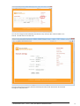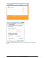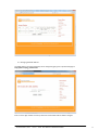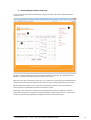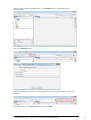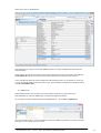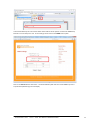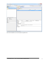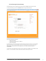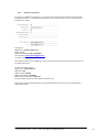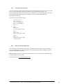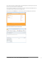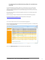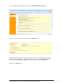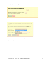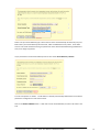
1
Quick Installation Guide For Environmental Sensors Printed October 5, 2014 - Rev 21 – PART DOC-MANUAL-SENSORGATEWAY 1 Copyright: Copyright © 2014 ServersCheck BVBA All rights reserved. Reproduction without permission is prohibited. Software: The software described in this manual is furnished under a license agreement and may be used only in accordance with the terms of that agreement. Trademarks: ServersCheck is a trademark of ServersCheck. All other trademarks or registered marks in this manual belong to their respective manufacturers. Disclaimer: Information in this document is subject to change without notice and does not represent a commitment on the part of ServersCheck. ServersCheck provides this document “as is,” without warranty of any kind, either expressed or implied, including, but not limited to, its particular purpose. ServersCheck reserves the right to make improvements and/or changes to this manual, or to the products and/or the programs described in this manual, at any time. ServersCheck has made this document to the best of its abilities. However ServersCheck assumes no responsibility for its use, or for any infringements on the rights of third parties that may result from its use. This product might include unintentional technical or typographical errors. Changes are periodically made to the information herein to correct such errors, and these changes are incorporated into new editions of the publication. For safety reasons, the SensorGateways and sensor probes may never be moved, fully or partially covered while operating. Warranty: For the warranty on this product please visit http://www.serverscheck.com/ OPENING SENSORGATEWAY OR EXTERNAL SENSOR PROBE VOIDS THE WARRANTY Certifications: The ServersCheck sensors are FCC (Class A) & CE (Class B) certified. Certificates can be downloaded from http://www.serverscheck.com/sensors ServersCheck sensors were tested and certified by following international certification bodies: Printed October 5, 2014 - Rev 21 – PART DOC-MANUAL-SENSORGATEWAY 2 Table of Contents 1. ServersCheck Sensors Overview ............................................................................ 5 1.1 Unboxing video of the ServersCheck sensors ................................................. 5 1.2 SensorGateway Quick Overview ..................................................................... 5 1.3 External Sensor Probes ................................................................................... 6 2. Connecting the ServersCheck Sensor Probes ......................................................... 7 2.1. General Instructions ....................................................................................... 7 2.2. View of connected Temperature Sensor ........................................................ 8 2.3. View of connected Temperature&Humidity Sensor ....................................... 8 2.4. View of connected Flooding Sensor ............................................................... 9 2.5. View of connected a Power Failure Sensor .................................................... 9 3. Using the Wireless Sensors ................................................................................. 13 3.1. Connect wireless hub to SensorGateway .................................................... 10 3.2. Connect wireless sensors to SensorGateway .............................................. 10 3.3. Disconnecting the wireless sensors ............................................................. 12 3.4. Restrictions .................................................................................................. 12 3.5. Reconnection Window ................................................................................ 12 4. Configuring the SensorGateway to the Network ................................................ 13 4.1. Set your PC in the same network segment as the SensorGateway ................. 13 4.2. Connecting to the SensorGateway .................................................................. 14 4.3. Changing the MAC Address ............................................................................. 17 5. SensorGateway Interface Overview ................................................................... 18 6. Configuring the SensorGateway’s access security .............................................. 19 7. Configuring the Farenheit / Celsius readings ...................................................... 20 8. Configuring internal clock of the SensorGateway ............................................... 20 9. Configuring the SensorGateway for SNMP ....................................................... 221 9.1. SNMP Get Requests ................................................................................... 221 9.2. SNMP Traps ................................................................................................. 24 10. Email alerting from SensorGateway ................................................................... 27 10.1. Gmail as E-‐mail Server ................................................................................. 21 10.2. Tunneling an SSL Connection ....................................................................... 29 10.3. Mail Service Like AuthSMTP.com ................................................................ 29 11. SMS alerting from SensorGateway .................................................................. 31 12. Setting threshold values in the SensorGateway for alerting ........................... 33 13. Logging ............................................................................................................ 35 13.1. Alert Log ....................................................................................................... 34 13.2. XML Output ................................................................................................. 34 14. Sensor Calibration ........................................................................................... 35 15. Factory resetting of SensorGateway ............................................................... 36 15.1. SensorGateways v1 and v2 .......................................................................... 36 15.2. SensorGateways v3 and v4 .......................................................................... 37 15.3. SensorGateway v5 ....................................................................................... 38 16. Updating the firmware of the SensorGateway ............................................... 39 17. SensorGateway’s LED table ............................................................................. 41 17.1. Normal Power on Reset, No New Firmware Uploaded ............................... 41 17.2. Reboot, New Firmware Uploaded ............................................................... 41 18. OLED Display Subscripts .................................................................................. 42 19. Rack mounting the SensorGateway ................................................................ 42 20. The IO Sensor Probe – 16 Dry Contacts IN & 4 OUT ........................................ 43 Printed October 5, 2014 - Rev 21 – PART DOC-MANUAL-SENSORGATEWAY 3 20.1. General Description ................................................................................. 43 20.2. Specifications ........................................................................................... 43 20.3. Applications ............................................................................................. 43 20.4. Terminal Description ................................................................................ 43 20.5. Mounting instructions .............................................................................. 44 20.6. Basic Wiring Diagram ............................................................................... 44 20.7. SensorGateway IO Sensor Probe Interface .............................................. 47 20.8. Wiring configuration and settings (anti tampering) ................................. 48 20.9. Output Triggering – Automatic and SNMP Set ......................................... 52 21. Security Sensors .............................................................................................. 54 21.1. General Description ................................................................................. 54 21.2. View of Door Sensor ................................................................................ 54 21.3. View of Motion Sensor ............................................................................. 55 21.4. View of Smoke Sensor .............................................................................. 55 22. Sound Sensor ........................................................................................................ 56 22. 1. View of Sound Sensor ............................................................................... 56 23. Stainless Steel Temperature Sensor Assembly ..................................................... 60 24. The Sensor Hub .................................................................................................... 60 24.1. General Description ...................................................................................... 60 24.2. Specifications ................................................................................................ 60 24.3. Probe Restrictions ........................................................................................ 60 24.4. Connecting the SensorHub to the SensorGateway ....................................... 61 24.5. Terminal Connections ................................................................................... 61 24.6. Basic wiring ................................................................................................... 62 24.7. The SensorGateway Webpage ..................................................................... 63 24.8. Output Triggering – Automatic and SNMP Set ............................................. 64 25. Control Functions ................................................................................................. 66 25.1. Configuration ................................................................................................ 66 25.2. Wiring ........................................................................................................... 66 26. Cloud Platform ..................................................................................................... 67 26.1. Registration .................................................................................................. 67 26.2. SensorGateway Identification ...................................................................... 68 26.3. Sensor Dashboard ........................................................................................ 68 26.4. Alerts ............................................................................................................ 69 26.4.1. Threshold Alerts ........................................................................................ 69 26.4.2. If-‐Then (IFT) Alerts ..................................................................................... 70 26.5. SensorGateway Location .............................................................................. 72 27. Configuring the ServersCheck Monitoring Software for centralized sensor monitoring ...... 73 28. Configuring heat maps in the ServersCheck Monitoring Software / Appliance ............. 79 28.1. Creating a floor map of the server room or data center .......................... 79 28.2. Preparing the heat maps in the ServersCheck Monitoring Software / Appliance ... 80 28.3. Mapping sensors on your floor plan ........................................................ 81 29. Power Rating ................................................................................................... 83 For technical support kindly visit http://www.serverscheck.com/support Printed October 5, 2014 - Rev 21 – PART DOC-MANUAL-SENSORGATEWAY 4 1. ServersCheck Sensors Overview 1.1 Unboxing video of the ServersCheck sensors We invite you to watch following unboxing video before unpacking, installing and configuring your ServersCheck sensors: http://www.serverscheck.com/sensors/sensorgateway_unboxing_video.asp 1.2 SensorGateway Quick Overview The SensorGateway is the heart of the ServersCheck environmental sensors. This base unit is where all the smart logic resides: from connection to monitoring, reporting and alerting. The SensorGateway is connected to the network via a standard network cable over a 10/100Mbps network. It supports PoE too. This allows for powering the sensors without having to rely on external power adapters. If you don’t have a PoE network then a power adapter is optionally available. In the following sections of this user manual, we are going to describe in detail the configuration and operation of the base unit. It is recommended to verify the calibration of the temperature probe in your environment and if an offset is noticed, to recalibrate the sensor as explained in section 11 of this document. The maximum tested length between a PoE switch and the SensorGateway is 100ft or 30 meters. Actuals may vary depending on cable quality, switch and environmental factors. Printed October 5, 2014 - Rev 21 – PART DOC-MANUAL-SENSORGATEWAY 5 1.3 External Sensor Probes ServersCheck uses external sensor probes for its environmental monitoring solution. The flooding/water and power failure sensors from ServersCheck have 2 openings: - RJ45 connector - Plug for power adapter Only the power sensor requires a power adapter plugged into it; the power adapter’s current sent to the sensor will be used to analyze the power state. The flooding sensor doesn’t require any power adapter and is powered through the SensorGateway. IMPORTANT NOTICE FOR WATER / FLOODING SENSORS The flooding / water detection sensor consists of 2 parts: the sensor (gray box with ServersCheck label on it) and the purple water sensing cable (shown left). Only the purple cable may be submerged – this is the water sensitive part of the sensors! The sensor probe (gray box) has to be kept at all times above the water level. You can replace the shipped RJ45 cable with a custom standard RJ45 for a length of up to 10 meters or 33 ft between the SensorGateway and an external probe. Printed October 5, 2014 - Rev 21 – PART DOC-MANUAL-SENSORGATEWAY 6 2. Connecting the ServersCheck Sensor Probes 2.1. General Instructions The sensor should be connected as shown in the picture below. The RJ45 to RJ45 cable goes from the external sensor probe into the bottom of the SensorGateway using the RJ45 connector labeled Serial (for SensorGateway v1, v2 & v3) SensorGateway v4 or higher have 2 connectors for external probes labeled Probe1 and Probe2 On the top you plug in your network cable connected to a switch and this into the RJ45 connector labeled LAN/PoE If you don’t have a PoE enabled network, then you will need the optional 12DC power adapter and plug it into the connector on top labeled DC 12V Important note: It is highly recommended to reboot the SensorGateway after adding or removing any sensor probes for stability. Also, using incorrect power supplies or wrong PoE source may permanently damage the equipment and void the warranty. Printed October 5, 2014 - Rev 21 – PART DOC-MANUAL-SENSORGATEWAY 7 2.2. View of connected Temperature Sensor 2.3. View of connected Temperature & Humidity Sensor • Considerations for humidity sensor: o Very dependent on air flow o For rooms with different levels of air flows which is usually those in front of AC units and those that aren’t, you can calibrate accordingly for more accurate results of ambient level and rack or other specific point levels of humidity Printed October 5, 2014 - Rev 21 – PART DOC-MANUAL-SENSORGATEWAY 8 2.4. View of connected Flooding Sensor 2.5. View of connected a Power Failure Sensor Printed October 5, 2014 - Rev 21 – PART DOC-MANUAL-SENSORGATEWAY 9 3. Using the Wireless Sensors 3.1. Connect wireless hub to SensorGateway Firstly, as shown in the picture, connect the SensorGateway to the wireless hub directly with an RJ45 connector as that will be the medium between the wireless sensors and the SensorGateway. 3.2. Connect wireless sensors to SensorGateway In preparation for this section, make sure to have with you a pin or some similar object that will fit through the tiny hole on the left side of the wireless sensor. Step 1: Wireless Information Section Navigate on that page from your SensorGateway’s web server and click Enable on the “Permit New Wireless Devices” section as seen below. Step 3: Joining the wireless sensor Take note how this has a limit of 60 seconds upon clicking as shown above. After doing that, on the small hole on the left side of the wireless sensor, make a series of quick clicks for 4 times with an interval of <1 second per click. You will then see the LED indicator blink 1-‐3 times on the device. From the Wireless Information page, you should now see a signal being received on the Rssi column as well as its type. Serial, Name, and Batt Level will be populated approximately 5 minutes. You’ll be seeing the following once those have happened. Printed October 5, 2014 - Rev 21 – PART DOC-MANUAL-SENSORGATEWAY 10 Finally, after which, you will now be able to view your wireless sensors. From here on, the wireless sensor will update the wireless hub every 2 minutes. Printed October 5, 2014 - Rev 21 – PART DOC-MANUAL-SENSORGATEWAY 11 3.3. Disconnecting the wireless sensors For security purposes, if one opts to disjoin the wireless sensors from the SensorGateway, you can do so by holding the function button for 10 seconds. Once that’s done, you’ll see the LED indicator blink 1-‐3 times and upon navigating to the wireless info section, the triggered wireless sensor should now be unregistered, losing its information starting on the Rssi and Batt Level columns. Upon doing a reload on the browser, the disconnected wireless sensor will look similar to what’s highlighted: At this point, you have now successfully disconnected your wireless sensor from the SensorGateway. 3.4. Restrictions Only one (1) wireless hub can be connected to the SensorGateway. While the wireless hub is able to retrieve values from 30 sensors, please be reminded that this doesn’t mean 30 physical sensors can be read by it. This dilemma arises when using a temperature and humidity sensor since one physical sensor will count for two logical sensors. Thus when opting for that type of sensor, for example, you’ll be restricted to permit 15 temperature and humidity sensors to your wireless hub. But otherwise for the temperature (only) sensor, you can go for up to 30 physical temperature sensors. 3.5. Reconnection Window For a number of reasons, if a wireless sensor fails to send its update, it will try to connect every minute for 3 times. After that, if it still fails, it will try to reconnect every 5 minutes for 1 hour (12 times). If during that period the sensor still fails to push its data, it will now go to sleep in order to save it battery. From that point onwards, you’ll have to manually rejoin the wireless sensor once more as indicated on the Wireless Information section. Printed October 5, 2014 - Rev 21 – PART DOC-MANUAL-SENSORGATEWAY 12 4. Configuring the SensorGateway to the Network The SensorGateway can have 2 types of IPv4 addresses: Fixed or Dynamic (using DHCP). The default IP address from factory of the SensorGateway is 192.168.11.160 To change the IP address to a different fixed one or to DHCP, proceed as follows. Make sure the SensorGateway is plugged with a network cable into the network. 4.1. Set your PC in the same network segment as the SensorGateway The steps below apply to a Windows 7 system. For other systems (Windows, Mac, *Nix) steps are similar. Go to Network Panel > Network & Sharing Center Click on Local Area Connection and then click on Properties. In the new window select Internet Protocol Version 4 and click on the Properties button. Printed October 5, 2014 - Rev 21 – PART DOC-MANUAL-SENSORGATEWAY 13 Now you need to set in the Properties window your PC in the same IP range as the sensor. Remember the current settings of your PC before changing any value! We recommend setting it to 192.168.11.159 as shown below. When done, click on the OK button. 4.2. Connecting to the SensorGateway Open your browser and surf to http://192.168.11.160 A connection will be made to the web server on board of the SensorGateway and you will be prompted for a username & password. Default username and password is: admin / admin When logged in you will be shown the main screen of the SensorGateway with the first sensor reading being the built-‐in temperature probe. Any temperature probe (built-‐in or external) has been calibrated for accuracy in specific conditions that may defer from your actual setup. Unlike other sensors, the ServersCheck sensors can be easily adjusted to correct the potential offset of the temperature probe. See section In the main window, click on the Network option in the right hand side menu Printed October 5, 2014 - Rev 21 – PART DOC-MANUAL-SENSORGATEWAY 14 You can now change the SensorGateway’s IP address to any value you like: either to DHCP or to a fixed IP. We will now set it to 10.0.0.36 Once the value has been changed, the SensorGateway will reboot itself and will then be accessible through the newly defined IP. Printed October 5, 2014 - Rev 21 – PART DOC-MANUAL-SENSORGATEWAY 15 Now reset your system to its normal IP address. In our case we reset it to DHCP. We will now check the SensorGateway and connect to its new IP address by connecting to it using a browser. Printed October 5, 2014 - Rev 21 – PART DOC-MANUAL-SENSORGATEWAY 16 4.3. Changing the MAC Address The MAC address of a SensorGateway can be changed by going to the special web page at http://X.X.X.X /chg_macadr.html Enter a new 4 digit number for factory device ID and the MAC address will be changed. Printed October 5, 2014 - Rev 21 – PART DOC-MANUAL-SENSORGATEWAY 17 5. SensorGateway Interface Overview Connect to the ServersCheck SensorGateway using your browser and on the IP address defined in previous section. (1) This is the main navigation menu of the ServerssCheck SensorGateway All the different menu options are outlined in the following sections of the user manual (2) Is the screen of the actual menu option you are in. Whenever connecting to the SensorGateway, it always show the Sensor Status page first with the latest sensor readings refreshed every 5 seconds. (3) The InternalTemp shown in here is the Internal Temperature Sensor of the SensorGateway. External probes are shown below the built-‐in temperature probe. Depending on the conditions in which the SensorGateway and/or probes are placed a smaller or larger offset compared to actuals from a certified calibration system may be noticed. To solve that, the sensors can be easily recalibrated as explained in section 11 of this document. Printed October 5, 2014 - Rev 21 – PART DOC-MANUAL-SENSORGATEWAY 18 6. Configuring the SensorGateway’s access security The SensorGateway’s can be username and password secured. Default factory values are admin / admin To change the values click on the User Security Settings menu option When done click on the Submit button. You will be prompted for the new username and password. Printed October 5, 2014 - Rev 21 – PART DOC-MANUAL-SENSORGATEWAY 19 7. Configuring the Farenheit / Celsius readings The default setup is readings in Celsius. However through a simple switch, the sensor readings can be set to Farenheit. Simply connect to the SensorGateway, click on the Device Info menu option and change the value to Farenheit 8. Configuring internal clock of the SensorGateway To modify the internal clock, click on the SNTP menu option. You can either set it manually or have it synchronized with a time server as shown in the picture below. Click on Submit when done SensorGateway hardware version 5 users may experience an issue with configuring the time server for a negative time zone. This has been fixed in firmware 3.0.2 which can be downloaded from our website. Printed October 5, 2014 - Rev 21 – PART DOC-MANUAL-SENSORGATEWAY 20 9. Configuring the SensorGateway for SNMP In this section we are going to explain how the ServersCheck sensors can interact with SNMP enabled management systems. The SensorGateway supports 2 kinds of SNMP messages: - Pulling: a network management systems requests status for the sensors through SNMP get requests - Pushing: the SensorGateway pushing SNMP notifications (called SNMP Traps) to network or building management systems To illustrate SNMP, we will use the free (for personal use) SNMP Browser from Ireasoning available from following url: http://ireasoning.com/mibbrowser.shtml 9.1. SNMP Get Requests In the SensorGateway the built-‐in SNMP agent needs to be enabled to allow for querying of the sensor by external applications using the SNMP GET protocol. The SensorGateway has its own MIB file which can be downloaded here: http://downloads.serverscheck.com/sensors/sensorgateway.mib To enable SNMP, connect to the SensorGateway and click on the SNMP menu option Printed October 5, 2014 - Rev 21 – PART DOC-MANUAL-SENSORGATEWAY 21 You need now to enable the SNMP Agent (default port for this UDP 161). If you want to use a different community string, then you can change the value too. Community string is limited to 8 characters. Default value for a read community is typically public Make sure the community string does not exceed 8 characters Click on the Submit button when done. Printed October 5, 2014 - Rev 21 – PART DOC-MANUAL-SENSORGATEWAY 22 Now let’s open the iReasoning MIB Browser. Set the Address field to the IP address of your SensorGateway Click on the Advanced button In above screen confirm the Port as previously defined as well as the read community. Click on the OK button. In the main screen, set the Operations drop down box to Walk Printed October 5, 2014 - Rev 21 – PART DOC-MANUAL-SENSORGATEWAY 23 When done, click on the Go button In the above screen copy you see all the SNMP parameters as made available by the ServersCheck SensorGateway. At the bottom you will see the values of the internal temperature sensor connected to the appliance (sensor1Value.O) and then of the values returned by external sensor probes connected to it. In this example we added an external temperature & humidity probe to it. By clicking on a field, you can see the matching OID for that field at the top. In above example the OID for the humidity reading is .1.3.6.1.4.1.17095.3.10.0 9.2. SNMP Traps When threshold values are exceeded or on failure (water detection or power failure), the SensorGateway can send out SNMP Traps to network management systems. On our system we have installed the iReasoning MIB Browser. Go to Tools > Trap Receiver Set the Trap Receiver Port. This is the UDP port used by the SNMP Trap Receiver to receive incoming messages. In our example we set it to 162 Printed October 5, 2014 - Rev 21 – PART DOC-MANUAL-SENSORGATEWAY 24 In the SensorGateway we now need to define the IP address of the system on which the SNMP Trap Receiver runs and the port to use. Those settings can be found in the SNMP menu option Click on the Submit button when done. The SensorGateway will now send a test SNMP Trap to the Trap Receiver (iReasoning in this example). Printed October 5, 2014 - Rev 21 – PART DOC-MANUAL-SENSORGATEWAY 25 Above shows the SNMP Trap as received by iReasoning MIB Browser Printed October 5, 2014 - Rev 21 – PART DOC-MANUAL-SENSORGATEWAY 26 10. Email alerting from SensorGateway The ServersCheck sensors can generate autonomous alerts via SNMP Traps and also via email. To setup email alerting, click on the Email Alert tab on the right hand side menu. This screen consists of 3 main parts: - Mail server settings - Mail heading settings (from, to, subject …) - Mail content (body) For email alerting, ServersCheck supports standard outgoing mail servers like the ones used by ISP’s (SMTP relay servers) or corporate SMTP mail servers requiring standard username & password authentication. SSL mail servers are not supported. For use of SSL, web-‐based emails are recommended. In some cases it may happen that you don’t have a non-‐SSL server available in your network or from your ISP. In such situations, we have 3 alternative solutions that may fix the issue. Printed October 5, 2014 - Rev 21 – PART DOC-MANUAL-SENSORGATEWAY 27 10.1. Gmail as E-‐mail Server In order to use GMAIL as a mail server, you need to have a Gmail account and port 25 should not be blocked by your ISP. If it is blocked by your ISP and your ISP doesn’t offer an ‘open’ mail server then see option 9.2. below Settings are: SMTP Server: aspmx.l.google.com SMTP Port: 25 SMTP Authentication: Off / Unchecked From address: [email protected] To address: same as from address The emails will arrive in your SPAM filter unless you whitelist the IP address on Gmail from which you are sending the alerts. For SSL, the settings will be: SMTP Server: smtp.gmail.com SMTP Port: 465 SMTP Use SSL: Checked SMTP Authentication: Checked SMTP Username/Password: Filled out From/To address: Filled out. Not required to be the same. Note: Only version 5 SensorGateways are supported with Gmail’s SSL ever since they offered RSA 2048-‐bit encryption. Printed October 5, 2014 - Rev 21 – PART DOC-MANUAL-SENSORGATEWAY 28 10.2. Tunneling an SSL connection You can use STunnel to allow non-‐SSL devices such as the SensorGateway to connect to a secure mail server. STunnel should be running on a computer in your network that is up 24/7. The SensorGateway will connect to STunnel using non-‐SSL SMTP then STunnel will bridge the connection to for example Google Apps using an SSL connection. STunnel can be downloaded from: http://www.stunnel.org/ Your stunnel.conf file should look like: -‐-‐ begin stunnel.conf -‐-‐ cert = stunnel.pem socket = l:TCP_NODELAY=1 socket = r:TCP_NODELAY=1 client = yes [pop3s] accept = 110 connect = pop.gmail.com:995 [imaps] accept = 143 connect = imap.gmail.com:993 [ssmtp] accept = 25 connect = smtp.gmail.com:465 -‐-‐ end stunnel.conf -‐-‐ 10.3. Mail service like AuthSMTP.com If you don’t have a non-‐SSL mail server on your network and you don’t want to use stunnel and you can’t use Gmail because your operator blocks it, then we could recommend AuthSMTP.com which provides a solid SMTP relay service. With AuthSMTP.com you can subscribe to use their relay servers on a port such as 2525 while using standard authentication (non-‐SSL). More information on http://www.authsmtp.com Printed October 5, 2014 - Rev 21 – PART DOC-MANUAL-SENSORGATEWAY 29 If you need to send alerts to multiple recipients, then the best option is to create a group in your mail server to send out the email alerts to multiple people. In the email body we suggest to put in the location of the sensor. When you have multiple sensors, a user easily knows where to look for when receiving the alert. When done click on the Submit button. It will now try to send a test message to the mail account. Below is the test email as received in Outlook 2010. Printed October 5, 2014 - Rev 21 – PART DOC-MANUAL-SENSORGATEWAY 30 11. SMS alerting from SensorGateway Requirements for SMS alerting: - An active account created on http://sms.serverscheck.com - Firmware 2.10 or higher on SensorGateways - Outbound communication on port 80 from SensorGateway to Internet For SMS alerting SMS messages are sent by ServersCheck’s SMS Gateway. SensorGateways make a connection over TCP/IP with the SMS Gateway servers for delivering SMS messages. As per above requirements you need to create an account first on http://sms.serverscheck.com When you have completed above steps to create your account, then you will receive an email with your username and temporary password to login. You need to note done following configuration info: the UID and PIN codes. These have to be entered in the SensorGateway in order to SMS alerting work. From the above personal page you can check your SMS credits status, purchase new credits or check your SMS alerting history. You can also add additional SMS recipients if you want SMS alerts to be send to multiple mobile numbers. Printed October 5, 2014 - Rev 21 – PART DOC-MANUAL-SENSORGATEWAY 31 Now connect to your SensorGateway and click on the SMS Alert menu option Activate the Enable SMS option by clicking on the checkbox. Then enter the UID and PIN from your account page. Click on the Submit button It will now send a SMS test alert to your cell phone. Didn’t you receive the SMS test alert? Verify your network settings especially if the DNS server has been configured correctly in the Network menu settings. If the DNS server has been correctly defined then make sure that no firewall is blocking outgoing HTTP calls from the SensorGateway to the ServersCheck SMS Gateway. Now click on the SMS checkbox to receive alerts via SMS for the item you are monitoring. Printed October 5, 2014 - Rev 21 – PART DOC-MANUAL-SENSORGATEWAY 32 12. Setting threshold values in the SensorGateway for alerting Connect to the SensorGateway and click on the Sensor Status menu option. State: this shows if the internal sensor or the external sensor probe is working or not Id: identifier of type of sensor Type: type of reading for the sensor Name this is the name of the sensor and will be used in alerting Current value: this is the latest reading for both the internal sensor and the external sensor probe Warning range: below the minimum value and above the maximum value a WARNING alert will be sent. Current value color will change to orange Down range: below the minimum value and above the maximum value a DOWN alert will be sent. Current value color will change to red. DOWN overrules WARNING Repeat alarm: when set then this will trigger an alert to be sent every 5 minutes Email: when checked then email alerts will be sent for this sensor value SNMP Trap: when checked then a SNMP Trap will be this value Delete: removes the value from the list. It can’t be undone and will require to restore to factory defaults. Printed October 5, 2014 - Rev 21 – PART DOC-MANUAL-SENSORGATEWAY 33 13. Logging 13.1. Alert Log Each time a threshold is hit, an entry is automatically recorded on the log. And as seen on the screenshot, recovery alerts are also included. The SensorGateway is able to store up to 2048 entries and are downloadable in CSV format. On column F of the CSV file, the following legend is used for the alerts -‐ 0:Recovery; 1:Warning; 2:Down. 13.2. XML Output The log can be accessed by appending xmlOutput.xml at the end of the SensorGateway’s IP address/DNS entry as seen on the screenshot. More than the alerts, it also gives you the current status of the device. This option shows the latest 500 alert entries. Printed October 5, 2014 - Rev 21 – PART DOC-MANUAL-SENSORGATEWAY 34 14. Sensor Calibration A unique feature of the ServersCheck SensorGateway and external probes is that the SensorGateway has a calibration feature available from the web interface. This feature allows to correct temperature and humidity readings based upon, for example a NIST Traceable measurement system. To recalibrate the built-‐in or external probes, click on the Sensor Calibration menu option of the main screen. Adjust your sensor readings by modifying the offset value (either + or -‐) and click on Update. Printed October 5, 2014 - Rev 21 – PART DOC-MANUAL-SENSORGATEWAY 35 15. Factory resetting of SensorGateway 15.1. SensorGateways v1 and v2 Following only applies to SensorGateways v1 & v2 -‐ the matching models are shown below You can always hard reset the SensorGateway to its default factory settings as follows. Resetting the device to factory default will result in all settings to be lost 1) Plug in power adapter or PoE cable 2) Within 2 seconds from plugging the power adapter or PoE cable, push the Reset button with a pen or similar and hold it for 5 seconds before releasing it. 3) Wait until the yellow LED doesn’t blink anymore 4) Reconnect to the SensorGateway’s web interface at http://192.168.11.160 Printed October 5, 2014 - Rev 21 – PART DOC-MANUAL-SENSORGATEWAY 36 15.2. SensorGateways v3 and v4 Following only applies to SensorGateways v3 and v4 -‐ matching the picture below Kindly note that due to a mistake in the boot loader of v3 units, the internal system specifications show it as a v2 unit. However those are v3 units (or v4 for dual sensor probes) when they match the picture below. You can always hard reset the SensorGateway to its default factory settings as follows. Resetting the device to factory default will result in all settings to be lost 1) 2) 3) 4) 5) 6) 7) 8) 9) 10) Remove the external sensor probe Remove the power adapter or PoE cable Push the Reset button While the Reset button is pushed, plug in the power adapter or PoE Cable After 10 seconds the Green & Yellow led’s will be on steady (not blinking) Remove power adapter or PoE cable Wait 3 seconds Plug in power adapter or PoE cable After a few seconds both Green & Yellow led’s are blinking Reconnect to the SensorGateway’s web interface at http://192.168.11.160 Printed October 5, 2014 - Rev 21 – PART DOC-MANUAL-SENSORGATEWAY 37 15.3. SensorGateway v5 Following only applies to SensorGateways v5 Resetting the device to factory default will result in all settings to be lost 1) Remove the external sensor probe 2) Remove the power adapter or PoE powered network cable 3) Push the Reset button 4) While the Reset button is pushed, plug in the power adapter or PoE powered network cable 5) Hold it for 5 seconds before releasing it. The yellow LED should be blinking fast. 6) Wait until the yellow LED is not blinking fast anymore. 7) On the LED display, the Sensorgateway will reboot. After a few seconds both Green & Yellow led’s should be flashing slowly. 8) While the PoE or power adapter is plugged in, push the Reset button 9) Hold it for 5 seconds before releasing it. 10) On the LED display, the Sensorgateway will reboot. After a few seconds both Green & Yellow led’s should be flashing slowly . 11) Reconnect to the SensorGateway’s web interface at http://192.168.11.160 Printed October 5, 2014 - Rev 21 – PART DOC-MANUAL-SENSORGATEWAY 38 16. Updating the firmware of the SensorGateway ServersCheck may release from time to time new firmware versions for its SensorGateways. You can check your currently installed firmware version by going to your SensorGateway and then clicking on Device Info Go to http://www.serverscheck.com/sensors/firmware.asp to check for new firmware releases. Simply check on that page the latest firmware version available for your SensorGateway Download the firmware to your PC and then go with your browser to the SensorGateway you wish to upgrade. Printed October 5, 2014 - Rev 21 – PART DOC-MANUAL-SENSORGATEWAY 39 Click on the Firmware Update menu option and then click on the Choose File button to locate the downloaded firmware file. Only then click on the Upload button. Your SensorGateway will now start loading the new firmware. Your SensorGateway will be available on http://192.168.11.160 after the firmware update has been completed Should the upgrade fail and should the SensorGateway be unresponsive then perform a factory reset as described in section 12 of this document. Printed October 5, 2014 - Rev 21 – PART DOC-MANUAL-SENSORGATEWAY 40 17. SensorGateway’s LED table The following table details the different led indication combinations. Each combination allows you to visually get the nature of the state/issue Yellow LED Green LED Description (Network/Online) (Sensor) Flashing On Updating firmware after reboot. Reboot time is about 5 (fast, ~1/10 sec) seconds before SensorGateway is ready. Flashing Any Can’t sync with NTP (time) server (slow, ~1 sec) On Any Synchronized with NTP (time) server Any Flashing Can’t communicate with external sensor probe Any On Connected with external sensor probe 17.1. Normal Power on Reset, No New Firmware Uploaded a) Power ON state: Yellow & Green LED are ON for 2 seconds and start flashing b) Run state: Yellow & Green LED are both flashing -‐ Green LED is ON if able to connect with external sensor probe -‐ Yellow LED is ON if able to sync with NTP (time) server 17.2. Reboot, New Firmware Uploaded a) Power ON state: Yellow & Green LEDs are ON for 1 second and Yellow LED starts flashing b) Updating firmware state: takes around 20 seconds -‐ Green LED stays ON -‐ Yellow LED will flash very fast (about 1/10 seconds) c) Ready state: Yellow & Green LED are both flashing -‐ Green LED is ON if able to connect with external sensor probe -‐ Yellow LED is ON if able to sync with NTP (time) server Printed October 5, 2014 - Rev 21 – PART DOC-MANUAL-SENSORGATEWAY 41 18. OLED Display Subscripts The OLED display gives one a quick view of the values the SensorGateway is reading. The reference for the order of the subscript numbering is completely dependent on how the web page is showing it. In the photos displayed, the T1 value is referred to be temp1 while T2 is temp3. 19. Rack mounting the SensorGateway The SensorGateway is a 0U device that can be easily and securely mounted in a rack using standard rack mount screws with Phillips head. Although one screw is sufficient to hold the whole equipment in place, a second one improves stability. Typically the sensors are mounted at the rear of the rack where ample place is available so that it doesn’t use any space reserved for server and other network rack mounted equipment. Printed October 5, 2014 - Rev 21 – PART DOC-MANUAL-SENSORGATEWAY 42 20. The IO Sensor Probe – 16 Dry Contacts IN & 4 OUT 20.1. General Description The IO sensor probe is a 16 zone expander for the Sensorgateway that adds up to 16 dry contacts for sensor alarm detection and indication. It has 4 output lines that can drive sirens and strobe lights. It is also capable of giving a 12 volt power supply and a maximum of 700 mA current capacity, enough to power several sensors and output devices . Only one IO Sensor Probe per SensorGateway is supported 20.2. Specifications SENSOR TYPE: HARDWIRED, OPEN / CLOSED OPERATING POWER SUPPLY: power supply comes from the Sensorgateway AUXILLARY SUPPLY: maximum current capacity of 700mA at 12 VDC NUMBER OF INPUTS: 16 NUMBER OF OUTPUTS: 4 INDICATOR RANGE: OK / TRIG POLLING RATE: can be set from 1 to 5 seconds COMMUNICATION CABLE: RJ45 TO RJ45 connector to the Sensorgateway 20.3. Applications -‐SNMP interface sensor trigger and status -‐SNMP traps sent when a change of state occurred -‐SNMP polling for zone/sensor status -‐SNMP set capability for OUTPUT purposes -‐12 VDC power source for sensors 20.4. Terminal Description TERMINAL BLOCKS DI1 to DI16 : 16 digital inputs DO1 to DO4 : 4 digital outputs +12V : 12 VDC supply GND : supply ground Printed October 5, 2014 - Rev 21 – PART DOC-MANUAL-SENSORGATEWAY 43 20.5. Mounting instructions The IO sensor probe is a device that can be easily and securely mounted in a rack using standard rack mount screws with Phillips head. Although one screw is sufficient to hold the whole equipment in place, a second one improves stability. Typically the sensors are mounted at the rear of the rack where ample place is available so that it doesn’t use any space reserved for server and other network rack mounted equipment. 20.6. Basic Wiring Diagram INPUTS: if sensors are getting their power supply from the IO sensor probe Printed October 5, 2014 - Rev 21 – PART DOC-MANUAL-SENSORGATEWAY 44 INPUTS: if sensors are getting their power supply from an external source or internal battery Printed October 5, 2014 - Rev 21 – PART DOC-MANUAL-SENSORGATEWAY 45 OUTPUTS: to drive a siren, lamp/strobe or any output device Printed October 5, 2014 - Rev 21 – PART DOC-MANUAL-SENSORGATEWAY 46 20.7. SensorGateway IO Sensor Probe Interface OUTPUT1 TO OUTPUT4 -‐check box is used to activate and set an OUTPUT drive to an output device (siren or strobe /lamp) NAME -‐is used to assign a name to a zone or sensor ( ie .. motion1, smoke1, door1 ) VALUE -‐shows the status of a zone . OK = normal condition, Trig = a zone/sensor has been triggered Time (milliseconds) -‐a time period that can be set which serves as a “wait period” before the IO sensor probe considers a change of state of a zone/sensor as an alert or a trigger Normal State -‐this will set the “logic” of the Input on how to define a trigger /change of state coming from the sensors -‐it can be set as “open” for normally open (NO) logic or “closed” for normally closed (NC) logic. ALWAYS CLICK “UPDATE” AFTER EVERY CHANGE IN VALUES/PARAMETERS for changes to take effect Printed October 5, 2014 - Rev 21 – PART DOC-MANUAL-SENSORGATEWAY 47 20.8. Wiring configuration and settings (anti tampering) The IO sensor probe does not have the ability to give out specifically a “tamper” alert. But it can be wired and set to give out a “normal” alert if ever a power supply wire or a signal wire was cut off in which case the monitoring team must still attend to. Basic wiring diagram for Inputs still applies INPUTS: if sensors are getting their power supply from the IO sensor probe Printed October 5, 2014 - Rev 21 – PART DOC-MANUAL-SENSORGATEWAY 48 INPUTS: if sensors are getting their power supply from an external source or internal battery A typical sensor (motion, smoke, CO etc) has dry contacts as its signal output to a control panel ( usually located inside of the sensor, at the back or already exposed via 3 wires and a terminal connector) Printed October 5, 2014 - Rev 21 – PART DOC-MANUAL-SENSORGATEWAY 49 Connect the signal wires from the IO sensor probe (can be interchanged) to NC and C terminals of the sensor signal wires NO : normally open (open circuit if not triggered / short circuit when triggered) NC : normally closed (short circuit if not triggered / open circuit when triggered ) C : common (common terminal) Set the all Normal State to “Closed” (setting the trigger logic to normally closed) Printed October 5, 2014 - Rev 21 – PART DOC-MANUAL-SENSORGATEWAY 50 The IO sensor probe will be triggered if it detects an “open circuit” from any of its Digital Inputs (DI1 to DI16) because its Normal State is configured as Closed (short circuit). The sensors are wired in which it will output an “open circuit” if any of them were triggered. Thus, triggering the IO sensor probe a normal alert on that particular zone/sensor If any one of the signal wire is cut (or both), the dry contact terminal will still give out an “open circuit” state. Thus, triggering the IO sensor probe a normal alert on that particular zone/sensor where signal wire was cut If any one of the power supply wire is cut (or both), the dry contact terminal will go to an “open circuit” state . Thus, triggering the IO sensor probe a normal alert on that particular zone/sensor where power was removed It may not be a “tamper” alert but its is still an alert that will signal a monitoring system that an anomaly has occurred and needs to be checked IMPORTANT NOTICE WHEN MONITORING VIA SNMP When monitoring the IO Sensor via SNMP then one should use the SNMP traps feature instead of using the SNMP Get requests. Through SNMP GET one only receives the status of the contact at the time when the request is made. With the SNMP Traps it will trigger an alert as soon as the condition is met Printed October 5, 2014 - Rev 21 – PART DOC-MANUAL-SENSORGATEWAY 51 20.9. Output Triggering The output triggering can toggle between automatic / assigned or manual/direct using the corresponding buttons on the sensor page. This requires firmware 3.22 or higher. Automatic/Assigned Output on Sensor Thresholds The output triggering (digital and relay) can be set using the assigned threshold on a particular sensor. Simply assign an output from the drop down menu. The output can be cleared but if the repeat alarm option is selected, it will activate again given that the threshold is still reached. Several sensors can share and be assigned to a particular output. Printed October 5, 2014 - Rev 21 – PART DOC-MANUAL-SENSORGATEWAY 52 SNMP Set -‐ Manual / Direct Output Triggering The output triggering (digital and relay) can also be done by SNMP (SET) and through the Webpage Printed October 5, 2014 - Rev 21 – PART DOC-MANUAL-SENSORGATEWAY 53 21. Security Sensors 21.1. General Description ServersCheck’s security solution allows detection of doors, motion, and smoke. Underneath all of these security probes is a simple logic that’s adjustable to be close or open. Upon setting a given value, the sensor will instantly be triggered once the opposite is detected which will end up sending you an alert on the event that currently occurred. Being adjustable however, means there’s room for changes whenever the situation requires you. This allows for maximum flexibility of what defines an alert. In this figure, the actual probe that’s attached is the door sensor with the logic defaulting to CLOSE. Upon opening, we see how it is triggered and thus will eventually send alerts depending on the alerting options chosen. It is important to note that all security probes have the same web interface so it is advisable to attach one at a time and immediately rename it according to your naming conventions. On the following photos, it is good to keep in mind that the connection from the sensor to the SensorGateway remains the same. For more information, refer to section 2. 21.2. View of Door Sensor Printed October 5, 2014 - Rev 21 – PART DOC-MANUAL-SENSORGATEWAY 54 21.3. View of Motion Sensor 21.4. View of Smoke Sensor Printed October 5, 2014 - Rev 21 – PART DOC-MANUAL-SENSORGATEWAY 55 22. Sound Sensor With the data center demanding a very conducive environment for the services it provides, we know that the people making all those possible needs to be safeguarded as well from any anomaly-‐ producing situations. This sensor probe measures sound levels in decibels (dB) which allows you to be notified from a number of noise-‐producing deviations within your data center. Maximum level allowed is up to 100 dB. 22.1. View of Sound Sensor Printed October 5, 2014 - Rev 21 – PART DOC-MANUAL-SENSORGATEWAY 56 23. Stainless Steel Temperature Sensor Assembly Out from the box, for the Ethernet connector, you should have the 3 parts that are yet to be assembled: the over-‐nut, rubber gasket, and contracting gland (from left to right). To get started, insert the over-‐nut and rubber gasket in your LAN cable then plug it in on the protruding RJ 45 connector from the sensor probe. Printed October 5, 2014 - Rev 21 – PART DOC-MANUAL-SENSORGATEWAY 57 Once that’s done, insert the rubber gasket all the way inside the over-‐nut. After that, connect them both on the RJ 45 connector of the sensor. Printed October 5, 2014 - Rev 21 – PART DOC-MANUAL-SENSORGATEWAY 58 Now that we have that, we just need to insert the contracting gland to seal the Ethernet passthrough. Your stainless steel temperature sensor should now look similar to the following image. Printed October 5, 2014 - Rev 21 – PART DOC-MANUAL-SENSORGATEWAY 59 24. The Sensor Hub 24.1 . General Description The sensor hub is a port expander attachment / peripheral for the SensorGateway that allows it to accommodate up to 8 sensor probes. It has 4 input dry contacts for sensor alarm detection and indication, 4 output lines that can drive sirens and strobe lights, 2 relay outputs for contact control requirements. It is also capable of giving a 9 to 12 volt power supply and a maximum of 500 mA current capacity, enough to power several sensors and output devices 24.2. Specifications EXPANSION PORTS : up to 8 sensor probes OPERATING POWER SUPPLY: power supply comes from the SensorGateway AUXILLARY SUPPLY: maximum current capacity of 500mA at 9 to 12 VDC NUMBER OF INPUTS: 4 (dry contacts) NUMBER OF OUTPUTS: 4 (digital) and 2 relay outputs POLLING RATE: can be set from 1 to 5 seconds COMMUNICATION CABLE: 2 RJ45 cable to the SensorGateway 24.3. Probe Restrictions -‐ must not be connected with IO sensor probe -‐ must not be connected with wireless probe -‐ must not be connected with QoS probe Printed October 5, 2014 - Rev 21 – PART DOC-MANUAL-SENSORGATEWAY 60 24.4. Connecting the SensorHub to the SensorGateway The sensor hub connects through regular RJ45 cables to the SensorGateway. The unit is shipped with 2 short RJ45 cables and a mask plate. You can use longer RJ45 cables if a longer distance is needed. Plug the first RJ45 cable from on port 1 of the Sensor Hub and on port 1 of the SensorGateway Then plug in the second RJ45 cable on port 2 of the Sensor Hub and on port 2 of the SensorGateway If you use the short RJ45 cables shipped with the Sensor Hub, then slide the metal mask plate over the SensorHub and SensorGateway as shown in above picture and the picture below. 24.5. Terminal Connections Printed October 5, 2014 - Rev 21 – PART DOC-MANUAL-SENSORGATEWAY 61 PROBE 1 AND PROBE 2: connect to SensorGateway using two RJ 45 cables PORT 1 TO PORT 8 : connect sensor probes DI 1 to DI 4: connect to 4 dry contact inputs DO 1 to DO 4: connect to 4 digital outputs NO, COM and NC: relay outputs 24.6. Basic wiring INPUTS (dry contact) : same wiring diagram as the IO sensor probe for inputs OUTPUTS (digital) : same wiring diagram as the IO sensor probe for outputs OUTPUTS (relay) : connection to a load will depend on the wiring convention NO : normally open (always open contact/not connected) NC : normally closed (always shorted contact/connected) C : common (common terminal) Printed October 5, 2014 - Rev 21 – PART DOC-MANUAL-SENSORGATEWAY 62 24.7. The SensorGateway Webpage Expansion of Probes Printed October 5, 2014 INPUTS AND OUTPUTS - Rev 21 – PART DOC-MANUAL-SENSORGATEWAY 63 24.8. Output Triggering The output triggering can toggle between automatic / assigned or manual/direct using the corresponding buttons on the sensor page. This requires firmware 3.22 or higher. Automatic/Assigned Output on Sensor Thresholds The output triggering (digital and relay) can be set using the assigned threshold on a particular sensor. Simply assign an output from the drop down menu. The output can be cleared but if the repeat alarm option is selected, it will activate again given that the threshold is still reached. Several sensors can share and be assigned to a particular output. Printed October 5, 2014 - Rev 21 – PART DOC-MANUAL-SENSORGATEWAY 64 SNMP Set -‐ Manual / Direct Output Triggering The output triggering (digital and relay) can also be done by SNMP (SET) and through the Webpage Printed October 5, 2014 - Rev 21 – PART DOC-MANUAL-SENSORGATEWAY 65 25. Control Functions With the IO probe and SensorHub, control functions can now be automated which could be the resulting triggers from your monitored sensors. While this is only true for the IO probe and SensorHub as of the moment, said function will also be made available on our Cloud Platform service. For a concrete example, if the monitored temperature hits a specified threshold, say 40 degrees Celsius, your backup PACU/AC unit can now be automatically turned on to compensate for the reported rising temperature. More than that, if the met condition is not anymore true, the SensorGateway will also automatically disable the output connectivity. Before we discuss the actual setup, we have to emphasize the difference first between the IO probe and SensorHub – that is the SensorHub has relay outputs while the IO probe does not. The maximum capacity for the SensorHub’s relay is 400VAC/150VDC and 200VA/192W. If an output device is to be used that exceeds those specifications, an external relay, i.e. solid state relay, will have to be used. 1) 2) 25.1. Configuration To start with, enable the sensor-‐to-‐output function first. If you’re currently using direct output, you’ll have to choose between the two since ServersCheck only caters one of those functions at a time. To do so, on the “Sensor Status” page, click “Enable Sensor to Output” below the “Sensor Status” table. For more information on the direct output and output triggering, refer to 23.8. Upon enabling it, the button should now be greyed out. If it is, you should now be able to select the outputs from the “Output” column of the “Sensor Status” table. After which, specify your administrative threshold, select the output of choice from the “Output” column of the “Sensor Status” table and hit “Update.” 25.2. Wiring Now that we have those configured, for the output wiring, kindly refer to 20.6. If an external relay will be used, refer to the following diagram: Printed October 5, 2014 - Rev 21 – PART DOC-MANUAL-SENSORGATEWAY 66 Having done all of those, with the following configuration, the attached output will now be triggered each time a threshold is met. 26. Cloud Platform With ServersCheck’s cloud platform, your SensorGateways will now be more manageable even without the use of other integration software. This feature will only be applicable to SensorGateways running at least on firmware Release 4.0. 26.1. Registration On the cloud tab, click the highlighted button below to go to ServersCheck’s cloud platform website. You will be taken to the web page: https://my.infrastructuremonitoring.com/ Create a new account and make sure to verify your account by responding to the confirmation email message. Upon doing so, you can now proceed to register your SensorGateway to your cloud account. Printed October 5, 2014 - Rev 21 – PART DOC-MANUAL-SENSORGATEWAY 67 26.2. SensorGateway Identification From your cloud dashboard, click “Add New Device” to name your SensorGateway and save it. After that, you will see the credentials associated with that as seen on the screenshot. On the SensorGateway that you want to associate with the newly added device, go to the Cloud section and enter the generated credentials. These will of course be unique on each of your SensorGateways. 26.3. Sensor Dashboard Now that that’s done, after 1-‐2 minutes maximum, you should now see your sensors by clicking “Data” on the newly added device. In this section, you can optionally hand out read-‐only access to this specific SensorGateway by clicking “get link” on “Share sensor data.” Printed October 5, 2014 - Rev 21 – PART DOC-MANUAL-SENSORGATEWAY 68 After clicking the generate button, you’ll be seeing the following: Additionally, after handing them out, you have the option to deactivate the link by simply clicking the associated button. 26.4. Alerts The ServersCheck Cloud Platform provides 2 kinds of alerts: threshold and if-‐then (IFT) alerts. While the 2 methods will be discussed in greater detail on the following sub-‐sections, the main difference between the two would be their respective scopes. For the threshold alerts, configuring an alert would be automatically applied to all devices registered on the Cloud Platform. For IFT alerts, one could filter the alerts so as to apply it only on the desired conditional scenario(s). Despite their difference, both functionalities remain to be interoperable with each other. 26.4.1. Threshold Alerts Alerts defined here will be completely independent from what was configured on the associated SensorGateway since you’ll be defining new thresholds and email address for the alert to be sent. On the “Alerts” tab, click “Add New Alert” to get started. Printed October 5, 2014 - Rev 21 – PART DOC-MANUAL-SENSORGATEWAY 69 After which, you should now see it listed on the present tab. And as listed, you can easily edit your alert’s settings by clicking “Edit.” 26.4.2. If-‐Then (IFT) Alerts To begin with, simply proceed to “IFT Alerts Settings” then click “Add New IFT Alert.” Upon doing so, you should see the first section for your IFT alerts appearing. For your conditions, hit “Add condition” and choose whichever parameters you desire. For this demo, we’ll simply select a temperature threshold of 35 degrees for our condition. Printed October 5, 2014 - Rev 21 – PART DOC-MANUAL-SENSORGATEWAY 70 NOTE: As indicated on the blue note on the lower left page, your conditions should at least contain a sensor type. For our action, by hitting “Add action,” you can choose to send an email alert, set the device status, or both. Now after the configured demo, if any of the configured SensorGateway’s temperature sensor goes above 35 degrees, an alert will be sent via email and that device’s status will be set to a “warning” state. Printed October 5, 2014 - Rev 21 – PART DOC-MANUAL-SENSORGATEWAY 71 26.5. SensorGateway Location For a more organized view of your over-‐all monitoring infrastructure, you could setup the location of each of your SensorGateways. From the “Devices” tab, click “Location” to set it up. After updating it, you could now navigate to the “Map” tab and view the configured devices. Printed October 5, 2014 - Rev 21 – PART DOC-MANUAL-SENSORGATEWAY 72 27. Configuring the ServersCheck Monitoring Software for centralized sensor monitoring The ServersCheck Monitoring Software allows you to centrally monitor sensors located virtually anywhere. Central Management simplifies the supervision and alerting configuration. With the ServersCheck Monitoring Software one can add the SMS alerting ensure to receive alerts even when the network is down. All communication between central monitoring software and sensors is over TCP/IP using the UDP protocol on port 161. We are now going to configure a temperature check in the ServersCheck Monitoring Software. The ServersCheck Monitoring Software can be downloaded from following URL : http://www.serverscheck.com/download.asp The screenshots below are taken from a ServersCheck Monitoring Appliance. Point your browser to the web interface of the ServersCheck Monitoring Software. If installed locally, then this is http://localhost:1272. Click on the “MONITOR NEW ITEM” button at the bottom of the middle frame. Printed October 5, 2014 - Rev 21 – PART DOC-MANUAL-SENSORGATEWAY 73 A new screen like the following will open. Click on the DCIM Infrastructure checks group Select your sensor from the above list and click on the Next Step button In the above screen make sure to have a clear name for the sensor. For a rack indicate for example that it is the Intake temperature. For Device add here the rack – so select Add New Device and as a name enter for example Sensors – Rack 1 and provide the IP address of the Sensorgateway. Click on the >> STEP 3 button Printed October 5, 2014 - Rev 21 – PART DOC-MANUAL-SENSORGATEWAY 74 Set the frequency interval of checking the environmental condition. Above screen with Sensor Location will be shown when you have selected a temperature sensor. From the drop down menu select the location of the room – this will be used when creating the temperature heat maps. Printed October 5, 2014 - Rev 21 – PART DOC-MANUAL-SENSORGATEWAY 75 Select now your SensorGateway type. Older versions of the SensorGateway did have only one port. Before the 1 port SensorGateways we had serial, Tibbo or USB based sensor probes. Those older versions can still be monitored through a paid license of the ServersCheck Monitoring Software but they are no longer supported. If you purchased a recent SensorGateway from us then select SensorGateway 2 Probes A set of new options are shown. The IP address is already automatically added based on the device parameters configuration a few screens earlier Click on the DETECT PROBES button. It will now scan the SensorGateway and return all values it can find. Printed October 5, 2014 - Rev 21 – PART DOC-MANUAL-SENSORGATEWAY 76 Select the probe ID from the list. In the last line set when you want to be alerted. In the above example this is when the temperature is greater than 27° C or 81°F based on ASHRAE Standards. You can find the threshold values in our best practices document at http://www.serverscheck.com/sensors/temperature_best_practices.asp Click on TEST SETTINGS to verify your settings. The value being returned is the temperature value as read from the sensor. Printed October 5, 2014 - Rev 21 – PART DOC-MANUAL-SENSORGATEWAY 77 If you get a reply like in the following screen with the error “Couldn’t retrieve value for OID” then simply reboot the sensor. Click now on the STEP 5 button to define how you would like to be alerted. Click on SAVE SETTINGS The temperature monitor has now been added to the list of items being monitored. For further instructions on configuring the Monitoring Software, please visit http://wiki.serverscheck.com Printed October 5, 2014 - Rev 21 – PART DOC-MANUAL-SENSORGATEWAY 78 28. Configuring heat maps in the ServersCheck Monitoring Software / Appliance The ServersCheck Monitoring Software / Appliance has the feature as of release 10.0.0 to create heat maps for temperature, humidity and airflow. In this chapter we assume that you have setup all your sensors as described in section 18 of this manual. Following is a sample heat map: 28.1. Creating a floor map of the server room or data center The first step is to create a floor map of your server room or data center. If you don’t have one ready then we recommend creating one in Visio or similar. Important to note is that the heat map layer is plotted on top of what is white. So set your drawing to white as background. The floor plan has to be saved in a PNG file format – this is very important. It will fail if you save it any other format than PNG Name your file template.png and save it in the /heatmaps subfolder of your main ServersCheck_Monitoring folder Printed October 5, 2014 - Rev 21 – PART DOC-MANUAL-SENSORGATEWAY 79 28.2. Preparing the heat maps in the ServersCheck Monitoring Software / Appliance With your browser go to the home page of the ServersCheck Monitoring Software. Typically this is http://myservername:1272 Now select the option Settings from the home page. You will notice the Infrastructure tile in the settings options. Select in there the option Infrastructure Map Settings On the Infrastructure Map Settings page you can configure following items: -‐ The temperature unit being used: Celsius or Farenheit -‐ this is important as the software will automatically color zones based on the ASHRAE standards for server rooms & data centers -‐ Sensor radius: this is the width of the circle being drawn for that sensor – this allows to fine tune based on scale of floor map -‐ The software can create archive maps of heat maps for historic analysis & audit trails. The archived maps are stored in the respective archive subfolders. For temperature this is /heatmaps/temperature/archives Printed October 5, 2014 - Rev 21 – PART DOC-MANUAL-SENSORGATEWAY 80 28.3. Mapping sensors on your floor plan Now that you defined the general settings it is time to map the sensors on your floor plan. Select the option EDIT TEMPERATURE MAP MARKERS in the above Infrastructure tile on the Settings page of the Monitoring Software A new page will load with the floor plan that you just saved on the server. Now click on the Add Sensor Probe – you will notice that the menu option turns blue indicating that it is active. With your mouse click on the floor plan where you want your probe to be added. A new dialog window will open: Printed October 5, 2014 - Rev 21 – PART DOC-MANUAL-SENSORGATEWAY 81 When you click on Add All Probes then all probes linked to that sensor (=Device in the Monitoring Software) will be added at once onto the floor map. To add individual probes, simply select the probe from the list. Click on Save Map to save your mappings. You can move a probe by clicking on the Move Sensor Probe button and then pointing with your mouse on a probe. The cursor will change in a cross and you can drag & drop it to the new position. Don’t forget to click on the Save Map to save the move. Restart the Monitoring Service once you have added all your sensor probes. It will now load your new configuration and start plotting the heat maps. To view your heat maps click on the Infrastructure menu option and select the type of heat map you want to view ( Temperature, Humidity or Airflow ) Printed October 5, 2014 - Rev 21 – PART DOC-MANUAL-SENSORGATEWAY 82 29. Power Rating A SensorGateway can be provided with up to 12 watts of power from a PoE source. Because of this, careful power budgeting should be done especially when probes like the IO, QoS, and fuel sensors are to be utilized. Below shows the power ratings of ServersCheck sensor modules: MODULE POWER RATING SensorGateway 671 mW SensorHub 646 mW Wireless Hub 227 mW Temperature Sensor Probe 72 mW Temperature/Humidity Sensor Probe 84 mW Airflow Sensor Probe 96 mW Shock Sensor Probe 84 mW Power Failure Sensor Probe 119 mW Flooding Sensor Probe 119 mW Sound Pressure Sensor Probe 168 mW Security Probe 323 mW Fuel Sensor Probe 1079 mW DC Probe 323 mW DC Probe with Current Transducer 719 mW AC Probe 323 mW AC Probe with Current Transducer 1150 mW IO Probe 371 mW QoS Probe 347 mW With the given power ratings, for best practices, the fuel sensor, power meter sensor probes, QoS probe and the wireless hub should be connected to a dedicated SensorGateway as they are more resource intensive in power and memory than the other ones. Know, however, that in the mentioned list, it would be completely fine to use 2 of them in combination on a single SensorGateway (i.e. SensorGateway with IO and QoS probes). Printed October 5, 2014 - Rev 21 – PART DOC-MANUAL-SENSORGATEWAY 83