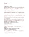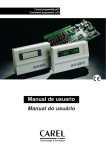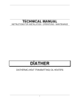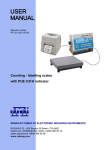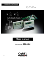
1
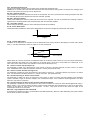
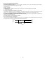
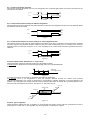
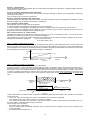
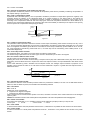
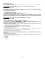
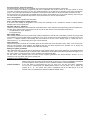
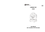
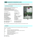
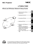
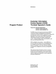
SEQUENCE CONTROLLER
Date: SEPT, 2003
Replaces: 506B-01/04B
User manual
Programme code:
Ref:
SEQ3.04
TABLE OF CONTENTS
1
OPERATING LIMITS………………………………………………………………………………………………………...C
1
FEATURES OF THE PROGRAMME ...........................................................................................................................0
2
USER INTERFACE ........................................................................................................................................................0
2.1
2.2
2.3
2.4
2.5
2.6
KEYBOARD-DISPLAY TERMINAL: FRONT PANEL VIEW WITH FRONT DOOR CLOSED ..............................................................0
SILICONE RUBBER EXTERNAL BUTTONS .........................................................................................................................0
FRONT VIEW WITH FRONT DOOR OPEN ...........................................................................................................................1
USE OF THE BUTTONS ..................................................................................................................................................1
DISPLAY.....................................................................................................................................................................2
FUNCTION INDICATOR LEDS ........................................................................................................................................2
3
LIST OF PARAMETERS ...............................................................................................................................................3
4
ALARM DESCRIPTION................................................................................................................................................9
5
DESCRIPTION OF PARAMETERS............................................................................................................................10
6
CONNECTIONS ...........................................................................................................................................................19
6.1
6.2
7
HARDWARE ARCHITECTURE .......................................................................................................................................19
MAIN BOARD - LAYOUT.............................................................................................................................................20
MEANING OF INPUTS AND OUTPUTS....................................................................................................................22
INSTALLATION OF EPROMS..................................................................................................................................................24
8
CONNECTION OF OPTIONAL BOARDS..................................................................................................................24
8.1
8.2
9
SERIAL PRINTER ........................................................................................................................................................24
CLOCK BOARD ..........................................................................................................................................................24
APPENDIX A: TROUBLESHOOTING .......................................................................................................................25
OPERATING LIMITS
The McQuay sequencer is capable of controlling a system of Chillers or Heat Pumps, installed in a single
system, in order to control the common leaving water temperature of the evaporators, for improved and
complete system management.
The McQuay sequencer can control up to a maximum of 10 units installed in a single system,
The control point is a temperature probe installed in the common leaving water pipe from the units,
reference ELWT (Evaporator Leaving Water Temperature)
The McQuay sequencer also has a second temperature probe CWTR (Cooling Tower Water Return)
capable of controlling the cooling tower steps in the case where some water-condensed refrigerators are
installed in the system (series WHR, WHS, PFS, WHZ, PEH, PFH, WSC, WDC).
In the case where a CTWR probe is installed, the number of units which can controlled is limited,
The sequener can only control a maximum number of 10 devices.
Example:
a)
b)
c)
d)
Up to 10 air-cooled units (ALS, ALR, AGR, ALZ) without any added control requiring the
use of digital outputs.
In the case where cooling tower control is required, the maximum number of units
controlled cannot exceed 10 minus GT,
GT being the number of Tower Steps to be controlled.
In the case where cooling tower control by inverter is required (without added On/Off
steps), the maximum number of units controlled is 10.
In the case where control of a bypass valve on the cooling circuit is required, as well as
tower step control, the maximum number of units that can be controlled is 10 minus GT,
GT being the number of Tower Steps to be controlled.
The system also permits the following functions:
1)
Setpoint Reset: With an external signal of 4-20mA, it is possible to vary the
system’s cooled water control setpoint. 4mA relates to the minimum setpoint value
(St3) and 20mA relates to the maximum setpoint value (St4). A value below 4mA
disables this function.
2)
Load limiter: With an external signal of 4-20mA, it is possible to limit the number of
refrigerators in terms of limiting electrical absorption at certain periods of the day.
The number of units set will be subdivided proportionally in terms of the external
signal set. The system divides the difference between the maximum and minimum
signal (20-4 = 16 mA) by the number of refrigerators set in the controller and the
enables/disables for each increase in signal sent.
eg.: for 8 refrigerators set, we have 16mA : 8= 2mA/refrigerator. Every 2 mA
enables or disables a refrigerator.
3.
Ambient compensation: With the installation of an ambient sensor, it is possible
to vary the setpoint of the cooled water in terms of external air. This option allows
an energy saving in low-load periods.
1
FEATURES OF THE PROGRAMME
The programme allows full management of a refrigerator plant consisting of several refrigerators.
The features of the system are as follows:
display and control of the measured sizes;
possible configuration of the number of refrigerators to be controlled;
LED display of alarms and their audible signals by means of a buzzer;
programming of the configuration parameters and of some operational parameters with access protected by a
password;
modification of the basic operating parameters (setpoints, differentials, alarm thresholds, timers);
LED display of the active functions;
printout of the alarms detected and, at intervals, the state of the main variables of the machine;
by time band programming it is possible to operate the devices controlled by probe 1 from a second setpoint
(secondary) so as to save energy during the programmed hours and days;
- connection to a supervisory/remote controlled assistance serial line according to RS422/RS485 standard
and Carel’s communication protocol.
2
2.1
USER INTERFACE
Keyboard-display terminal: front panel view with front door closed
Figure 1 references
COMPRESSORS
Bar
Bar
°C
°C
°F
°F
FANS
SET 2
SET EXT
1.
2.
3.
4.
External function-indicator LEDs
Rubber external buttons
LED display
Front window
NETWORK
Figure 1
2.2
Silicone rubber external buttons
Figure 2
References Figure 2
1. On/off button: turns the unit on and off. When the unit is on, the LED button is lit (a green colour)
- an unlit LED indicates that the unit is OFF;
- a flashing LED indicates that the unit has been turned off by a supervisor or by remote control, by means of a digital
input;
2. Alarm button: it is used to display the alarms, to reset them manually and to silence the buzzer.
If the button is lit (red), it means that at least one alarm has been detected.
3. The arrow pointing upwards sets the values of the control parameters (not back lit), or to disable manual procedure.
4. The arrow pointing downwards sets the values of the control parameters (not back lit), or to disable manual procedure.
5. Enter button: to scan the messages on the display. The button is continuously lit (yellow light) and indicates that the
power is On.
2.3
Front view with front door open
Figure 3 references
COMPRESSORS
Bar
Bar
°C
°C
°F
°F
FANS
1.
2.
3.
4.
SET 2
SET EXT
NETWORK
Polycarbonate - coated mechanical buttons
Function indicator LEDs
Adhesive polycarbonate
Silicone rubber buttons.
Figure 3
2.4
Use of the buttons
permits display of values detected by the probe ELWT (cooled water) and by probe CTWR (cooling water)
permits access to the values related to the hour counters, to the manual procedure of the devices connected
and to probe setting
gives access to the set of parameters for operating the printer (where required)
permits display of the status of inputs and outputs, both digital and analogue
permits display/programming of the clock (if present) and of related time bands with setpoint variation
permits display and setting of the setpoints
permits setting of the various operating parameters (protections, thresholds), as well as the parameters relating
to unit configuration
permits display of the version of the programme to be applied
The LEDs beside the listed buttons light up when pressed, and remain in this status until any one of the above-mentioned
buttons is pressed.
1
2.5
Display
COMPRESSORS
Bar
Bar
°C
°C
°F
°F
FANS
SET 2
SET EXT
NETWORK
Figure 4
Features
• number of digits: 6
• colour: green
• height: 13mm
• number of side indicator LEDs: 5
• number of LEDs indicating the displayed function: 3+3
2.6
Function indicator LEDs
The 5 LEDs placed beside the display have the following meaning:
1. LED On
at least one refrigerator, controlled by probe ELWT, is enabled;
Flashing LED
at least one refrigerator, controlled by probe ELWT, is in waiting phase, meaning that its operation has
been requested, but it remains off until its internal timers have been elapsed;
LED Off
no refrigerator, controlled by probe ELWT, is enabled;
2. LED On
at least one step of cooling tower, controlled by probe CTWR, is enabled;
LED Off
no step of cooling tower, controlled by probe CTWR, is enabled;
3. LED On
night setpoint is enabled (dual setpoint);
4. LED On
indicates that setpoint variation is coming from an analogue input (external setpoint);
5. LED On
indicates that communication with monitoring network is enabled;
The 6 LEDs placed in the display indicate the unit of measure of the values detected by the two linked probes (settings made
in the programming-code section):
bar
°C
°F
pressure (not used);
temperature in degrees Celsius;
in degrees Fahrenheit
2
3
LIST OF PARAMETERS
All parameters in boldface are described from page 12
In the following tables there are two Default columns: in the right column there are the values determined by McQuay. Default
values are stored in the memory of every system (see page 21). In the left column the user may write his/her own values as
a memo.
Maintenance button
Code
t1
t2
t3
t4
t5
t6
t7
t8
t9
t10
t11
t12
PSt
th
r1
r2
r3
r4
r5
r6
r7
r8
r9
r10
r11
r12
n1
n2
n3
n4
n5
n6
n7
n8
n9
n10
n11
n12
CL1
CL2
CL3
CL3
Description
Default
refrigerator 1 operating hour display
refrigerator 2 operating hour display
refrigerator 3 operating hour display
refrigerator 4 operating hour display
refrigerators operating hour display
refrigerator 6 operating hour display
refrigerator 7 operating hour display
refrigerator 8 operating hour display
refrigerator 9 operating hour display
refrigerator 10 operating hour display
device 11 operating hour display
device 1/valve inverter operating hour display (only if device
1/valve inverter is enabled)
password for access to subsequent parameters
refrigerator operating-hour threshold
reset of refrigerator 1 operating-hour number
reset of refrigerator 2 operating hour number
reset of refrigerator 3 operating hour number
reset of refrigerator 4 operating hour number
reset of refrigerator 5 operating hour number
reset of refrigerator 6 operating hour number
reset of the refrigerator 7 operating hour number
reset of the refrigerator 8 operating hour number
reset of the refrigerator 9 operating hour number
reset of refrigerator 10 operating hour number
reset of device 11 or fan inverter operating hour number
reset of device 1/valve inverter operating hour number
refrigerator 1 manual operation enable
refrigerator 2 manual operation enable
refrigerator 3 manual operation enable
refrigerator 4 manual operation enable
refrigerator 5 manual operation enable
refrigerator 6 manual operation enable
refrigerator 7 manual operation enable
refrigerator 8 manual operation enable
refrigerator 9 manual operation enable
refrigerator 10 manual operation enable
device 11 or fan inverter manual operation enable
device 1/valve inverter manual operation enable
Probe ELWT calibration (cooled water sensor)
probe CTWR calibration (tower water sensor)
probe OAT calibration (ambient sensor)
probe 3 calibration (only if P22=1)
3
DefinedLimits
0÷999999
0÷999999
0÷999999
0÷999999
0÷999999
0÷999999
0÷999999
0÷999999
0÷999999
0÷999999
0÷999999
0÷999999
0
0
0
0
0
0
0
0
0
0
0
0
0
0
0
0
0
0
0
0
0
0
0
0
0
0
0
0
0
0
0÷999
0÷999
0→disable 1→enable
0→disable 1→enable
0→disable 1→enable
0→disable 1→enable
0→disable 1→enable
0→disable 1→enable
0→disable 1→enable
0→disable 1→enable
0→disable 1→enable
0→disable 1→enable
0→disable 1→enable
0→disable 1→enable
0→disable 1→enable
0→disable 1→enable
0→disable 1→enable
0→disable 1→enable
0→disable 1→enable
0→disable 1→enable
0→disable 1→enable
0→disable 1→enable
0→disable1→enable
0→disable 1→enable
0→disable 1→enable
0→disable 1→enable
-5.0÷5.0
-5.0÷5.0
-5.0÷5.0
-5.0÷5.0
Units of
measurement
h
h
h
h
h
h
h
h
h
h
h
h
hx1000
°C/F°/
°C/F°/
°C/F°
°C/F°
Printer button
Description
Code
Pr1
Pr2
Default
immediate printing request (only if P42=1)
cyclic printing time setting (only if P42=1)
0
60
Defined Limits
Units of
measurement
0→disable 1→enable
0÷999
min
I/O button
Description
Code
Ai1
Ai2
Ai3
Ai4
i1
i2
i3
i4
i5
i6
i7
i8
i9
i10
i11
i12
Ao1
Ao2
o1
o2
o3
o4
o5
o6
o7
o8
o9
o10
o11
Default
Temperature of water controlled by sensor ELWT (evaporator)
Temperature of water controlled by sensor CTWR (tower)
Ambient temperature (OAT sensor)
Remote on/off status
Refrigerator 1 alarm relay status
Refrigerator 2 alarm relay status
Refrigerator 3 alarm relay status
Refrigerator 4 alarm relay status
Refrigerator 5 alarm relay status
Refrigerator 6 alarm relay status
Refrigerator 7 alarm relay status
Refrigerator 8 alarm relay status
Refrigerator 9 alarm relay status
Refrigerator 10 alarm relay status
Device 11 alarm relay status
low pressure/flow regulator alarm status
system flow regulator status
display of device 1/valve inverter status
refrigerator 1 status
refrigerator 2 status
refrigerator 3 status
refrigerator 4 status
refrigerator 5 status
refrigerator 6 status
refrigerator 7 status
refrigerator 8 status
refrigerator 9 status
refrigerator 10 status
refrigerator 11 status
Defined limits
-99÷99.9
-99÷99.9
-99÷99.9
0→off; 1→on
0→off; 1→on
0→off; 1→on
0→off; 1→on
0→off; 1→on
0→off; 1→on
0→off; 1→on
0→off; 1→on
0→off; 1→on
0→off; 1→on
0→off; 1→on
0→off; 1→on
0→off; 1→on
0÷10.0
0÷10.0
0→off; 1→on
0→off; 1→on
0→off; 1→on
0→off; 1→on
0→off; 1→on
0→off; 1→on
0→off; 1→on
0→off; 1→on
0→off; 1→on
0→off; 1→on
0→off;1→on
Units of
measurement
°C/F°/bar
°C/F°/bar
°C/°F/bar
volt
volt
Clock button
Code
C1
C2
C3
C4
C5
PSC
C6
C7
C8
C9
Description
Default
hour display
minute display
day display
month display
year display
password that allows access to subsequent parameters
hour setting
minute setting
day setting
month setting
4
0
0
0
0
0
Defined Limits
0÷23
0÷59
1÷31
1÷12
0÷99
0÷999
0÷23
0÷59
1÷31
1÷12
Unit of
measurement
h
min
h
min
5
C10
C11
C12
C13
C14
C15
C16
C17
C18
C19
C20
C21
C22
year setting
band start hour with secondary set
band end hour with secondary set
Sunday with secondary set
Monday with secondary set
Tuesday with secondary set
Wednesday with secondary set
Thursday with secondary set
Friday with secondary set
Saturday with secondary set
half a day exclusion
exclusion start
exclusion end
0
0
24
0
0
0
0
0
0
0
0
0
0
0÷99
0÷23
0÷24
0→no;
0→no;
0→no;
0→no;
0→no;
0→no;
0→no;
h
h
1→yes
1→yes
1→yes
1→yes
1→yes
1→yes
1→yes
0÷7
C11÷C12
C21÷C12
h
h
Setpoint button
Code
Description
Def
ault
Sd1
St1
St2
Si1
Si2
PSS
St3
St4
St5
St6
St7
d1
d2
d3
d4
Sr1
Sr2
Sr3
Sr4
display of probe ELWT current setpoint
local probe ELWT setpoint setting
local probe CTWR setpoint setting (only if there are tower steps)
device 1/valve inverter setpoint setting
fan inverter setpoint setting
password for access to subsequent parameters
probe ELWT minimum setpoint setting
probe ELWT maximum setpoint setting
probe CTWR minimum setpoint setting
probe CTWR maximum setpoint setting
dual setpoint setting
probe ELWT differential setting
probe CTWR differential setting
device 1/valve inverter differential
fan inverter differential setting
device 1 inverter step
device 1 inverter deviation setting
device 1 inverter minimum aperture
device 1 inverter minimum aperture always applied
SH1
SL1
SH2
SL2
dH1
dL1
dH2
dL2
SC
dC
dt
evaporator high water temperature threshold (probe ELWT)
evaporator low water temperature threshold (probe ELWT)
tower high water temperature threshold
tower low water temperature threshold
evaporator high water temperature alarm delay
evaporator low water temperature alarm delay
tower high water temperature alarm delay
tower low water temperature alarm delay
external area temperature compensation setpoint
external area temperature compensation differential
external area temperature compensation delta
6
Defined Limits
7.0
30.0
2.5
16.0
0
4
10.0
25.0
45.0
6.0
3.0
1.0
1.0
2.0
0.2
0
0
0
30.0
3.0
50
20
30
3
3
30
35.0
5.0
2.0
St3÷St4
St3÷St4
St5÷St6
St3÷St4
St5÷St6
0÷999
-99÷99.9
-99÷99.9
-99÷99.9
-99÷99.9
-99÷99.9
0÷20.0
0÷20.0
0÷20.0
0÷20.0
0÷10.0
0÷20.0
0÷10.0
0→disable
1→enable
-99÷99.9
-99÷99.9
-99÷99.9
-99÷99.9
0÷999
0÷999
0÷999
0÷999
-99÷99.9
-50.0÷50.0
-99÷99.9
Unit of
measurement
°C/°F/bar
°C/°F/bar
°C/°F/bar
°C/°F/bar
°C/°F/bar
°C/°F/bar
°C/°F/bar
°C/°F/bar
°C/°F/bar
°C/°F/bar
°C/°F/bar
°C/°F/bar
°C/°F/bar
°C/°F/bar
Volt
°C/°F/bar
Volt
°C/°F/bar
°C/°F/bar
°C/°F/bar
°C/°F/bar
min
min
min
min
°C/°F/bar
°C/°F/bar
°C/°F/bar
Programming button
Code
Description
Default
Defined Limits
Unit of
measurement
PSn
P1
password for access to programming section
probe ELWT type (refrigerated water control)
0
2
P4
P5
P6
P10
P11
P12
P13
P14
number of devices controlled by probe ELWT
number of devices operating in the event of probe ELWT failure
number of chokes
minimum refrigerator start-up time
minimum refrigerator stop time
minimum time between start-ups of different refrigerators
minimum time between start-ups of same refrigerator
regulation with neutral zone or lateral band - probe ELWT circuit
5
2
0
180
180
300
360
0
P17
P18
P19
minimum refrigerator start-up request time
minimum refrigerator start-up stop time
refrigerator rotation enable
20
10
2
P22
P23
P24
air temperature probe enable
Setpoint ambient compensation enable
probe CTWR type (set 0 unless tower controlled)
1
0
2
P27
P28
P29
number of Cooling Tower steps
minimum time between cooling tower step start-ups
regulation with neutral zone - cooling circuit
0
2
0
0÷999
0→absent
2→passive
0÷11
0÷P4
0÷3
0÷999
0÷999
0÷999
0÷999
0→neutral z.
1→lat. band
0÷999
0÷999
0→ disabled
1→FIFO
2→on time
0→disable 1→enable
0→disable 1→enable
0→absent
2→passive
0÷11
0÷999
0→neutral z.
P32
P33
P34
P35
P36
P37
time between Tower step start-up requests
time between Tower step stop requests
Tower step rotation enable
Tower conrol fan inverter enable
flow regulator alarm delay
self-start procedure enable
5
5
1
0
40
1
s
0÷999
s
0÷999
0→disable 1→enable
0→disable 1→enable
s
0÷999
0→disable 1→enable
7
s
s
s
s
s
s
s
P39
P40
P41
P42
P43
P44
P45
P46
P47
°C or °F display
remote on/off enable
clock enable
printer enable
identification number
automatic or manual reset alarms
alarm relay operation delay
ON/OFF button disable with machine ON
serial communication baud-rate
0
1
1
0
1
0
0
0
1
P61
P62
machine stop mode
cold/hot
0
0
0→°C;→°F
0→disable 1→enable
0→disable 1→enable
0→disable 1→enable
0÷999
0→autom. 1→manual
min
0÷999
0→disable 1→enable
0→1200 1→2400
2→4800 3→9600
4→19200
0→full
1→partial
0→cold
1→hot
Info button
Code
If1
Description
Def
ault
programme version
8
Defined Limits
Unit of
measurement
4
ALARM DESCRIPTION
For description of how to control Alarms, see parameter P44 on page 18
Alarm button
Code
AL 1
AL 2
AL
AL
AL
AL
AL
AL
AL
AL
AL
AL
AL
3
4
5
6
7
8
9
10
11
12
13
AL
AL
AL
AL
AL
AL
AL
AL
AL
AL
AL
AL
AL
AL
AL
14
15
17
18
19
20
21
22
23
24
25
26
27
28
29
AL 30
AL 31
AL 32
AL 33
AL 34
AL 35
Description
Refrigerator 1 operating hours threshold exceeded
Refrigerator 2 operating hours threshold
exceeded
Refrigerator 3 operating hours threshold exceeded
Refrigerator 4 operating hours threshold exceeded
Refrigerator 5 operating hours threshold exceeded
Refrigerator 6 operating hours threshold exceeded
Refrigerator 7 operating hours threshold exceeded
Refrigerator 8 operating hours threshold exceeded
Refrigerator 9 operating hours threshold exceeded
Refrigerator 10 operating hours threshold exceeded
Device 11 operating hours threshold exceeded
Bypass inverter/valve hours threshold exceeded
Eprom not operational
Probe ELWT not connected or not operational
Probe CTWR not connected or not operational
Absence of flow alarm
Refrigerator 1 alarms
Refrigerator 2 alarms
Refrigerator 3 alarms
Refrigerator 4 alarms
Refrigerator 5 alarms
Refrigerator 6 alarms
Refrigerator 7 alarms
Refrigerator 8 alarms
Refrigerator 9 alarms
Refrigerator 10 alarms
Device 11/fan inverter lock
Probe ELWT high temperature threshold
exceeded
Probe ELWT low temperature threshold
exceeded
Probe CTWR high temperature threshold
exceeded
Probe CTWR low temperature threshold
exceeded
Number of refrigerators selected exceeds the
outputs actually available
Ambient Probe 3 not connected or not
operational
Clock board failure or not connected
Effect
Indication
Indication
Check
Threshold and number of hours
Threshold and number of hours
Indication
Indication
Indication
Indication
Indication
Indication
Indication
Indication
Indication
Indication
Indication
Total refrigerator lock
Indication
Indication
Indication
Indication
Indication
Indication
Indication
Indication
Indication
Indication
Indication
Indication
Threshold and number of hours
Threshold and number of hours
Threshold and number of hours
Threshold and number of hours
Threshold and number of hours
Threshold and number of hours
Threshold and number of hours
Threshold and number of hours
Threshold and number of hours
Threshold and number of hours
Reset factory values and stop
MicroTechll. If when starting up again
AL13 still on, replace board
Connections of probe ELWT
Connections of probe CTWR
Wiring of the digital input 12
Wiring of the digital input 1
Wiring of the digital input 2
Wiring of the digital input 3
Wiring of the digital input 4
Wiring of the digital input 5
Wiring of the digital input 6
Wiring of the digital input 7
Wiring of the digital input 8
Wiring of the digital input 9
Wiring of the digital input 10
Wiring of the digital input 11
Check high temperature threshold
Indication
Check low temperature threshold
Indication
Check high temperature threshold
Indication
Check low temperature threshold
Indication
Indication - check number of
refrigerators selected
Wiring of ambient probe
Time band lock
Board connection
9
5
DESCRIPTION OF PARAMETERS
t1÷t12 - refrigerator hour display
These parameters indicate the number of operating hours of the individual refrigerators. When displaying these parameters, the
identification number code alternates, every two seconds, with the number of operating hours of the refrigerator corresponding to the
code.
T
1
NUMBER OF HOURS:
IDENTIFICATION CODE
0 3 5
MOST SIGNIFICANT PART
1
7 8
LEAST SIGNIFICANT PART
When the number of operating hours of the individual refrigerator exceeds the operating hour threshold (th), indication is given by
alarms AL 1 ÷ AL 12. Caution: when the analogue outputs dedicated to the fan inverter and to the device 1/valve inverter are used
(parameters t11 and t12), the displayed operating hours refer to the calculation with the corresponding outputs at a value higher
than 0 volt.
th - operating hour threshold
When the operating hours of the refrigerator exceed this value, an alarm signal is produced, indicating that maintenance of
the refrigerator is needed. If this parameter is given the value 0, this control is automatically excluded.
Caution. setting must be made in h x 1000.
n1÷n12 - manual operation of the refrigerators
These parameters permit manual activation of the individual device, without the help of timers, rotation, and independently of the
values measured by the probes. The sole support of control in manual operation is alarm management. Manual activation of the
inverter devices makes it possible to force their analogue outputs to the value of 10 volts. The manual procedure can be activated
only if the unit is OFF. Therefore, all the parameters n1÷n12 are not enabled if the unit is ON. The flashing LED of the menu button
indicates that the manual procedure is enabled. If, after pressing the menu button, the “Up” button or “Down” button, is kept pressed
down for more than 2 seconds, the whole manual procedure is disabled. In any case, the manual procedure is automatically
completed after 30 minutes.
CL1, CL2, CL3 - probe calibration
These parameters allow software calibration of the probes ELWT, CTWR and OAT. The value given to these parameters is
actually added (positive value) or subtracted (negative value) to the measurements detected by the respective probes. The
offset of calibration may be changed from -5.0 to +5.0 with the accuracy of one decimal point. The CL3 parameter is visible
only when the relative probe OAT (P22=1) has been selected.
Pr1 - immediate printing request
This parameter allows the printout of the unit ‘s main data such as: values detected by the probes, active devices and the
setpoints programmed.
Pr2 - cyclic printing time
This parameter indicates the cyclic printing time, i.e. the T period between one printout and the next.
Ai3 - meaning of the analogue input B3 (see figure 30).
This parameter allows the display of the value detected by the third analogue input that can be:
- variable setpoint by using a potentiometer (P21=1);
- if the parameter is P21=0 and P22=1, then the detected value represents the temperature probe of the ambient air
(necessary for controlling the setpoint compensation).
i11 - digital input ID11 (see figure 30).
This parameter allows the display of the status of digital input no.11. This input can be:
- the shutdown of device no.11 if it has been previously selected;
- the shutdown of the fan inverter if device no.11 has not been selected.
C11=C12 - selection of the start and end time of the reduced setpoint.
The parameter C11 allows the start of time bands with reduced setpoint to be set; the parameter C12 makes it possible to set
the end hour. Examples:
- Time band during the day. C11=12, C12=16: the reduced setpoint is enabled from 12:00 a.m. to 3:59 p.m.;
- Time band between two successive days. C11=14, C12=9: the reduced setpoint is enabled from 2:00 p.m. to 8:59 a.m. of
the following day;
- C11=C12: the reduced setpoint is enabled throughout the whole day (24 hours).
IMPORTANT: Never set the value C11=C12=0.
C20= selection of the day with time band exclusion.
The parameter allows time band exclusion with secondary setpoint for a selected day. The start hour (C21) and end hour
(C22) are programmable. The data that can be selected are the following:
0
time band exclusion not enabled;
1
time band exclusion with secondary set for the day of Monday;
2
time band exclusion with secondary set for the day of Tuesday;
3
time band exclusion with secondary set for the day of Wednesday;
4
time band exclusion with secondary set for the day of Thursday;
5
time band exclusion with secondary set for the day of Friday;
6
time band exclusion with secondary set for the day of Saturday;
7
time band exclusion with secondary set for the day of Sunday.
C21 - time band exclusion start.
The start of time band exclusion with secondary set is required (see parameter C20).
10
C22 - time band exclusion end.
The end of time band exclusion with secondary set is required (see parameter C20).
Caution: do no enable at the same time the time bands with reduced setpoint and regulation of setpoint from analogue input
because both options have priority over the setpoint set.
St3, St5 - minimum setpoint
They establish the minimum value that can be set for the setpoints. The user is prevented from entering a setpoint lower than
the value St3( ELWT) and a setpoint lower than the value St5. (CTWR)
St4, St6 - maximum setpoint
These points establish the maximum value that can be set for the setpoints. The user is prevented from entering a setpoint
higher than the value St3( ELWT) and a setpoint higher than the value St5. (CTWR).
St7 - secondary setpoint
Allows setting of secondary setpoint, that is valid when time bands are enabled.
d1, d2 - device differentials
These parameters establish the values of the differentials of the devices managed by probe ELWT and CTWR .
setpoint
differential
Figure 5
d3, d4 - inverter differentials
In addition to the setpoint of the relevant circuit, the differential is the working value for calculating the inverter end of stroke
point, i.e. the value measured to which an output of 10 volts corresponds.
Volt
10
0
setpoint
differential
value measured
Figure 6
Where either d3 or d4 are concerned, the differential refers to the device 1/valve inverter or to the fan inverter respectively.
These parameters are visible only if the outputs for the inverter (P20=1 and P35=1) are provided for. Furthermore, in the
case of the circuit 1/valve inverter, the side band control must be selected (P14=1).
Sr1 - device 1 inverter step (see figure 14).
The parameter is visible only if the presence of the inverter on device 1 has been selected, and also control is in neutral
zone. It establishes the increase and decrease of device 1 inverter (see parameter P20).
Sr2 - device 1 inverter deviation (see figure 14).
The parameter is visible only when the presence of the inverter on device no. 1 has been selected, and control is in neutral
zone. It is essential for calculating device no. 1 inverter connection (see parameter P20).
Sr3 - minimum opening of device 1/valve inverter.
The parameter is visible only when the presence of the inverter on device no.1/valve has been selected. This parameter
makes it possible to apply a minimum voltage to the inverter/valve output. If the conditions require application of a value
below Sr3, this value is compulsory.
Sr4 - minimum opening of device 1/valve inverter continuously applied.
The parameter is visible only when the presence of the inverter on device no.1/valve has been selected (parameter P20). If
SR4 is equal to 1, the minimum opening of device 1/valve inverter (parameter Sr3) is applied even in case of an alarm being
present on this device or when (if P14=0) compressor 1 is OFF. Only when the unit is OFF does the output of the
inverter/valve remain at 0 in all cases.
SH1, SH2 - high temperature alarm threshold
It represents the threshold of high of probe ELWT and CTWR respectively. When the value detected by the probe exceeds
the set value, the alarm is activated.
11
SL1, SL2 - low temperature alarm threshold
It represents the threshold of low of probe ELWT and CTWR respectively. When the value detected by the probe falls below
the set value, the alarm is activated.
SC, dC, dt - setpoint, differential and compensation delta
See parameter P23.
P1, P24 - probe type
The parameters make it possible to specify the type of probes used. The following selections are available.
0 probe is absent;
2 temperature NTC probe;
P4 - number of refrigerators controlled by probe ELWT
The parameter represents the number of refrigerators controlled by probe ELWT. The number of refrigerators may range
from 0 to 11. If 11 devices are selected, it is not possible to connect any cooling tower step to the secondary circuit.
P5 - number of refrigerators operating with probe ELWT out of order
In the case where the alarm of probe ELWT is found to be broken or not connected (AL14), parameter P5 indicates the
minimum number of refrigerators ON.
P9 - choke operation in full/part mode (not enabled)
P10 - minimum refrigerator operating time
This sets the minimum refrigerator operating time (in seconds). As a consequence, when enabled, the devices must remain ON
for the same length of time as the one set by the above-mentioned parameter.
ON
OFF
ON
OFF
connection
request
device
P10
Figure 7
12
P11 - minimum refrigerator stop time
This sets the minimum refrigerator stop time. The refrigerators are not started again unless the minimum time set from the
last stop time has elapsed.
ON
OFF
ON
OFF
connecti
on
device
P11
Figure 8
P12 - minimum time between startups of different refrigerators
This represents the minimum time that must elapse between the startup of one refrigerator and the next. This parameter allows
simultaneous starts to be avoided.
device 1
ON
OFF
device n
ON
OFF
P12
Figure 9
P13 - minimum time between successive startups of same refrigerator device
This sets the minimum time that must elapse between two startups of the device, regardless of the measurement detected
and of the setpoint. This parameter makes it possible to limit the number of startups per hour. For example, if the maximum
allowed number of connections is equal to 10, it is only necessary to set a value of 360 seconds to guarantee this limit is
observed.
ON
OFF
connecti
on
ON
OFF
device
P13
Figure 10
P14, P29 regulation with “lateral band” or “neutral zone”
These parameters indicate the activation mode of the refrigerators enabled.
In lateral band the refrigerators are positioned proportionally within the controlled differential.
Example:
dev. 1
setpoint
dev. 2 dev. 3
differential
3 devices
on a single circuit
value detected
Figure 11
In neutral zone there is a zone where no refrigerator is activated or deactivated.
The activation point of the refrigerators is when the measure detected exceeds the neutral zone (measure
detected>set+differential). The number of refrigerators to be activated is variable, depending on the time elapsed in this
condition. The refrigerators are stopped when the measure detected falls below the neutral zone (measure detected <set),
and in this case too it depends on the time. See timers P17, P32 and P18, P33.
connection
neutral zone
setpoint
dev. 1
dev. 2
dev. 3
dev. 2
dev. 1
differential
value measured
dev. 3
deactivation
Figure. 12
P15, P30 - type of regulation
These parameters indicate the type of regulation of circuits ELWT and CTWR, and are valid only if lateral band control is
selected (P14=1 and/or P29=1). The regulation may be Proportional or Proportional + Integral.
13
P16, P31 - integration time
These parameters indicate the integration time of circuits ELWT and CTWR, if a Proportional + Integral regulation has been
selected (P15=1 and/or P30=1).
P17, P32 - minimum refrigerator startup request time
These parameters allow the setting of the time between successive requests for startup of the refrigerators controlled by
probes ELWT and CTWR.
They are present only if control is in neutral zone.
P18, P33 - minimum refrigerator stop request time
These parameters allow the setting of the time between successive requests for stop of the refrigerators controlled by probes
ELWT and CTWR. They are present only if control is in neutral zone.
P19 - refrigerator rotation enable
This parameter allows the rotation type to be selected
0= rotation disabled: last refrigerator to be started up is first to be stopped.
1= "FIFO" rotation: first refrigerator to be started up is first to be stopped; machines are stopped in order of startup.
2= "in-time" rotation: first refrigerator to be started up is the one with the lowest number of operating hours, the first to be
stopped is the one with the highest number of operating hours.
P20 - selection of device no. 1/valve inverter
This parameter enables the presence of the inverter on device no.1 of circuit 1, controlled by probe 1, or of a 0-10 Volt valve,
depending on the presence of neutral-zone or lateral-band regulation.
This is displayed if P1>0 and P4>0 and if chokes (P6>0) and Neutral Zone (P14=0) have not been enabled at the same time.
Therefore the parameter is displayed if:
P1>0, P4>0, P6=0, P14=0;
P1>0, P4>0, P6>0, P14=1.
case 1 - presence of lateral-band regulation
Control involves the setting of a setpoint (SI1) and a differential (d3). When the value detected by probe 1 is lower than or the
same as the value of the valve setpoint, there are 0 volts at the output dedicated to this device. As the value detected by
probe 2 deviates from the set point, the analogue output increases in proportion to the deviation until it reaches 10 volts when
the value detected is the same as or higher than the setpoint + differential.
Volt
10
setpoint
device
0
differential
device 1
value detected by
probe 1
Figure 13
case 2 - presence of neutral-zone regulation
Control requires the setting of a deviation (Sr2) from the setpoint.
The output of device 1 inverter increases when the reading of probe 1 exceeds the value of the neutral zone setpoint (St1) +
deviation of device 1 inverter (Sr2). The decrease takes place when the probe 1 reading is below the value of the neutral
zone setpoint. In the zone included between the neutral zone set point and the neutral zone setpoint + deviation of the device
1 inverter, the inverter output does not change at all; for this reason the zone is called inverter neutral zone. The output of the
inverter increases/decreases at each cycle of the programme, about every second, of the value defined as inverter step
(Sr1).
neutral zone
devices
setpoint
neutral zone
differential neutral
zone devices
device 1 inverter
deviation
inverter decrease zone
inverter neutral
zone
value detected by
probe 1
inverter increase zone
value detected by
probe 1
Figure 14
Caution: when device no.1/valve inverter is enabled and regulation takes place with neutral zone, activation of the devices
occurs as follows:
- device no.1, which is controlled by the inverter, is activated as soon as startup is requested;
- if the request remains, the output of device no.1 inverter is increased;
- if the request is still present, and the output of the inverter reaches 10 Volts, the other devices are requested, one at a
time, with rotation (if selected) and according to the timers.
The stop stage occurs as follows:
- the inverter output is decreased;
- when the inverter output has already reached 0 Volts, the other devices are stopped, one at a time, according to the
timers and rotation;
- the last device that is stopped is no.1.
14
P21 - function not enabled
P22 - external air temperature probe enable (see figure 30)
This parameter enables the presence of an external air temperature probe with the possibility of effecting compensation of
the setpoint relating to probe ELWT.
P23 - probe 1 compensation enable
If parameter P22 is activated (P22=1), then it is possible to enable the procedure of compensation (positive or negative). This
procedure allows the setpoint of the refrigerated water to be varied according to the values read by the external air
temperature probe. More precisely, a proportional quantity is added (or deducted) to the setpoint of the primary circuit
according to the compensation delta set and when varying the external air temperature between two values defined by a
setpoint and a compensation differential. The maximum value that can be added (or deducted) to the setpoint of the primary
circuit is equal to the compensation delta (see figure below).
setpoint
circuit
1
compensation
delta
compensation differential
compensation setpoint
external air
temperatur
e
Figure 15
P27 - number of cooling tower steps
This parameter makes it possible to define the number of tower steps controlled by probe CTWR. The steps can vary from 0
to 11, but this parameter depends also on the number of refrigerators controlled by probe ELWT (parameter P4). This means
that if no refrigerator controlled by probe ELWT is connected, the Tower steps controlled by probe CTWR can be 11 at most,
but, if the refrigerators controlled by probe ELWT are 11, no Tower step can be controlled by probe CTWR (case of 11 aircondensed refrigerators).
P34 – tower step rotation selection
The parameter allows the rotation of the tower steps controlled by probe CTWR.
The rotation being implemented is of the “FIFO” type: the first to be started up is the first to be stopped
P35 - fan inverter enable for tower control
The fan inverter can be enabled by this parameter.
Enabling the control of fan inverter involves setting a setpoint inverter (SI2) and a differential inverter (d4). When the value
detected by probe CTWR is less than or equal to the value of the setpoint inverter, the output dedicated to this device shows
0 volts.
As the value detected by probe 2 deviates from the setpoint inverter, the analogue output increases in proportion to the
deviation until it reaches the value of 10 Volts when the value measured is equal to or greater than the setpoint inverter +
differential inverter.
Volt
1
0
0
inverter
setpoint
differential
inverter
Figure 16
value detected by
probe 2
P37 - autostart procedure enable
This allows the selection of the autostart procedure. When the procedure is enabled, if the unit is in the ON status before a
black-out, after the black-out period, the ON status is automatically restored.
P38 - not enabled
P39 - °C or °F
Defines the unit of measurement.
0 temperature in degrees Centigrade
1 temperature in degrees Fahrenheit
When changing from one measurement system to the other, automatic conversion of the values measured on the analogue
inputs is given.
Caution: the automatic conversion does not take place for the parameters. The user must update them when changing them
P40 - remote on/off enable
If the value of the parameter is 1, it is possible to use the fourth analogue input (B4) to start up or stop the unit:
contact open
→ unit off
contact closed → unit on
P41 - clock enable
In case the clock board is used, this parameter must be set at 1, otherwise it is not possible to have access to the clock section.
P42 - printer enable
In case of connection to a serial printer this parameter must be 1, otherwise it is not possible to have access to the printer
section.
15
P43 - identification number
The parameter allows the setting of the unit identification number (useful only in case of connection to a system of
supervision and/or remote assistance).
P44 - alarms with automatic or manual reset
P44=0 ⇒ automatic. In the event that one or more alarm conditions are detected, these are indicated by:
red LED below “alarm” key lit;
- buzzer activated;
- alarm relay (switching relay normally on) opens
Pressing “alarm” key silences the buzzer and the alarm codes are displayed. If the causes of the alarms are reset, the status
of the indication alarm relays becomes:
- alarm relay disconnects (switches from NO a NC);
- the buzzer, if it has not been disconnected by pressing “alarm” button, is de-activated;
- red LED below “alarm” button flashes.
If in this situation new alarms are operated, the initial situation is shown.
The flashing red LED tells the user that there have been alarms during the day and that now these have already been
restored. The codes of the alarms remain, however, in the memory, so that, by pressing the “alarm” button, they can be
displayed. If after having displayed them, the “alarm” button is pressed again, they are cancelled and the red LED also finally
goes out.
P44=1 ⇒ manual. In the event that one or more alarms are detected, they are indicated by:
- red LED below “alarm” button lit;
- buzzer activated;
- alarm relay (switching relay normally on) opens
Pressing the “alarm” button silences the buzzer and alarm codes are displayed.
If the causes of the alarms are reset, the flashing red LED tells the user that there have been alarms during the day, and that
they have already been restored. In this situation the alarm relay remains with contact NC closed to indicate fault.
If in this situation new alarms are operated, the initail situation is shown.
Cancellation is made by pressing “alarm” during alarm message display. If the causes have actually been cancelled, the
status of the indication devices becomes:
- alarm relay disconnects (switches from NO a NC);
- the buzzer, if it has not been silenced yet by pressing “alarm” button, is de-activated;
- red LED below “alarm” button is disconnected.
On the other hand, if the causes of the alarms have not been cancelled, the initial situation is shown.
P45 - delay in activating alarm relay
The parameter allows the user to set a delay time (in minutes) between the activation of any alarm and the start of the
indication relay (digital output no.11). If P45 is set at 0, alarm relay activation is immediate.
P46 - “On-Off” button disable from refrigerator ON
This parameter makes it possible to disable the operation of the “on-off” button for disconnecting the unit. If parameter 46 is
set at 0, the “on-off” button can either connect or disconnect the unit; if parameter 46 is set st 1, the “on-off” button can only
connect the unit.
P47 - serial communication baud-rate
This parameter permits the serial communication baud-rate to be selected. When the RS485 serial board is connected it is
possible to choose the data transmission speed :
0 1200 baud
1 2400 baud
2 4800 baud
3 9600 baud
4 19200 baud.
16
P61 - not enabled
P62 - cold/hot
With this parameter it will be possible to decide whether the devices belonging to circuit ELWT are used to produce cold
(P62=0; e.g. refrigerators) or hot (P62=1; e.g. heat pumps).
•
•
proportional band
cold
1
2
differential
set
•
•
•
•
n
pressure or
temperature
•
•
1
pressure or
set temperature
neutral zone
warm
request switch on
devices
request switch on
devices
differential
2
differential
neutral zone
cold
set
proportional band
warm
n
set
pressure or
temperature
request switch off
devices
differential
pressure or
temperature
request switch off
devices
AL13 - EEPROM not operating
In case of an EEPROM failure (chip within the device) this message is indicated.
Skilled engineers are required.
17
AL14, AL15, AL34 - probe not operating
The relevant probe is broken or not connected. Check the wiring and functional capacity of the probe.
If AL14 is present, the devices programmed with the P5 parameter are forced to start up, and the inverter of device
no.1/valve, if enabled, is forced to 10 volts. The remaining devices can be switched on according to the value measured by
probe 1. If AL15 is present all the devices connected to circuit 2 are forced to switch on and the fan inverter is forced to 10 volts.
If AL34 is present, the compensation (if enabled) does not operate. These alarms can only be reset manually, and so they do
not reset until the user presses the alarm button on the pCO terminal in order to clear the alarms.
AL17 - flow regulator
Alarm message AL17 indicates water flow alarm.
AL33 - selected refrigerator number incorrect
If the sum of the number of refrigerators of the primary and secondary circuit exceeds the number of outputs actually
available, alarm AL33 is generated.
PSt, PSC, PSS, Psn - password
These four codes listed refer to the Passwords of the Maintenance, Clock, Setpoint and Programming branches respectively.
For each of the sections listed, the number to be set in order to have access to the subsequent parameters is:
- xxx (Maintenance, Clock, Setpoint);
- xxx (Programming).
Main display: Menu
After pressing the Menu button the probe ELWT reading is displayed on the left side of the display, whereas on the right side
of the display the probe CTWR reading is displayed. If one of two probes has not been selected (P1=0 and/or P24=0), the
symbol “----” appears instead of the reading. The LED located on the left of each display lights up beside the unit of
measurement (ºC , ºF) corresponding to the type of probe selected.
Initial Lamp-Test
Whenever the pCO is powered up, the display lights up all its LEDs and shows the figures “8.8.8. 8.8.8.” for a few seconds.
After the Lamp-Test the probe readings are displayed and only the LEDs required for the operation are lit. During this
procedure it is possible to check whether all the LEDs are operating.
Setting of negative parameters
Many parameters that can be set from the terminal may have negative values. When these parameters are included between
“-99” and “-10” it is impossible to set the decimal value. Therefore the whole value without decimal is always accepted. From
the control monitor, on the other hand, it is also possible to set the decimal value.
For this reason, when selecting from the control monitor negative parameters with values between -99 and -10, it is
necessary to set only values with 0 as the decimal part.
Installation of the Default Values
_
automatic installation: in the software a control is implemented that carries out automatic installation of the
default values when the initial programme startup is carried out or when the EPROM is substituted
for another different version (check the version and date indicated on the EPROM label);
manual installation:
if the user wants to reprogramme the unit, he must put it into the OFF status. Afterwards
he must press simultaneously the MENU+PROG buttons until the letters “rST 0” appear. By
pressing 5 or 6, the symbol “8.8.8. 8.8.8.” is displayed and all the LEDs stay lit for a few
seconds and in the meantime the software installs the default values.
18
6
CONNECTIONS
For an exhaustive description of the hardware and of the installation procedure please refer to the Microtech II “Installation
and Usage manual", available on request.
6.1
Hardware architecture
Terminal
with LED or LCD display
programme eprom
Connector
for RS422
serial board
Connection cable
Standard cable for RS422 printer
(not supplled)
Connector
for clock board
Printer (not supplied)
Main board
with screw or plug-in terminals
Figure 17
The hardware architecture is defined as follows:
1. A TERMINAL with display, keyboard and LEDs. The connection of the terminal to the main board is not necessary for
the controller operation; it can be used for the initial programming of the basic parameters.
2. A MAIN BOARD with the set of terminals necessary for connection to controlled devices.
3. Connection cable between terminal unit and main board.
4. Connection cable between terminal unit and serial printer (to be provided by the customer).
5. Serial printer (to be provided by the customer).
19
6.2
Main board - Layout
Below is a description of the sequencer main board with reference to the basic layout.
8
6
G
G0
7 1J
1
4
1
14
7
J9 J8
15
9 1J
2
19
17
18
0 2J
1 2J
1
2 2J
1
6J
NO 8
C8
-- - -- NO 7
C7
-- - -- N06
C6
-- - -- N013
C 13
1
C1
NO 1
-- - -- C2
NO 2
1
5J
9
1
ID C M 1
ID 5
ID 4
ID 3
ID 2
ID 1
1
4J
NO 11
C 11
NC 11
-- - -- - NO 10
C 10
NC 10
-- - -- - NO 9
C9
NC 9
1
ID C M 2
ID 1 0
ID 9
ID 8
ID 7
ID 6
J14
1
4 2J
11
B6
A V SS
B5
B4
A V SS
B3
B2
A V SS
B1
3J
ID 1 1 -2 2 0 Va c
ID 1 1 -2 4 Va c
ID 1 1 -C o m
- - -- - -- ID 1 2 -C o m
ID 1 2 -2 4 Va c
ID 1 2 -2 2 0 Va c
2J
J 15
VG 0
VG 1
Y1
Y0
B8
+ 2 4Vc c
B7
5
16
3
13
1
1J
8 1J
J29 J28
C3
NO 3
-- - -- C4
NO 4
-- - -- C5
NO 5
-- - -- C 12
NO 12
12
10
9
1
Figure 18
The main board is the basic core of the controller ; inside it 3 different parts can be identified:
•
•
•
the microprocessor and memories that control the unit
the terminal boards that permit interface with the refrigerators controlled to be set up
the connectors that permit interface with the remote terminal, the real-time clock board, and the local and monitoring
network to be set up.
20
Figure 18 references, page 22
10W (see note on page 28)
Power supply connector 24V~50-60 Hz 15VA or 24V
Telephone-type connector for connection to the user terminal (MMI-Man Machine Interface)
Real-time clock board (optional)
RS422/RS485 optoinsulated board (optional) for connection to a monitoring remote assistance serial line
Pin strip for analogue-input adapter boards that may be set up, upon request only
EPROM containing application programme
Jumpers to select the local network communication modes
in position 1-2 allows connection of the board to a terminal and, possibly, to the control monitor; in position 2-3 only
connection to the local network is enabled
J9 in position 1-2 enables control monitor to be able to reset the board, in position 2-3 makes board independent of reset
action of control monitor
The interface boards purchased from McQuay have both jumpers in position 1-2
Caution: this EPROM does not support “local network” control
8. Fuse 230 V~, 2A delayed
9. Digital outputs (switchable power 2300VA, 10A/230V~):
NO(n): Output contact normally open (n)
NC(n): Output contact normally closed (n)
C(n): Common contact for output contact (n)
10. Digital inputs (24V~, 10mA)
ID(n): Digital inputs 1÷10
IDCM1: Common reference for digital inputs 1÷5
IDCM2: Common reference for digital inputs 6÷10
11. Digital inputs (230V~, 10mA)
ID11, ID12: Digital inputs 11 and 12
ID11R, ID12R: common reference for the digital inputs ID11 and ID12 respectively
12. Analogue inputs
B(n): Analogue input 1÷8
AVSS: Common reference of analogue inputs B(n)
13. Analogue outputs 0÷10 V
Y(n): Analogue outputs 1 and 2
VG1: External power supply for analogue outputs (24V~ or 24V )
VG0: Reference for power supply and signal of analogue outputs Y0 and Y1
14. Mains ON LED
15. Analogue inputs
B(n): analogue inputs 7 and 8
1.
2.
3.
4.
5.
6.
7.
J8
+24 Vcc: Power supply for external active probes 24V
16. Jumper J15 selecting analogue input B6 in 0÷1 V
(n) current
or 4÷20 mA (1-2=4÷20 mA, 2-3=0÷1 V
)
17. Jumper J14 selecting analogue input B5 in 0÷1 V
or 4÷20 mA (1-2=4÷20 mA, 2-3=0÷1 V
)
18. Jumper J28 selecting analogue input B7 in 0÷1 V
or 4÷20 mA (1-2=4÷20 mA, 2-3=0÷1 V
or 4÷20 mA (1-2=4÷20 mA, 2-3=0÷1 V
)
)
19. Jumper J29 selecting analogue input B8 in 0÷1 V
21
7
MEANING OF INPUTS AND OUTPUTS
Power supply
CONNECTOR
J17 – 1
J17 – 2
J1 – 2
SIGNALS
G
G0
+24
DESCRIPTION
Power supply + 24 V
10 W or 24V~50/60 Hz 15 VA (see note on
page 28)
Power supply reference
(max. power that can
Power supply for external active probes 24 V
be supplied: 80mA
Connection with terminal
CONNECTOR
SIGNALS
J19
Terminal
DESCRIPTION
6-way telephone cable connection with terminal
Analogue inputs
CONNECTOR
J2 – 1
J2 – 2
J2 – 3
J2 – 4
J2 – 5
J2 – 6
J2 – 7
J2 – 8
J2 – 9
J1
J1
SIGNALS
B1
AVSS
B2
B3
AVSS
B4
B5
AVSS
B6
B7
B8
DESCRIPTION
Probe ELWT (only when probe is NTC passive type)
Common analogue inputs
Probe CTWR (only when probe is NTC passive type)
OAT Probe
Common analogue inputs
Remote on/off (optional)
Not used
Common analogue inputs
Not used
External setpoint reset
Load limiter
SIGNALS
ID1
ID2
ID3
ID4
ID5
IDCM1
ID6
ID7
ID8
ID9
ID10
IDCM2
ID11-230Vac
ID11-24Vac
ID11 - Com
DESCRIPTION
Refrigerator 1 alarm
Refrigerator 2 alarm
Refrigerator 3 alarm
Refrigerator 4 alarm
Refrigerator 5 alarm
Digital common inputs ID1-ID5
Refrigerator 6 alarm
Refrigerator 7 alarm
Refrigerator 8 alarm
Refrigerator 9 alarm
Refrigerator 10 alarm
Digital common inputs ID6-ID10
Common digital input ID11 at 230 V~ or 24 V~
Fan inverter lock – 24 V~ digital input
Fan inverter lock – 230 V~ digital input
Not connected
Common digital input ID12 at 230 V~ or 24 V~
Digital input flow regulator at 24 V~
Digital input flow regulator at 230 V~
Digital inputs
CONNECTOR
J4 – 1
J4 – 2
J4 – 3
J4 – 4
J4 – 5
J4 – 6
J3 – 1
J3 – 2
J3 – 3
J3 – 4
J3 – 5
J3 – 6
J21 –1
J21 – 2
J21 – 3
J21 – 4
J21 – 5
J21 – 6
J21 – 7
Digital outputs
CONNECTOR
J22 – 1
J22 – 2
J22 – 3
J22 – 4
J22 – 5
J22 – 6
J22 – 7
J22 – 8
J22 – 9
J22 – 10
J22 – 11
J24 – 1
J24 – 2
J24 – 3
J24 – 4
J24 – 5
ID12 - Com
ID12-24 Vac
ID12-230 Vac
SIGNALS
NO11
C11
NC11
NO10
C10
NC10
NO9
C9
NC9
NO8
C8
NO7
C7
DESCRIPTION
General alarms - contact normally open
Common general alarms
General alarms - contact normally closed
Not connected
Refrigerator 10 - contact normally open
Common device 10
Refrigerator 10 - contact normally closed
Not connected
Refrigerator 9 - contact normally open
Common device 9
Refrigerator 9 - contact normally closed
Refrigerator 8 - contact normally open
Common refrigerator 8
Not connected
Refrigerator 7 - contact normally open
Common refrigerator 7
22
J24 – 6
J24 – 7
J24 – 8
J24 – 9
J24 – 10
J24 – 11
J6 – 1
J6 – 2
J6 – 3
J6 – 4
J6 – 5
J6 – 6
J6 – 7
J6 – 8
J6 – 9
J6 – 10
J6 – 11
J5 – 1
J5 – 2
J5 – 3
J5 – 4
J5 – 5
NO6
C6
NO13
C13
NO12
C12
NO5
C5
NO4
C4
NO3
C3
NO2
C2
NO1
C1
Analogue ouputs 0-10 Vdc
CONNECTOR
SIGNALS
J20 – 1
VG0
J20 – 2
VG1
J20 – 3
Y1
J20 – 4
Y0
24V~ / 24V
J1
7
Not connected
Refrigerator 6 - contact normally open
Common refrigerator open
Not connected
Not connected
Not connected
Refrigerator 11 - contact normally open
Common refrigerator 11
Not connected
Refrigerator 5 - contact normally open
Common refrigerator 5
Not connected
Refrigerator 4 - contact normally open
Common refrigerator 4
Not connected
Refrigerator 3 - contact normally open
Common refrigerator 3
Refrigerator 2 - contact normally open
Common refrigerator 2
Not connected
Refrigerator 1 - contact normally open
Common refrigerator 1
DESCRIPTION
Reference signal Y0
Reference signal Y1
Inverter
Inverter
G
G
0
23
Installation of EPROMs
Before connecting / disconnecting the EPROM, shut down power to Microtech II board. For correct operation of the system,
the EPROM must be connected to the appropriate socket on the main board, ensuring that the “notch” on the surface of
the EPROM matches one marked on the socket.
Connect the EPROM to the corresponding main board socket, checking that all the pins are correctly inserted into their slots.
When removing the EPROM be careful not to touch the SMD components
mounted on the board in the space inside the socket.
Figure 27 EPROM position
IMPORTANT: Electrical damage that occurs on the electronic components is usually due to electrostatic discharges
caused by the operator. The utmost care is therefore needed when using this kind of component, and particularly:
• before handling any electronic component or card, touching an earth contact (not touching the materials is not enough,
since a discharge of 10000 V, a voltage very easily reached with static electricity, produces an arc of about 1 cm);
• as far as possible, materials should be left inside their original packaging. If it is necessary to remove the main board from
a pack, transfer the product to an antistatic pack without touching the rear of the board with your hand;
• as far as possible avoid using plastic bags, polystyrene or non-antistatic sponges;
• take only one EPROM at a time out of the original antistatic packs;
• avoid touching the pins of the EPROM with your hands.
8
CONNECTION OF OPTIONAL BOARDS
8.1
Serial printer
It is possible to use the serial printer only if the terminal with the following code is
available:
PC0T00SL60 6-digit LED terminal.
This terminal is equipped with a 9-pole male float connector (connector A, Figure 28),
on to which to connect the printer by means of a printer serial cable of 9-pole (pC0
side) - 25-pole (printer side).
The printer must be fitted with communication serial port RS232. The printer must be
programmed with the following data:
- 1200 bauds;
- no parity;
- 8 data bits;
- 1 or 2 stop bits.
A
B
Type of printer serial cable
Figure 28. Rear view of pCO terminal
9 pole_female
connector, pCO
side
8.2
TX
RX
GND
CTS
DSR
CD
DTR
2
3
7
5
6
8
20
2
3
5
8
6
1
4
25 pole_male
connector, printer side
Clock board
This figure shows the real time clock board, code CLK0000000, which allows current date and
time to be displayed.
In the event that time bands are to be used (in programmes that control them), this board is
essential.
When there is no power supply to the pC0, the rechargable lithium battery (45 mA/h; 12 h
maximum charge time), keeps the check board operational for over one month.
Figure 29. Clock board
24
9
APPENDIX A: TROUBLESHOOTING
Unit does not start (mains ON LED on main board is off, LCD is off, other LEDs are off).
Check:
a) that there is mains voltage;
that downstream of the 230V~ - 240V~ power voltage transformer there are 24V~;
b) that 24V~ power connector has been correctly plugged in;
c) that protection fuse is intact (Figure 18);
d) that telephone connection cable between terminal (if present) and main board has been correctly connected.
At start-up one of the following conditions occur:
alarm LED ON;
no messages or random messages on the LCD;
buzzer ON.
Check:
a) that EPROM has been connected with correct polarity (see Fig. 27);
b) that, while connecting EPROM, the pins have not been bent;
c) that microprocessor chip has not been tampered with: if so, call Technical Assistance.
Eprom failure alarm
a) Contact Technical Assistance
User terminal is locked (does not respond to button being pressed)
Check:
a) that terminal has not been disconnected and then connected to main board without waiting for 2-3 seconds. If so, stop
and restart MicroTech II with terminal connected;
b) that EPROM has been correctly installed.
25
Notes: ___________________________________________________________________________
________________________________________________________________________________
________________________________________________________________________________
________________________________________________________________________________
________________________________________________________________________________
________________________________________________________________________________
________________________________________________________________________________
________________________________________________________________________________
________________________________________________________________________________
________________________________________________________________________________
________________________________________________________________________________
________________________________________________________________________________
________________________________________________________________________________
________________________________________________________________________________
________________________________________________________________________________
________________________________________________________________________________
________________________________________________________________________________
________________________________________________________________________________
________________________________________________________________________________
________________________________________________________________________________
________________________________________________________________________________
________________________________________________________________________________
________________________________________________________________________________
________________________________________________________________________________
________________________________________________________________________________
________________________________________________________________________________
________________________________________________________________________________
________________________________________________________________________________
___________________________________________________________________________________________
26
27
cod. +030221891 rel. 1.0 del 25/07/00
Agenzia / Agency: