1
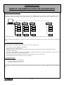
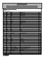
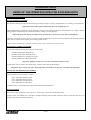
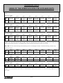
User manual
JBUS/BMS INTERFACE - ECOLEAN
Providing indoor climate comfort
MUL33E-0904 12-2009
Original manual translation
TECHNICAL DATA
USING OF THE INTERFACE KP06 FOR ECOLEAN UNITS
1.- ¿How is the net configured? (How many units can be connected, which are the combination, what is needed by the
interface?)
The purpose of this net is connecting one or more units Ecolean to a BMS system. To get this we use the interface KP06. Up to 8
units can be connected (depending sizes and characteristics), to an interface KP06. We can connect up to 15 KP06 to the net.
KP06 nº1
KP06 nº2
KP06 nº3
(. . . .)
KP06 nº15
Ctrol 1
Ctrol 1
Ctrol 1
Ctrol 1
Ctrol 2
Ctrol 2
Ctrol 2
Ctrol 2
Ctrol 3
Ctrol 3
Ctrol 3
Ctrol 3
(...)
(...)
Ctrol 8
Ctrol 8
(...)
Ctrol 8
(...)
Ctrol 8
In each Ecolean unit, is necessary to install a BUS adapter to convert the control (TTL) system in a signal RS-485.
We can connect in the net different controllers (as Climatic, Ecolean), but in a KP06 we can connect only controllers of the same
type.
2. - ¿What can be controlled by this net?
With this system, we can manage the following options in each of Ecolean units:
-
Select between OFF/STAND-BY/COOL/HEAT.
Modify the cooling / heating setpoint
Read the limitations in the unit, as the functioning of the heat pump, the maximum setpoint, and minimum setpoint. .
Read all the alarm status.
Read inlet water temperature , outlet water temperature, condensing temperature and outdoor temperature ( this last one only
if the unit is fitted with the dynamic setpoint option)
Read inlet signals status (pressostats, water flow switch, thermal relays motor protections).
Read the outlet signal status (compressor, fan, water pump ...).
3. - Fitting instructions.
It is necessary to include in every installation:
One Bus Adapter by each of the units
One KP06 at least by every 8 units
Bus Adapter will be delivered installed inside the Ecolean unit (electrical board), with the power supply taken from the general
power supply of the unit, and the control connection made. KP06 is delivered loose, for later installation in the most adequate
place.
1/13
TECHNICAL DATA
USING OF THE INTERFACE KP06 FOR ECOLEAN UNITS
4. - Connections
This sample could be the Standard connection of a KP06 net with a BMS system with a RS485 connection. It is also possible to
connect with a BMS net or a computer provided with a RS232 connection, but in this case there can be only one KP06 and the
connection cannot be longer than 15 meters (see KP06 details for further details)
Connections between KP06
KP06 nº1
KP06 nº2
(.....)
KP06 nº15
RS 485
KP06 configuration
-
-
Connection between the BMS system and the KP06 must be done
according the figure besides, taking into account the following
indications :
- The wiring has to be done according local normatives.
- Every KP06 have to be supplied with 230 Vac/50 Hz + PE
(15%). Use a cable with a 1.5 mm2 section.
- Maximum length of the RS485 net (from the BMS system to the
last) is 1.000 m.
- BMS connection is RS 485. It has to be connected to the port
RS 485 of BMS with every KP06 in parallel.
- It is advisable to use screened cable with a 0.5 mm2 for this
type of connection.
Jumpers J8 y J9 of the connected KP06 to the Ecolean units should
be connected in 1-2 position.
Switch SW2-1 of every KP06 should be in ON-OFF position, except
the last one that has to be in ON position.
Switches SW1-7 y 8 is used to configurate the transmission speed
according the following table.
Bauds
SW1-7
SW1-8
1200
ON
ON
2400
ON
OFF
4800
OFF
ON
9600
OFF
OFF
Configurate the other switches SW1 as the figure resides.
2/13
TECHNICAL DATA
USING OF THE INTERFACE KP06 FOR ECOLEAN UNITS
c) Connections between KP06 and Ecolean units.
Ecolean nº8
-
(.....)
Ecolean nº2
Ecolean nº1
In every Ecolean unit there is a Bus Adapter. In this Bus Adapter a power supply connection has been done, as well
as the control connection in the Ecolean unit.
Connection between KP06 and the Ecolean unit , has to be done as shows the figure taking into account the
following indications:
- Maximum length for the RS485 net (from the KP06 to the last ECOLEAN unit) is 2000 m.
Wiring has to be done according the local normatives.
Screened cable of 0.5 mm2 is advisable.
(for example cable model Belden 8762 with PVC isolation , cable plus metallic screen , 20 AWG, nominal capacity between cables of 89
pF, nominal capacity between a cable and the metallic screen of 161 pF)..
-
-
- Use the cables to connect + and - and the screen to connect GND.
- In each Bus Adapter of the last Ecolean, connect a 120 ohms resistance 1/4w between + and - .
Each Ecolean unit connected to a KP06 has a different address between 1 and 8 .This address is introduced in the
controller.
Climatic 200
Units EAC 0091 to EAC 0812 and EAR 0091 to 0431
Parameter H26 protocol 1
Parameter H44 family address 0
Parameter H45 device address 1.8
Climatic 400
Units EAC 1003 to EAC 1303 and EAR 0472 to EAR 1303
Parameter H48 protocol 1
Parameter H65 family address 0
Parameter H66 device address 1.8.
It is necessary configurate the KP06 to the RS485 net ( jumpers J14 and J16 in 1-2 position)
3/13
TECHNICAL DATA
USING OF THE INTERFACE KP06 FOR ECOLEAN UNITS
5.-Parameters
5. a Climatic 200
This controller is installed in EAC 0091 to EAC 0812 and EAR 0091 to 0431. This controller has the following map of standard
parameters.
/CHART 1/
/Logical parameters/
/Analogical parameters/
00H
2049
01H
2050
02H
16468
80H
2052
81H
2053
82H
2054
83H
2055
84H
2079
85H
16415
86H
16416
87H
16417
88H
16418
89H
16419
8AH
16420
8BH
16421
8CH
16422
8DH
16483
8EH
16404
8FH
16469
90H
16492
91H
16493
92H
16494
93H
16495
94H
16496
95H
16497
96H
18433
M/Pa_G01
M/Pa_G02
M/MachineStatus
Pa_H01
Pa_H02
Pa_H03
Pa_H04
Pa_H28
ST1_MSB
ST1_LSB
ST2_MSB
ST2_LSB
ST3_MSB
ST3_LSB
ST4_MSB
ST4_LSB
Ana_Output
Digit_Input
Digit_Output
Alarm_Auto_1
Alarm_Auto_2
Alarm_Auto_3
Alarm_Manu_1
Alarm_Manu_2
Alarm_Manu_3
Version
G01-Cooling setpoint
G02-Heating setpoint
Machine_Status
H01-Max setpoint in heating
H02-Min setpoint in heating
H03-Max setpoint in cooling
H04-Min setpoint in cooling
H28-HeatPump selecction
Inlet Temp : MSB
Inlet Temp : LSB
Oulet Temp : MSB
Outlet Temp : LSB
Piping : MSB
Piping : LSB
Outdoor temp : MSB
Outdoor temp : LSB
Analog Output
Digit_Input
Digital Output
Alarm_Auto_1
Alarm_Auto_2
Alarm_Auto_3
Alarm_Manu_1
Alarm_Manu_2
Alarm_Manu_3
VERSION
L/E
L/E
L/E
L
L
L
L
L
L
L
L
L
L
L
L
L
L
L
L
L
L
L
L
L
L
L
5.b Detailed information about CLIMATIC 200 parameters
00H, 01H parameters (readable and writable)
This parameter defines the setpoint which the unit will function with , in cooling mode ( parameter 00 H ) or heating mode (
01H) .
¡Important : The value of the desired temperature has to be multiplied by 10!
Introduced values for this parameter have to be within the range between minimum setpoint ( Parameter 82 H cooling / 80 H
heating ) and the maximum setpoint ( Parameter 83 H cooling / 81 H heating ) .
¡Important: if the unit Works out of this range of temperatures , unit can work suffering critical damages !
If the unit is cooling only , there is no sense in using 01H parameter . This possibility can be restrained with the parameter 84 H
, which shows with the value 1 if the unit is heat pump version .
Example : H00=110 and H01=430 shows the cooling setpoint 11.0ºC and the heating setpoint 43.0ºC
4/13
TECHNICAL DATA
USING OF THE INTERFACE KP06 FOR ECOLEAN UNITS
02H parameter (readable and writable)
This parameter defines the functioning of the unit according the following :
Parameter 02H=00H ∧ Stopped unit
Parameter 02H=04H ∧ Stand- By mode
Parameter 02H=05H ∧ Cooling only mode
Parameter 02H=06H ∧ Heating pump mode
¡Important. If values different from 0 are used, they may appear wrong values!
To know if the unit can work as a heat pump , parameter 84 H has to be read.
¡Important : if in a cooling only unit , heat pump mode is demanded , unit can work suffering critical damages!
80H, 81H, 82H, 83H parameters (only readable)
Limits of cooling setpoint and heating setpoint:
80H ∧ Maximum heating setpoint
81H ∧ Minimum heating setpoint
82H ∧ Maximum cooling setpoint
83H ∧ Minimum cooling setpoint
Use these values to establish the limits values for the parameters 00H y 01H.
84H (only readable)
Shows a 0 value if the unit is cooling only , and a 1 value if the unit is heat pump .
Use these value to establish if it is posible to modif. The heating setpoint ( H01 parameter ) and it is more important to know if it
can be switched in heat pump mode ( H02 parameter)
85H, 86H, 87H, 88H, 89H, 8AH, 8BH, 8CH parameters (only readable)
In this parameters we can read the values measured by different temperature sensors of the unit.
85H ∧ Water inlet temperature (MSB)
86H ∧ Water inlet temperature (LSB)
87H ∧ Water outlet temperature (MSB)
88H ∧ Water outlet temperature (LSB)
89H ∧ Refrigerant piping temperature (MSB)
8AH ∧ Refrigerant piping temperature (LSB)
8BH ∧ Outdoor temperature (MSB)
8CH ∧ Outdoor temperature (LSB)
Nota: The outdoor temperature will only show the correct values if the outdoor temperature sensor is included. (dynamic
setpoint kit )
To calculate the value , we have to take into account the following value:
ºC·10= MSB·256 + LSB
Example : in 85H we can read value 1 and in 86H value 172. This means 1 * 256 + 172=428. The water indoor temperature
sensor is showing a value of 42.8ºC.
5/13
TECHNICAL DATA
USING OF THE INTERFACE KP06 FOR ECOLEAN UNITS
8DH, 8EH, 8FH Parameters (only readable)
In these parameters we can read the status of the different devices of the unit.
8DH ∧ Analogical outputs (% fan speed)
8EH ∧ Digital inputs ( pressostats, protections, remote on/off , remote cooling /heating )
8FH ∧ Digital outputs (compressor , water pump, 4 way valve , antifreeze heater , alarm relay)
The correspondance with the different devices is as following :
In 8DH parameter fan speed ( in %) is shown .
0: fan stopped
100: maximum fan speed,
Intermediate values: fan in regulation
In FP2 version , this parameter only take values 0 and 10
Parameter 8EH shows the different digital inputs according the models as shown in the table below. ( 1 means closed contact
and 0 means open contact) .
EAC 0091 to 0431
Bit 7
Low pressure
switch
EAR 0091 to 0431
Bit 7
Low pressure
switch
EAC 0472 a 0812
Bit 7
Low pressure
switch
Bit 6
Bit 5
Bit 4
Bit 3
Bit 2
Bit 1
Bit 0
High
pressure
switch
Remote
ON/OFF
Compressor
protection
Flor switch
Not used
Not used
Not used
Bit 6
Bit 5
Bit 4
Bit 3
Bit 2
Bit 1
Bit 0
High
pressure
switch
Remote
ON/OFF
Compressor
protection
Flow switch
Not used
Not used
Remote
cooling
/heating
Bit 6
Bit 5
Bit 4
Bit 3
Bit 2
Bit 1
Bit 0
High
pressure
switch
Remote
ON/OFF
Compressor
1 protection
Flow switch
Not used
Not used
Compressor
protection 2
Example : in one unit EAC 0431 the value of 208 ( 1101 0000 in binary system) shows that the compressor protection , the high
pressure switch , and the low pressure switch are closed and that the remote ON/OFF plus the flow switch are opened.
With 8FH parameter we can see the functioning of the different components according models as shown in the following
table. ( 1 means functioning , 0 means stop, except the alarm relay that shows 1 when stopped or absence of alarm and shows 1
when the unit is functioning or there is an alarm)
EAC 0091 to 0431
Bit 7
Not used
EAR 0091 to 0431
Bit 7
Not used
EAC 0472 to 0812
Bit 7
Not used
Bit 6
Bit 5
Bit 4
Bit 3
Bit 2
Bit 1
Bit 0
Not used
Not used
Alarm relay
Antifreeze
heater
Not used
Water pump
Compressor
Bit 6
Bit 5
Bit 4
Bit 3
Bit 2
Bit 1
Bit 0
Not used
Not used
Alarm relay
Antifreeze
heater
4 way valve
Water pump
Compressor
Bit 6
Bit 5
Bit 4
Bit 3
Bit 2
Bit 1
Bit 0
Not used
Not used
Alarm relay
Antifreeze
heater
Compressor
2
Water pump
Compressor
1
Example : in a EAC 0431 unit , the value of 19 ( 0001 00 11 in binary system) shows that the compressor and the pump are
working , there is not alarm and the antifreeze heater is in off position.
6/13
TECHNICAL DATA
USING OF THE INTERFACE KP06 FOR ECOLEAN UNITS
90H, 91H, 92H, 93H, 94H, 95H parameters (only readable)
In these parameters the presence of an alarm is shown, and if it necessary , it can be restarted. 90H, 91H and 92H parameters,
show the alarm status ,and 93H, 94H and 95H show the necessity of restarting .
Alarm 90H restart 93H
Bit 7
Bit 6
E11
E43
Alarm 91H restart 94H
Bit 7
Bit 6
E46
E42
Alarm 92H restart 95H
Bit 7
Bit 6
Not used
Not used
Bit 5
Bit 4
Bit 3
Bit 2
Bit 1
Bit 0
E05
E04
E41
E02
E01
E00
Bit 5
Bit 4
Bit 3
Bit 2
Bit 1
Bit 0
E07
E06
E40
E45
E44
E12
Bit 5
Bit 4
Bit 3
Bit 2
Bit 1
Bit 0
Not used
Not used
Not used
Not used
E13
E03
The meaning of these different alarm codes is the following :
•
•
•
•
•
•
•
•
•
E00 ∧ remote ON/OFF
E01 ∧ High pressure
E02 ∧ Low pressure
E03 ∧ Compressor overload relay
E04 ∧ Fan overload relay
E05 ∧ Antifreeze
E06 ∧ Error in outlet water sensor
E07 ∧ Error in refrigerant piping sensor
E11 ∧ Piping high temperature
•
•
•
•
•
•
•
•
E12 ∧ Piping low temperature
E40 ∧ Error in inlet water sensor
E41 ∧ Error in flow switch sensor
E42 ∧ Error in outdoor temperature sensor
E43 ∧ External antifreeze
E44 ∧ Unit without charge
E45 ∧ Configuration error
E46 ∧ High inlet water temperature
Some of these alarms may be not activated in your unit, or have slightly different meanings. In the unit manual you will see the
meaning of every of these alarms.
Example : if a high pressure alarm appears , 90H and 93H values will take then value 2 ( 0000 0000 in binary system) , when
the cause of the alarm is eliminated , ( restarting of the pressostat) , in 90H we will have then value 0 ( 0000 0000 in binary
system ) , but in 93H the value won´t change until we restart the alarm in the controller ( pressing reset button) .
96H parameter (readable only )
This parameter shows the current version of the control software.
7/13
TECHNICAL DATA
USING OF THE INTERFACE KP06 FOR ECOLEAN UNITS
5.c Standard Climatic 400 Chart
/CHART 1/
/Logical parameters/
80H
81H
82H
83H
84H
85H
86H
87H
88H
89H
8AH
8BH
8CH
8DH
8EH
8FH
90H
91H
92H
93H
94H
95H
96H
97H
98H
99H
8193
8194
8195
8196
8197
8198
8199
8200
8201
8202
8203
8204
8205
8206
8207
8208
10241
10242
10243
10244
10245
10246
10247
10248
10249
10250
I/ID1
I/ID2
I/ID3
I/ID4
I/ID5
I/ID6
I/ID7
I/ID8
I/ID9
I/ID10
I/ID11
I/ID12
I/ID13
I/ID14
I/ID15
I/IDST4
RL1
RL2
RL3
RL4
RL5
RL6
RL7
RL8
RL9
RL10
Digital input I/ID1:
Digital input I/ID2:
Digital input I/ID3:
Digital input I/ID4:
Digital input I/ID5:
Digital input I/ID6:
Digital input I/ID7:
Digital input I/ID8:
Digital input I/ID9:
Digital input I/ID10:
Digital input I/ID11:
Digital input I/ID12:
Digital input I/ID13:
Digital input I/ID14:
Digital input I/ID15:
Digital input ST4:
Relay1 Relay2 Relay3 Relay4 Relay5 Relay6 Relay7 Relay8 Relay9 Relay10 -
L
L
L
L
L
L
L
L
L
L
L
L
L
L
L
L
L
L
L
L
L
L
L
L
L
L
M/Pa_G01
M/Pa_G02
M/MachineStatus
Pa_H01
Pa_H02
Pa_H03
Pa_H04
Pa_H10
I/ST1
I/ST2
I/ST3
I/ST4
I/ST6
Hour_funct,[1]MSB
Hour_funct,[1]LSB
Hour_funct,[2]MSB
Hour_funct,[2]LSB
Hour_funct,[3]MSB
Hour_funct,[3]LSB
Hour_funct,[4]MSB
Hour_funct,[4]LSB
Hour_funct,[PUMP]MSB
Hour_funct,[PUMP]LSB
Ana_Output_1
Ana_Output_2
Digit_Input_MSB
Digit_Input_LSB
Digit_Output_MSB
G01-Cooling setpoint
G02-Heating setpoint
Machine_Status
H01-Max setpoint in heating
H02-Min setpoint in heating
H03-Max setpoint in cooling
H04-Min setpoint in cooling
H10-HeatPump selecction
Inlet temp
Outlet Temp
Piping circuit 1
Outdoor temp
Piping circuit 2
Hours funct. Compresseur 1 x 256 h
Hours funct. Compresseur 1 x 1h
Hours funct. Compresseur 2 x 256 h
Hours funct. Compresseur 2 x 1h
Hours funct. Compresseur 3 x 256 h
Hours funct. Compresseur 3 x 1h
Hours funct. Compresseur 4 x 256 h
Hours funct. Compresseur 4 x 1h
Hours funct. Pump x 256 h
Hours funct. Pump x 1h
Analog Output 1
Analog Output 2
Digit_Input
Digit_Input
Digital Output
L/E
L/E
L/E
L
L
L
L
L
L
L
L
L
L
L
L
L
L
L
L
L
L
L
L
L
L
L
L
L
/Analogic parameters/
00H
01H
02H
80H
81H
82H
83H
84H
85H
86H
87H
88H
89H
8AH
8BH
8CH
8DH
8EH
8FH
90H
91H
92H
93H
94H
95H
96H
97H
98H
2049
2050
16495
2051
2052
2053
2054
2060
4097
4098
4099
4100
4102
16497
16498
16499
16500
16501
16502
16503
16504
16505
16506
14337
14338
16473
16474
16731
8/13
TECHNICAL DATA
USING OF THE INTERFACE KP06 FOR ECOLEAN UNITS
99H
9AH
9BH
9CH
9DH
9EH
9FH
A0H
A1H
A2H
16732
16879
16880
16881
16882
16883
16884
16885
16886
18433
Digit_Output_LSB
Alarm_Auto_1
Alarm_Auto_2
Alarm_Auto_3
Alarm_Auto_4
Alarm_Manu_1
Alarm_Manu_2
Alarm_Manu_3
Alarm_Manu_4
I/Ver
Digital Output
Alarm_Auto_1
Alarm_Auto_2
Alarm_Auto_3
Alarm_Auto_4
Alarm_Manu_1
Alarm_Manu_2
Alarm_Manu_3
Alarm_Manu_4
VERSION
L
L
L
L
L
L
L
L
L
L
5.d Detailed explanation of the CLIMATIC 400 parameters
5.d.1 /Logical parameters
In the zone of logical parameters , we can read the different status of the controller digital outlets and inlets . Correspondence
between these inlets , depending the model of unit are the following :
EAR 0472 to 0812
80H
81H
82H
High
pressure
switch 1
Low pressure
switch 1
Fan +
compressor
protection 1
88H
89H
Defrosting
switch 2
Remote
on/off
90H
91H
92AH
4 way valve 1
Compressor
2
82H
Compressor
1
98H
99H
Not used
Not used
EAC 1003 to 1303
80H
81H
83H
84H
85H
86H
87H
Defrosting
switch 1
Flow switch
High
pressure
switch 2
Low pressure
switch 2
Fan+
compressor
protection 2
8AH
8BH
8CH
8DH
8EH
8FH
Remote
cooling /
heating
Not used
Not used
Not used
Not used
Not used
92H
94H
95H
96H
97H
4 way valve 2
Water pump
Electrical
heater
Electrical
heater
Alarm
83H
84H
85H
86H
87H
Low pressure
switch 2
Fan
protection 2
Fan
protection 1
Defrosting
pressostat 1
Flow switch
High
pressure
switch 2
89H
8AH
8BH
8CH
8DH
8EH
8FH
Defrosting
pressostat 2
Remote
ON/OFF
Remote
cooling
/heating
Compressor
protection 1
Compressor
protection 2
Compressor
protection 3
Compressor
protection 4
Not used
0H
91H
92AH
92H
94H
95H
96H
97H
Fan 1
Compressor
2
Fan 2
Water pump
Electrical
heater
Electrical
heater
Alarm
83H
84H
85H
86H
87H
Flow switch
High
pressure
switch
Low pressure
switch 2
Fan
+compressor
protection
High
pressure
switch
Low pressure
switch 1
88H
Compressor
1
98H
99H
Compressor
3
Compressor
4
EAR 1003 to 1303
80H
High
pressure
switch 1
81H
Low pressure
switch 1
82H
Fan+
compressor
protection 1
Defrosting
pressostat 1
88H
89H
8AH
8BH
8CH
8DH
8EH
8FH
Defrosting
switch 2
Remote
ON/OFF
Remote
cooling/
heating
Compressor
protection 1
Compressor
protection 2
Compressor
protection 3
Compressor
protection 4
Not used
90H
91H
92AH
92H
94H
95H
96H
97H
Compressor
1
4 way valve 1
Compressor
2
4 way valve 2
Water pump
Electrical
heater
Electrical
heater
Alarm
98H
Compressor
3
99H
Compressor
4
9/13
TECHNICAL DATA
USING OF THE INTERFACE KP06 FOR ECOLEAN UNITS
5.d.2 /Analogical parameters/
00H, 01H (readable and writable)
This parameter defines the setpoint which the unit will function with in cooling ( 00H parameter) or in heating ( 01H parameter)
¡Important: Value of the required temperature has to be multiplied by 10!
Values included in this parameter must be within the range from the minimum setpoint ( 82H parameter for cooling / 80H for
heating) and the maximum setpoint ( Parameter 83H for cooling / 81 H for heating) .
¡Important: if the unit Works out of this range of temperatures, the unit may work with critical damages!
If the unit is a cooling only unit , there is not sense in using 01H parameter. We can limit this possibility with the 84 H parameter
which with the value 1 shows that the unit is heating pump version .
Example: H00=110 and H01=430 shows cooling setpoint 11.0ºC and heating setpoint 43.0ºC
02H parameter (readable and writable)
This parameter defines the function of the unit as following :
Parameter 02H=00H ∧ Stopped unit
Parameter 02H=80H ∧ Stand-By mode
Parameter 02H=81H ∧ Cooling only mode
Parameter 02H=82H ∧ Heat pump mode
¡Important: If different values are used , the result obtained maybe wrong!
To know if the unit can work in heat pump mode , read the value of the 84 H parameter.
¡Important: If in a cooling only unit , heat pump mode is demanded , the unit may work with critical damages!
80H, 81H, 82H, 83H parameters(only readable)
Cooling and heating setpoint limits, in detail :
80H ∧ Maximum heating setpoint
81H ∧ Minimum heating setpoint
82H ∧ Maximum cooling setpoint
83H ∧ Minimum cooling setpoint
Use these values to establish the limit values of the parameters 00 H and 01 H.
84H (only readable)
Shows with a value 0 if the unit is cooling only or with a value 1 if the unit is heat pump mode.
Using this value can establish if it is possible to modify the heating setpoint (H01 parameter) and more important also if we can
change to heat pump mode (H02 parameter)
10/13
TECHNICAL DATA
USING OF THE INTERFACE KP06 FOR ECOLEAN UNITS
85H, 86H, 87H, 88H, 89H parameters ( only readable)
In these parameters we can read the values measured by the temperature sensors in the unit. The values shown are ºC x 10.
85H ∧ Outlet water temperature
86H ∧ Outlet water temperature
87H ∧ Refrigerant piping temperature 1
88H ∧ Outdoor temperature
89H ∧ Outdoor temperature circuit 2
Note: Outdoor temperature will only show correct values if the unit is fitted with the outdoor temperature sensor (dynamic
setpoint kit)
Example: in 85H we will read the value 428, so the inlet water sensor is showing the value 42.8ºC.
8AH, 8BH, 8CH, 8DH, 8EH, 8FH, 90H, 91H, 92H, 93H parameters (only readable)
In these parameters we can read the hours of functioning of different components, in detail:
8AH ∧ Hours of functioning of compressor 1 (MSB)
8BH ∧ Hours of functioning of compressor 1 (LSB)
8CH ∧ Hours of functioning of compressor 2 (MSB)
8DH ∧ Hours of functioning of compressor 2 (LSB)
8EH ∧ Hours of functioning of compressor 3 (MSB)
8FH ∧ Hours of functioning of compressor 3 (LSB)
90H ∧ Hours of functioning of compressor 4 (MSB)
91H ∧ Hours of functioning of compressor 4 (LSB)
92H ∧ Hours of functioning of water pump (MSB)
93H ∧ Hours of functioning of water pump (LSB)
To calculate the value, the following formula has to be taken into account:
HR= MSB·256 + LSB
Example: in 8AH we can read the value 2 and in 8 BH a value of 48. This means 2 * 256 + 48=560. This shows that
compressor 1 has worked 560 hours.
94H, 95H, 95H, 96H, 97H, 98H, 99H parameters (only readable)
In these parameters we can read the status of the different devices of the unit:
94H, 95H ∧ Analogical outputs (% fan speed)
96H, 97H ∧ Digital inputs (pressostats, protections, remote on/ off, remote cooling/ heating)
98H, 99H ∧ Digital outputs (compressor, water pump, 4 way valve, antifreeze heater, alarm relay)
Correspondence with the different devices is the following:
94H and 95H parameters show the speed (in %) of fans 1 and 2 :
0: fan stopped
100: maximum fan speed
Intermediate values: fan in regulation
This value is valid for:
- EAR 0472 to 0812 standard and FP1.
- EAR 1003 to 1303 but only taking 0 and 100 values.
11/13
TECHNICAL DATA
USING OF THE INTERFACE KP06 FOR ECOLEAN UNITS
96H y 97H parameters show the different digital inlets, according the models as following (1 means closed contact and 0 open
contact)
EAR 0472 to 0812
Bit 7
Bit 6
Bit 5
Bit 4
Bit 3
Bit 2
Bit 1
Low pressure
switch 1
Fan + comp
protection 1
Not used
Not used
Bit 0
96H
Not used
Not used
High
pressure
switch 1
97H
Defrosting
switch 2
Fan +
compressor 2
protection
Remote
ON/OFF
Not used
Low pressure
switch 2
Flow switch
Defrosting
switch
Bit 6
Bit 5
Bit 4
Bit 3
Bit 2
Bit 1
Bit 0
Low pressure
switch 1
Fan
protection 1
Not used
Compressor
protection 2
Not used
EAC 1003 to 1303
Bit 7
Remote
cooling /
heating
High
pressure
switch 2
96H
Compressor
protection 4
Compressor
protection 3
High
pressure
switch 1
97H
Not used
Fan
protection 2
Remote
on/off
Compressor
protection 1
Low pressure
switch 2
Flow switch
Not used
High
pressure
switch 2
Bit 6
Bit 5
Bit 4
Bit 3
Bit 2
Bit 1
Bit 0
Low pressure
switch 1
Fan
protection 1
Not used
Compressor
protection 1
Not used
Compressor
protection 2
Low pressure
switch 2
Flow switch
Defrost swicth
1
High
pressure
switch 2
EAR 1003 to 1303
Bit 7
96H
Compressor
protection 4
Compressor
protection 3
High
pressure
switch 1
97H
Defrosting
pressostat 2
Fan
protection 2
Remote
ON/OFF
Example : in a unit EAC 1103 the value of 96H is 208 (1111 1010 in binary) shows that the protections of the compressors 4,3
and 2 , the protection of the fan 1 , the high pressure switch 1 and the low pressure switch 1 are closed.
98H y 99H will show the functioning of the following devices, according the models (1 means functioning, 0 means stop)
EAR 0472 to 0812
Bit 7
98H
99H
Electrical
heater
Fan 1 ( only
FP2 version)
EAC 1003 to 1303
Bit 7
98H
99H
Electrical
heater
Compressor
3
EAR 1003 to 1303
Bit 7
98H
99H
Electrical
heater
Compresor 3
Bit 6
Electrical
heater
Fan 2 ( only
FP2 version)
Bit 6
Electrical
heater
Compressor
4
Bit 6
Electrical
heater
Compresor 4
Bit 5
Bit 4
Bit 3
Bit 2
Bit 1
Bit 0
Water pump
4 way valve 2
Compressor
2
4 way valve 1
Compressor
1
Alarm
Not used
Not used
Not used
Not used
Not used
Not used
Bit 5
Bit 4
Bit 3
Bit 2
Bit 1
Bit 0
Alarm
Not used
Water pump
Fan 2
Compresso 2
Fan 1
Compressor
1
Not used
Not used
Not used
Not used
Not used
Bit 5
Bit 4
Water pump
4 way valve 2
N/U
N/U
Bit 3
Compressor
2
N/U
Bit 2
4 way valve 1
N/U
Bit 1
Compressor
1
N/U
Bit 0
Alarm
N/U
Example : in one unit EAC 0472 the value of 34 (0010 0010 in binary) show that there are only functioning compressor 1 and
water pump .
12/13
TECHNICAL DATA
USING OF THE INTERFACE KP06 FOR ECOLEAN UNITS
9AH, 9BH, 9CH, 9DH, 9EH, 9FH, A0H, A1H parameters (only readable)
In these parameters it is shown the presence of an alarm , and if it is neccessary the restarting. 90H, 91H and 92H parameters
shown the status of the alarm and 93H, 94H and 95H the necessity of restarting .
Alarm 9AH restart 9EH
Bit 7
Bit 6
E07
E06
Alarm 9BH restart 9FH
Bit 7
Bit 6
E23
E22
Alarm 9CH restart A0H
Bit 7
Bit 6
E33
E32
Alarm 9DH restart A1H
Bit 7
Bit 6
E46
E45
Bit 5
Bit 4
Bit 3
Bit 2
Bit 1
Bit 0
E05
E04
E03
E02
E01
E00
Bit 5
Bit 4
Bit 3
Bit 2
Bit 1
Bit 0
E21
E19
E13
E12
E11
E09
Bit 5
Bit 4
Bit 3
Bit 2
Bit 1
Bit 0
E31
E29
E27
E26
E25
E24
Bit 5
Bit 4
Bit 3
Bit 2
Bit 1
Bit 0
E44
E43
E42
E41
E40
E39
The meaning of the alarms is the following:
•
•
•
•
•
•
•
•
•
•
•
•
•
•
•
•
E00 ∧ remote ON/ OFF
E01 ∧ High pressure circuit 1
E02 ∧ Low pressure circuit 1
E03 ∧ Compresso overload relay 1
E04 ∧ Fan overload relay 1
E05 ∧ Antifreeze circuit 1
E06 ∧ Error water outlet sensor
E07 ∧ Error refrigerant piping sensor circuit 1
E09 ∧ High pressure compressor 1
E11 ∧ High pressure piping circuit 1
E12 ∧ Low pressure piping circuit 1
E13 ∧ Overload protection compressor 2
E19 ∧ High pressure compressor 2
E21 ∧ High pressure circuit 2
E22 ∧ Low pressure circuit 2
E23 ∧ Overload protection compressor3
•
•
•
•
•
•
•
•
•
•
•
•
•
•
•
•
E24 ∧ Fan overload protection 2
E25 ∧ Antifreeze protection 2
E26 ∧ Error sensor ST5
E27 ∧ Error refrigerant piping sensor 2
E29 ∧ High pressure compressor 3
E31 ∧ High piping temperature circuit 2
E32 ∧ Low piping temperature circuit 2
E33 ∧ Overload protection compressor 4
E39 ∧ High pressure compressor 4
E40 ∧ Error water inlet sensor
E41 ∧ Error flow switch sensor
E42 ∧ Error outdoor temperature sensor
E43 ∧ External antifreeze
E44 ∧ Unit without charge
E45 ∧ Error in configuration
E46 ∧ High inlet water temperature
Some of these units may be not available in the unit, or have slightly different meanings. See the manual of the unit to know the
detailed meaning of each alarm
Example : if appear one alarm by high pressure , the parameters 9AH and 9EH will take value 2 2 (0000 0010 in binary),
when the cause of the alarm is settled ( pressostat restarted) , parameter 9AH will show the value 0 (0000 0000 in binary) but
in the parameter 9EH nothing will change until we do not reset the alarm in the controller ( pressing the reset button) .
A2H parameter (only readable)
This parameter shows the current version of the software control.
13/13
www.lennoxeurope.com
BELGIUM, LUXEMBOURG
www.lennoxbelgium.com
PORTUGAL
www.lennoxportugal.com
Due to Lennox’s ongoing commitment to quality,
the Specifications, Ratings and Dimensions are
subject to change without notice and without
incurring liability.
CZECH REPUBLIC
www.lennox.cz
RUSSIA
www.lennoxrussia.com
Improper
installation,
adjustment,
alteration,
service or maintenance can cause property
damage or personal injury.
Installation and service must be performed by a
FRANCE
www.lennoxfrance.com
SLOVAKIA
www.lennoxdistribution.com
GERMANY
www.lennoxdeutschland.com
SPAIN
www.lennoxspain.com
GREAT BRITAIN
www.lennoxuk.com
UKRAINE
www.lennoxrussia.com
NETHERLANDS
www.lennoxnederland.com
OTHER COUNTRIES
www.lennoxdistribution.com
POLAND
www.lennoxpolska.com
MUL33E-0904 12-2009
Original manual translation
qualified installer and servicing agency.