Download TELEASTRO
Transcript
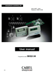
TELEASTRO
SETTING AND CONTROL OF STREET LIGHTING
USER’S MANUAL
AFEI Sistemas y Automatización, S.A.
INDICE
Description of the unit........................................................................................................................................................2
Technical characteristics......................................................................................................................................................3
Safety warnings...............................................................................................................................................5
Storage and maintenance.......................................................................................................................................5
Initial turning on .......................................................................................................................................6
Functioning keys, symbols, and leds.......................................................................................................7
Screen in Wait Mode................................................................................................................................9
SETUP Menu................................................................................................................................................10
TELEASTRO.NET system ......................................................................................................11
Coordinates.......................................................................................................................12
Time-Server..............................................................................................................................13
Force Time-Server...................................................................................................................14
CLOCK..............................................................................................................................15
Time Change.....................................................................................................................16
Intensity transformers..............................................................................................................17
Language...........................................................................................................................18
Lock keyboard..................................................................................................................19
PROGRAMMING Menu..........................................................................................................20
Weekly...............................................................................................................................25
Special Day...............................................................................................................................30
For a rank of dates....................................................................................................................32
In Relation to Easter .................................................................................................................34
Ejemplos Programación............................................................................................................36
TEST Menu...........................................................................................................................................38
Lectura Parámetros Eléctricos.................................................................................................39
Reading Analogical Measurements MA....................................................................................41
Status Digital Inputs Alarms CA.................................................................................................42
Hours Counter...................................................................................................................43
Status of the Unit...............................................................................................................45
Remote Mode....................................................................................................................46
Test Modem..............................................................................................................................47
Signal Test ...............................................................................................................................48
Peripheric Test .........................................................................................................................48
Keyboard Test...................................................................................................................49
Display Test ......................................................................................................................49
Menu ALARMS......................................................................................................................................50
SMS of Consultations and Programming...............................................................................................52
Password...................................................................................................................................................................56
Wiring............................................................................................................................................57
GPRS Modem Wiring.................................................................................................................57
Wiring Control Circuits and Intensity Transformers..................................................................58
Wiring Switchboard Door Alarm and Manual/Automatic Switch................................................59
Wiring Digital Alarm Inputs........................................................................................................60
Diagnosis of errores and breakdowns..................................................................................................61
The total or partial reproduction of this manual is not permitted, neither is its computer handling, nor transmission in any way or by any
means, whether electronic, ,mechanical, photocopying, recording or other methods, without the prior written consent of the Copyright holders.
AFEI Sistemas y Automatización, S.A.
Composition and Publication: AFEI Sistemas y Automatización, S.A.
Printing: AFEI Sistemas y Automatización, S.A.
The data contained in this manual may be subject to change without advance notification and in no respect represents a commitment on
the part of the seller.
Second edition: October 2009
-1-
DESCRIPTION OF THE UNIT
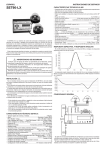
The TELEASTRO is a control and setting system for street lighting using the latest technologies, such
as Internet, GPRS communication and SMS Messaging, to provide an easy to install solution and
above all flexible and efficient performance.
CONTROLS
- Astronomic calculation by high-accuracy algorithm based on geographical coordinates in degrees and minutes.
- Automatic time setting through Internet, based on an atomic clock of reference.
- Four outlets for setting the installation with astronomical and/or time programming.
- Multiple programming choices for creating personalised calendars.
- Automatic calculation of Easter Sunday for programming movable days.
- Configuration and automatic turning on by the GPRS modem.
- Keyboard and display for test, programming and setting.
LOCAL CONTROL
- Basic programming by keyboard or automatic through the TELEASTRO.NET System.
- Viewing the status of the switchboard and alarms, through the display and the status leds.
- Automatic activation of the normal programming when a remote programming operation has finished.
REMOTE CONTROL BY SMS MESSAGING
- Reception of priority alarms.
- Remote control and remote programming of settings.
- Consultation of the status of the switchboard and the alarms, apart from monitoring and controlling them.
CONTROLLING THE INSTALLATION THROUGH THE TELEASTRO.NET SYSTEM
- Complete programming of settings and alarm orders.
- Monitoring of protections and alarms of the lighting up switchboard with control of the restart differentials.
- Supervising functioning of any flow regulator or savings system.
- Alarms and recordings of the electrical parameters in three-phase networks with and withouth neutral.
- Automatic creation of status reports of the installations.
- Supervision of installations by clients, zones or districts.
-2-
TECHNICAL CHARACTERISTICS
- Setting circuits outlets / Type.......................................................................................................4 / Relay
Contact circuit C1, C3 and C4......................................................................................................NC
Contact circuit C2 commutation.........................................................NC (connector 24 and 25)
Maximum commutation voltage...........................................................................277 VAC, 30 VDC
Maximum commutation current.......................................................................10A (VAC), 5A (VDC)
Maximum commutation power............................................................................1660 VA, 150 W
Insulation between open contacts......................................................................................750 VAC
- Digital alarm inputs CA....................................................................................................7 (Optoinsulated)
Frequency.......................................................................................................................500ms
Type of detection................................................................Opening / Closing potential-free contact
- Beat counter inputs CA...................................................................................................2 (Optoinsulated)
Frequency beat counter inputs......................................................................5ms per beat (100Hz)
- Analogical inputs MA...................................................................................3 (VL1-VL3) + 4 (MA0-MA3)
Resolution inputs .................................................................................................................10 bits
- Maximum voltage applicable (VLn - N)......................................................................................240 VAC
- Maximum voltage applicable (MAn-Com -).......................................................................±VDC, 2 VAC
- Internal Protection..........................................................................................................................by PTC
- External Protection......................................................................Omnipole cut device (230 VAC / 2 A)
- Terminals......................................................................................................................................230 VAC
- Communications ports...........................................................................RS232 + RS485 (Optoinsulated)
Transmission speed........................................................................................1200 to 38400 bauds
- Clock...............................................................................................................Accuracy ± 3s/year (25ºC)
Updating TIME-SERVER (by GPRS).........................................................................................YES
- Battery........................................................................................................3V 220mAh Lithium long play
(*) At the analogical inputs, toroidal transformers model "TRAFO-20" will be connected to measure current (xA / 1.5 VAC),
being fitted internally with an electric protection system against over-intensity.
-3-
-
-
-
Display.........................................................................................................................type reflective LCD
Leds................................................................................................................7 cylindrical indication leds
Keyboard............................................................................................................................6 silicone keys
Weight.........................................................................................................................................700g
Box..................................................................................................................................8 pitch DIN rail
Box measurements.....................................................................................140 x 118 x 71 mm
Panelled IP protection....................................................................................................................31
Non-panelled IP protection............................................................................................................30
Frontal measurements....................................................................................................140 x 45mm
Consumption at 230V~ (*)...............................................................................................................7VA
Working voltage...............................................................................................................230VAC +/- 15%
Working frequency......................................................................................................................50 – 60Hz
Working temperature................................................................................................................-20 to 75oC
Storage temperature...............................................................................................................-40 to 125oC
Air humidity (without condensation)....................................................................................................95%
Microprocessor....................................................................................................................H8 of 32 bits
Type of the programations..........................................................................................8 settings by circuit
Programming special days.................................................................................................200 days
Weekly programming.................................................................................................................YES
Programming by ranks of dates..........................................................................................50 ranks
Programming in relation to Easter Sunday.................................................................................YES
Programming SMS.......................................................................................................4 settings by circuit
Dates of time change....................................................................................................................50 años
Register eventos / Register medidas (capacity).........................................................................4 Kbytes
(*) With inputs and outputs activates, display, RS232 and RS485.
-4-
SAFETY WARNINGS
WARNING: The symbol
indicates that there is a risk to the user, so the manual shall be consulted
for information on the part indicated.
Any use of the unit in a manner other than that specified by the manufacturer could compromise the
safety of the unit and affect the protection of the user.
Handling or installation of the unit must be performed with the unit disconnected from the power supply.
WARNING: Connector 18 (NEUTRAL) and connector 14 (COM-) are internally connected in the
unit. They may be at dangerous potentials for the user. You must NEVER connect a referenced
unit to earth between any analogical input MAx and COM (-).
STORAGE AND MAINTENANCE
It is recommended that the equipment is stored in the respective packing boxes and bearing in mind
several minimum climactic conditions such as those in the technical characteristics.
Installation does not require prior building work to be carried out. All that is needed is to ensure the
appropriate drill hole or assemble the appropriate DIN rail in the distribution board where it will be
located. Also, the wiring terminals will not be accessible.
In the place where the unit is to be installed, the minimum space allocated to ventilation and to the
connection of the wires of the unit terminals must be observed.
This unit does not have a fuse, so connection of a protection fuse and anti-parasite filter at the supply
socket is shall be installed.
Leads with maximum section of 2.5mm is recommended for wiring to the unit terminals.
It is recommended to use leads with maximum section of 2.5mm and minimum of 1.5mm for wiring to the
unit connectors (Flexible leads type H07V-K are recommended).
All that is needed to clean the front casing is a damp (not wet) cloth with water and neutral soap, not with
an abrasive cleaner.
Parts to be examined by the technical service:
- Activation of relays and contactors for setting by manual drive.
- Good condition of the leads, of the riveted terminals and connectors, location of points where
abnormal arcs or over-heating have occurred and proper tightening of connectors.
- Adequate size of the setting elements and normal running of the unit.
-5-
INITIAL TURNING ON
The following is a description of the steps required to turn on the unit for the first time with connection
to the TELEASTRO.NET system (by GPRS network) or without connection.
Turning on with connection to the TELEASTRO.NET System
A.- Before installing the unit in its final location, fill in and send the Application Form for Registration
with the TELEASTRO.NET System, following the instructions in it.
B.- Check that the intensity transformers are correctly installed (see submenu «Reading Electrical
Parameters» in the «TEST Menu» chapter).
C.- Check the behaviour of the manual/automatic switch (if on changing the switch to manual, the
«hand» symbol appears on the display, it indicates that the switch is properly installed).
D.- Enter the preselection of the active energy counter (see page 40).
E.- Connect the unit to the TELEASTRO.NET System (see page 11).
F.- Once the system has transmitted registration, it will programme it automatically. The user will be
informed by an SMS message once the unit is operative.
Turning on without connection to the TELEASTRO.NET System
A.- Select the unit language (it is Spanish by default).
B.- Enter the geographical coordinates of the corresponding location.
C.- Check that the intensity transformers are correctly installed (see submenu «Reading Electrical
Parameters» in the «TEST Menu» chapter).
D.- Check the behaviour of the manual/automatic switch, as indicated in step C of the previous
paragraph.
E.- Enter the preselection of the active energy counter.
F.- Programme the turnings on and/or off of the setting circuits that we desire.
G.- Check the time and the date.
-6-
KEYS AND SYMBOL FUNCTIONING
KEYS
- Key «OK» allows access to the menus, submenus and confirming data.
- Key S or T allows increasing or decreasing values, changing options and accessing the different
screens of the display.
- The key
enables exiting from the screen or cancelling.
- Key W or X allows selecting the value to be modified and accessing the different screens.
SYMBOLS
: Indicates that we are in the submenu to view or to modify the time and date of the unit or that
we are carrying out time type setting programming.
: Indicates that we are in daytime (between sunrise and sunset) or programming a setting in
relation to sunrise.
: Indicates that we are at night (between sunset and sunrise) or programming a setting in
relation to sunset.
: Indicates that we are in the submenu to view or to modify the geographic coordinates.
: Indicates the type of programming that is programmed in the unit, as well as indicating the
circuit that contains some programming within the type of programming (Weekly, special,etc…).
: Indicates that the unit is in Manual mode.
: Indicates that there are active alarms in the unit.
MIN : Indicates that there is an alarm for minimum setting.
MAX : Indicates that there is an alarm for maximum setting.
-7-
OFF :Indicates that the setting circuit is disconnected or the next setting circuit turning off time is
disconnected or that the turning off setting is being programmed.
ON :Indicates that the setting circuit is connected or the next setting circuit turning on time is
disconnected or that the turning off setting is being programmed.
1
:Indicates that the next sunrise or sunset that is being viewed on screen is for the day in hand
and also indicates if the next setting is for the day in hand.
2
:Indicates that the next sunrise or sunset that is being viewed on screen is for tomorrow and
also indicates if the next setting is for tomorrow.
:Indicates the menu that we are in.
C1, C2, C3 y C4: Indicates that the corresponding setting circuit is programmed.
r
: Indicates that the alarm has occurred during savings hours.
m
: Indicates that the alarm has occurred during full power hours.
LEDS
- C1, C2, C3 and C4: Indicates the status of the setting circuit (led on=contact closed).
- Rx / Tx: Indicate reception and transmission of data through the communications series port.
KEYS
SYMBOLS
LEDS
LEDS
-8-
WAIT MODE SCREEN
On the «Wait mode screen» screen you will see:
- The current time and date of the unit.
- The setting circuits that are activated (C1 to C4).
On the «Wait mode screen» screen, if we press key S or T , it shows us the next Sunrise or Sunset
after the current time.
On the «Sunrise» y «Sunset» screens you will see:
- The time corresponding to the Sunrise or Sunset.
- Symbol 1 if it is Sunrise or Sunset of the current day or symbol 2 if it is Sunrise or Sunset of
tomorrow.
On the «Wait mode screen» screen, if we press key W or X , it shows us the screen of the next
setting of each circuit that is programmed. Pressing keys S or T the setting circuit is changed.
This screen will show:
- The symbol C1, C2, C3 or C4.
- The symbol ON or OFF and the time of the next circuit setting viewed on screen (maximum
current day and next).
no PROG
- If the circuit is not programmed, «no
PROG» will be seen on screen.
no
- If the circuit is programmed but there is no setting for the current day and the next, «no
MAN
MAN» will be seen on screen.
NOTE
- We exit from this screen by pressing the key
or in 15 seconds if no key is pressed.
-9-
SETUP MENU
TELE SETUP
The «TELE
SETUP» menu allows configuring and programming specific parameters of the unit:
programme coordinates, time change, lock keyboard, etc.
Pressing the «OK» key, we access the main menu. Select the «TELE
SETUP» menu with key S
TELE SETUP
or T and confirm with the «OK» key again.
The «TELE
SETUP» menu consists of a series of submenus, which we will describe below.
TELE SETUP
- 10 -
TELEASTRO.NET SYSTEM
The «TELEASTRO.NET System» submenu allows connecting or disconnecting the unit to
the TELEASTRO.NET System, set the mode of operation of the communications network
(depending on the telephone operator GPRS) and force a GPRS mode of operation NAT.
TELEASTRO.NET System Configuration:
1.- Press the «OK» key to access menus.
Enter the access password if it is required (see «Password» chapter).
TELE SETUP
2.- Select the «TELE
SETUP» menu with the key
or
and press the «OK» key.
3.- With key
or
choose the cubmenu and press the «OK» key.
4.- Through the key
or
shows cyclically the screen to connect to the computer System
SET NET
Teleastro.net «SET
NET» and set the mode of operation of the communications network GPRS
SET NAT
«SET
NAT».
5.- Press again the «OK» key if you wish to modify the indication of the choice that is displayed on the
screen at that time.
Y» or «N
N» indication of the corresponding option will flash.
The «Y
6.- Modify the indication of the option with the key
or
.
7.- Confirm with the «OK» key or press key
to cancel and to exit from the submenu.
NOTES
- You need to have a GPRS modem connected and an access to the GPRS network.
- When the unit has established the connection to the TELEASTRO.NET System (whether after a
net ACTIV
reset or by reconnection to the System) «net
ACTIV» will come up on screen for a moment.
Cnct SERVR
SERVR» will be displayed only if the
- The screen to force a GPRS connection mode NAT «Cnct
Set NA
T Y
mode of operation of the network is configured as NAT «Set
NAT
Y».
Set NET Y
Y» and we want
- If your equipment is already connected to the System Teleastro.net «Set
to disconnect; will be asked a password to access, otherwise not.
- 11 -
COORDINATES
The submenu «Coordinates» allows programming the data relating to geographic
location of the place (geographic coordinates and GMT). By manufacturing default,
the ones configured are those of Barcelona (Spain).
Programming coordinates:
1.- Press «OK» key for access to menus.
Enter the access password if required (see «Password» chapter).
TELE SETUP
2.- Select «TELE
SETUP» menu with key S or T and press the «OK» key.
SET L A-L
O» and press the «OK» key.
3.- With key S or T choose the submenu «SET
-LO
First of all, the latitude screen is shown.
4.- With key S or T , the Latitude, Longitude and GMT screen is shown cyclically.
5.- Press the «OK» key again if you wish to modify any value of the screen that is being shown at that
moment.
The values of the degrees will flash first on the Latitude or Longitude screens.
6.- With keys W or X select the value to be modified, which will flash on screen.
7.- With keys S or T respectively increase or reduce the value that is flashing.
SET OK
OK» will appear for an instant) or press the key
to cancel.
8.- Confirm with the «OK» key («SET
9.- Repeat steps 4 to 8 to modify values of other screens.
10.- Use the key
to exit from the submenu.
NOTE
- GMT will increase or decrease 15 minutes whenever key S or T is pressed.
- 12 -
TIME-SERVER
The submenu «Time-Server» allows automatically activating or deactivating the
updating of the clock through an Internet time server.
Time-Server Configuration:
1.- Press the «OK» key to access the menus.
Enter the access password if it is required (see «Password» chapter).
TELE SETUP
2.- Select the «TELE
SETUP» menu with key
or
and press the «OK» key.
SET TMS
3.- With the key
or
choose the submenu «SET
TMS».
SET TMS Y
If the option «SET
Y» is displayed on the screen, clock updating is activated or the
SET TMS N
«SET
N» option if it is not activated.
4.- Press the «OK» key if you wish to modify the option.
Y» or «N
N» of the corresponding option will flash.
The indication «Y
5.- Modify the indication of the option with key
or
.
SET OK
6.- Confirm with the key «OK» ( «SET
OK» will be displayed for a moment) or press the key
to
cancel.
7.- Use the key
to exit from the submenu.
NOTES
- This submenu will be displayed on screen if the unit is connected to the TELEASTRO.NET System
(see «TELEASTRO.NET System» submenu in this same chapter).
- If the «Time-Server» is activated, the unit will automatically update the time every 7 days.
- 13 -
FORCE TIME-SERVER
The submenu «Force Time-Server» allows automatically forcing the clock updating
through an Internet time server.
Force Time-Server updating:
1.- Press the «OK» key to access the menus.
Enter the access password if it is required (see «Password» chapter).
TELE SETUP
2.- Select the «TELE
SETUP» menu with key
or
and press the «OK» key.
InI TIME
3.- With the key
or
select the «InI
TIME» submenu.
4.- Confirm with the «OK» key to force updating the time.
Once the time has been updated, check it.
5.- Use the key
to exit from the submenu.
NOTES
- This submenu will be displayed on screen if the unit is connected to the TELEASTRO.NET System
(see «TELEASTRO.NET System» submenu in this same chapter).
OPEN TIME
- If there is connection to the time server, «OPEN
TIME», will be displayed on the screen, otherwise
NO TIME
End TIME
«NO
TIME». As soon as updating is over, «End
TIME» will come up on screen for a moment.
- 14 -
CLOCK
The menu «Clock» allows viewing and modifying the internal time and date of the
unit.
Modification time and date:
1.- Press the «OK» key to access menus.
Enter the access password if required (see «Password» chapter).
TELE SETUP
2.- Select the menu «TELE
SETUP» with key S or T and press the «OK» key.
Set CL
OCK
3.- Select the menu «Set
CLOCK
OCK» with key S or T and press the «OK» key.
Will appear on screen the current time and date of the unit, if press the W or X will appear other
screen with the year and to the day of the week.
4.- Press the «OK» key again if you wish to modify any value.
The values of the hours will flash first.
5.- With keys W or X select the value to be modified, which will flash on screen.
6.- With keys S or T respectively increase or reduce the value that is flashing.
7.- Repeat steps 5 to 6 to modify values.
SET OK
8.- Confirm with the «OK» key («SET
OK» will appear for an instant) or press the key
to cancel.
9.- Use the key
to exit from the submenu.
NOTES
- This submenu will be displayed on screen if the unit is connected «Time-Server».
- The day of the week cannot be changed because it remains fixed automatically by thedate.
- 15 -
TIME CHANGE
The submenu «Time change» allows activating or deactivating the Summer/Winter
time change.
Time change configuration:
1.- Press the key «OK» to access menus.
Enter the access password if required (see «Password» chapter).
TELE SETUP
SETUP» menu with key S or T and press the «OK» key.
2.- Select «TELE
SET TCH
3.- With key S or T choose the submenu «SET
TCH».
SET TCH Y
The option «SET
Y» is shown on screen if the Summer/Winter time change is activated
SET TCH N
and the option «SET
N» if the Summer/Winter time change is not activated.
Y» or «N
N» will flash.
4.- Press the «OK» key if you wish to modify the option. The indication «Y
5.- Modify the option indication with key S or T and confirm with the «OK» key.
Configuration time change dates:
SEt CH
1.- Press the Key W or X in the submenú «SEt
CH».
2.- With keys S or T select the year of the time change and press the «OK» key.
The day of the first time change will flash first.
3.- With keys W or X select in rotation the day of the first time change, the month of the first time
dIA1
change (screen «dIA1
dIA1»), the day of the second time change or the month of the second time
dIA2
change (screen «dIA2
dIA2») to be modified, which will flash on screen.
4.- With keys S or T respectively increase or decrease the value that is flashing.
SET OK
5.- Confirm with the «OK» key («SET
OK» will appear for an instant) or press the key
to cancel.
6.- Repeat steps 2 to 5 if you wish to modify more time change dates.
7.- Use the key
to exit from the submenu .
- 16 -
INTENSITY TRANSFORMERS
The submenu «Intensity Transformers» allows configuring the unit so that the
analogical inputs MA1, MA2 and MA3 measure current by suitable transformers
for reading the electrical parameters. If it is configured as NO, the inputs will
measure continuous currents. By default it is configured for connecting Intensity
Transformers.
Intensity transformer configuration:
1.- Press the «OK» key to access the menus.
Enter the access password if it is required (see «Password» chapter).
TELE SETUP
SETUP» menu with key
or
and press the «OK» key.
2.- Select the «TELE
SET TRAFO
3.- With the key
or
select the submenu «SET
TRAFO» and press the «OK» key.
Y» will flash on screen if the unit uses the analogical inputs for measuring
The indication «Y
N» if the analogical inputs are configured for measuring continuous
current or the indication «N
currents.
4.- Modify the indication with the key
or
if you wish.
SET OK
5.- Confirm with the «OK» key («SET
OK» will appear for a moment) or press the key
to cancel.
Y » has been selected, another screen will come up, in which you should enter the
If indication «Y
scale factor (in Amps). The value of the scale factor will flash.
6.- With key
or
respectively increase or decrease the scale factor value. It will increase or
decrease by 5 units every time the key
or
is pressed.
SET OK
7.- Confirm with the «OK» key («SET
OK» will appear for a moment) or press key
to cancel.
8.- Use key
to exit from the menu.
NOTE
- If it is configured as YES it will only read the input «MA0» as analogical input.
- 17 -
LANGUAGE
The submenu «Language» allows viewing and modifying the language of the unit
menus. By manufacturing default, Spanish is configured.
Language configuration:
1.- Press the «OK» key to access menus.
Enter the access password if required (see «Password» chapter).
TELE SETUP
2.- Select the menu «TELE
SETUP» with key S or T and press the «OK» key.
L ANG
3.- With key S or T choose the submenu «L
ANG».
L ANG SP
The option «L
SP» will appear on screen if the current language is Spanish, the option
L ANG ENG
L ANG FR
«L
ENG» if the language is English and the option «L
FR» if the language is
French.
4.- Press the «OK» key is you wish to modify the option.
SP
ENG
FR
The indication «SP
SP», «ENG
ENG» or «FR
FR» of the corresponding option will flash.
5.- Modify the indication of the option with key S or T
SET OK
6.- Confirm with the «OK» key («SET
OK» will appear for an instant) or press the key
to cancel.
7.- Use the key
to exit from the submenu.
NOTE
- If you press the key
on the «Wait Mode Screen» screen for more than 5 seconds, you will
access this submenu directly.
- 18 -
LOCK KEYBOARD
The submenu «Lock Keyboard» enables you to lock or unlock access to the
menu by the keyboard of the unit in order to protect it from misuse. By manufacturing
default it is unlocked.
Keyboard configuration:
1.- Press the «OK» key to access menus.
Enter the access password if required (see «Password» chapter).
TELE SETUP
2.- Select the menu «TELE
SETUP» with key S or T and press the «OK» key.
PAd
3.- With key S or T choose the submenu «P
Ad».
PAD UNLCK
PAD
The option «P
UNLCK» will be shown on screen if the unit is unlocked or the option «P
LOCK
LOCK» if it is locked.
4.- Press the «OK» key and X simultaneously if you wish to modify the option.
LOCK
UNLCK
The indication «LOCK
LOCK» or «UNLCK
UNLCK» of the corresponding option will flash.
5.- Modify the option indication with key S or T
SET OK
6.- Confirm with the «OK» key («SET
OK» will appear for an instant) or press the key
to cancel.
7.- Use the key
to exit from the submenu.
NOTES
- If the keyboard is unlocked or the password is «0000» access to the menu by the keyboard of the
unit.
- With the keyboard locked, no option will be able to be viewed or modified.
- 19 -
PROGRAMMING MENU
The menu «Programming» allows programming turning on and/or turning off the setting circuits on the
basis of the type of calendar and programming options selected. This menu will only be displayed if the
unit is not connected to the TELEASTRO.NET System, if you try to access it while connected to this
no VALID
system, «no
VALID» will come up on screen for a moment.
By pressing the «OK» key, access the main menu. Select the menu «TELE
PROG» with key S or
TELE PROG
T , and confirm with the «OK» key again.
DESCRIPTION SETTING CIRCUITS
PROG
The menu «PROG
PROG» allows you to independently carry out the programming of turning on and/or
turning off the setting circuits C1, C2, C3 and C4 which are described below:
- Setting circuit «C1» is the Astronomic circuit and is used for control of the main circuit of street
lighting.
- Setting circuit «C2» is the one used for connection of the Energy Saving System that is used
(regulator-stabiliser, ballast, half turn-off, etc) It can also function as a special setting circuit.
- Setting circuit «C3» and «C4» is referred to as Special, and tends to be used to connect another
independent circuit (for example: fountains, monuments, advertising panels, lighting of buildings,
etc.).
- 20 -
TYPES OF PROGRAMMING CALENDAR
In the programming menu there are different types of programming calendar for a setting circuit, as
described below:
Pro
Pro
Pro
Pro
Pro
Pro
Pro
Pro
MON
TUE
WEDN
THUR
FRID
SAT
SUN
ALL
Weekly programming for every Monday.
Weekly programming for every Tuesday.
Weekly programming for every Wednesday.
Weekly programming for every Thursday.
Weekly programming for every Friday.
Weekly programming for every Saturday.
Weekly programming for every Sunday.
Weekly programming, copies the programming entered for each of the days of the
week.
Pro SDAYS Special Day or of a day In Relation to Easter Sunday or a Rank of Dates for
every year, programming.
Pro EDAYS Special Day or of a day In Relation to Easter Sunday or a Rank of Dates for a
specific year, programming.
The priorities of the setting programmed for the current day vary according to the type of calendar that
has been programmed. The order of priorities is:
1.2.3.4.5.-
Pro ED
AYS
EDA
YS: a Special Day or In Relation to Easter Sunday with specified year.
Pro ED
AYS
EDA
YS: a Rank of Dates with specified year.
Pro SD
AYS
SDA
YS: a Special Day or In Relation to Easter Sunday for every year.
Pro SD
AYS
SDA
YS: a Rank of Dates for every year.
In the event of there not being any of the above programmes, it will execute the Weekly
Programming corresponding to the day of the week of the day in hand.
- 21 -
SETTING CIRCUIT PROGRAMMING OPTIONS
In a setting circuit, the following programming options have to be programmed, as described below.
Number of setting
OPE n
Programming type
We indicate the number of the setting to be programmed
(maximum 8).
Hour programming.
Programming in relation to Sunrise.
Programming in relation to Sunset.
Hour / Minute
Setting
noPr
Not programmed.
HH:MM
Hour and minutes for the time programming.
+/- MM
Minutes of difference for Programming in relation to Sunrise
or to Sunset (Maximum +/- 240 minutes).
OFF
Setting circuit off.
ON
Setting circuit on.
- 22 -
PROGRAMMING SETTING CIRCUIT
NOTE: The settings must be programmed in order of execution from 00:00 Hours.
How to programme the setting circuits is explained below in a simplified way. It is recommended for
users who are already used to programming electronic units by keyboard; otherwise, follow the steps
indicated in more detail in «Step by step setting circuits programming» (see page 25), which are
explained later on.
1.- Press the «OK» key to access menus.
Enter the access password if required (see «Password» chapter).
TELE PROG
2.- Select the menu «TELE
PROG» with key S or T and press the «OK» key.
3.- With key S or T, choose the Types of programming calendar that you wish to carry out and
press the «OK» key.
4.- With key S or T, choose the Setting circuit to be programmed and press the «OK» key again.
5.- With keys W or X , we move in a rotating menu to select the different Programming options of
the setting circuit selected. The option that we have selected will appear intermittently.
We recommend following the order that we indicate below for new programming.
1st STEP
6.- Select the Setting Number to be programmed (OPE n, where n is the setting number) with key S
or T
- 23 -
7.- With key W or X , select the option Programming Type and choose the type with key S or T.
8.- With key W or X , select the option Hour / Minute and programme the hour and minute in the case
of Time Programming, or +/-minutes in the case of Programming in relation to Sunrise or Sunset
and with key S or T, respectively increase or decrease the values.
9.- Then with key W or X select the Setting and with key S or T choose OFF (circuit off) or ON
(circuit on), and press the «OK» key.
SET OPE
10.- Confirm with the «OK» key ( «SET
OPE» will appear for an instant).
In this way, the first setting for the circuit selected has now been programmed. To programme
the next setting, follow the steps from point 5.
Once all the settings for the circuit selected have been programmed, we can go to point 4 to
select another Setting Circuit or to point 3 to select another Type of programming calendar.
11.- Use the key
repeatedly to return to the «Wait mode Screen».
Before returning to the «Wait mode Screen», it will ask if you wish to record the programming
SET PRG
that «SET
PRG» has carried out.
Y » if you wish to record the programming or indication
12.- With key S or T select indication «Y
N» if you do not wish to record it; it will flash on screen and you press the «OK» key.
«N
NOTE
- If for 60 seconds no key at all is pressed in the «Programming» menu, the unit will automatically
return to the «Wait mode Screen» screen without asking if you wish to save the programming that
you were carrying out. This temporary programming will be stored in an intermediate memory, as
long as the unit is not turned off. If you wish to continue with the programming that you were carrying
out and record it return to the step where you left off.
The programming that the unit executes is the last one to be recorded.
- 24 -
STEP BY STEP SETTING CIRCUITS PROGRAMMING
NOTE: Settings should be programmed in order of execution from 00:00 Hours onwards
A step by step explanation of the different setting circuits programming is given below:
WEEKLY PROGRAMMING
Weekly Programming allows entering programming for the setting circuits,
for each of the days of the week. By manufacturing default the unit has the C1
astronomic circuit programmed with a weekly programme for each day
(SUNRISE+0 / SUNSET+0).
New:
1.- Press the «OK» key to access menus.
Enter the access password if required (see «Password» chapter).
TELE PROG
2.- Select the menu «TELE
PROG» with key S or T and press the «OK» key.
3.- With key S or T, choose the Type of programming calendar «Pro MON», «Pro TUE»,
«Pro WEDN», «Pro THUR», «Pro FRID», «Pro SAT» or «Pro SUN» for programming one
day a week or if you wish to copy the same programming for all the days of the week choose «Pro
ALL» and press the «OK» key.
4.- With key S or T, choose the setting circuit to be programmed and press the «OK» key again.
5.- Choose the Programming type to be carried out and follow the corresponding steps to do so.
5.1.- TIME programming.
5.3.- Not PROGRAMMED.
5.2.- Programming in relation to SUNRISE or SUNSET.
NOTE
Pro ALL
- The type «Pro
ALL» allows entering once only the same programming for all the days of the
week. Afterwards you can modify the days of the week that need to have some peculiarity with
regard to the rest of the days.
- 25 -
5.1.- TIME programming
The TIME Programming type allows programming turning on and/or off the selected
setting circuit, from the hour and minute of the day indicated.
A.- With key W or X select option Number of Setting (OPE n, where n is the number of the setting
to be programmed), which will flash on screen.
B.- With key S or T respectively increase or decrease the Setting number to be programmed.
C.- With key W or X select the option Programming type.
One of the symbols will flash on screen.
D.- With key S or T select the TIME Programming type, which is indicated by the clock symbol.
E.- Press key X
The value of the hours will flash on screen.
F.- With key S or T respectively increase or decrease the hours.
G.- Press the key again X
The value of the minutes will flash on screen.
H.- With key S or T respectively increase or decrease the minutes.
I.- With key W or X select the setting option, OFF or ON will flash on screen.
J.- With key S or T choose OFF to turn off or ON to turn on the setting circuit.
K.- Follow step 6 (see page 28).
- 26 -
5.2.- Programming in relation to SUNRISE or SUNSET
The Programming type in relation to SUNRISE or SUNSET enables advancing or
delaying +/- 240 minutes the turning on and/or off of the setting circuit selected,
depending on the daily calculation of SUNRISE and of SUNSET.
A.- With key W or X select the Setting number option
(OPE n, where n is the number of the setting to be programmed), which will flash on screen.
B.- With key S or T respectively increase or decrease the Setting number to be programmed.
C.- With key W or X select the Programming type option.
Some of the symbols will flash on screen.
D.- With key S or T select the Programming type in relation to SUNRISE, which is indicated by the
symbol of the Sun or the Programming type in relation to SUNSET, which is indicated by the symbol
of the Moon.
E.- Press key X,the value of the minutes will flash on screen.
F.- With key S or T respectively increase or decrease the minutes.
G.- With key W or X select the Setting option, OFF or ON will flash on screen.
H.- With key S or T choose OFF to turn off or ON to turn on the setting circuit.
I.- Follow step 6 (see page 28).
5.3.- Not PROGRAMMED
The Programming type Not PROGRAMMED allows you to erase (cancel) the
indicated setting of turning on and/or turning off the selected setting circuit.
A.- Follow steps «A» to «C» of the previous point (5.2).
B.- With key S or T select the Programming Type Not PROGRAMMED, on screen
noPr
the text «noPr
noPr» will be seen to flash.
C.- Follow step 6 (see page 28).
- 27 -
SET OPE
6.- Once step 5 is completed, confirm with the «OK» key («SET
OPE» will appear for an instant).
7.- Repeat steps 5 and 6 to programme setting 2 and so on if desired (maximum 8).
8.- Use the key
repeatedly to return to the «Wait mode Screen».
Before the unit returns to the «Wait mode Screen», it will ask if you wish to record the
SET PRG
PRG» has carried out.
programming that «SET
Y» if you wish to record the programming or the indication
9.- With key S or T select the indication «Y
N» if you do not wish to record it; it will flash on screen and you press the «OK» key.
«N
NOTES
- If for 60 seconds no key at all is pressed in the «Programming» menu, the unit will automatically
return to the «Wait mode Screen» without asking if you wish to save the programming that you
were carrying out. This temporary programming will be stored in an intermediate memory, as long
as the unit is not turned off. If you wish to continue with the programming that you were carrying out
and record it return to the step where you left off.
The programming that the unit executes is the last one to be recorded.
- The different setting circuits can be programmed equally in relation to Sunrise and Sunset in
minutes, or else, hour and minute of turning off/on or combination of both methods.
(See «Programming Examples» at the end of this chapter).
Edit:
1.- Press the «OK» key to access menus (enter the access password if required).
TELE PROG
PROG» with key S or T and press the «OK» key.
2.- Select the menu «TELE
3.- With key S or T, choose the Type of programming calendar Pro MON», «Pro TUE»,
«Pro WEDN», «Pro THUR», «Pro FRID», «Pro SAT» or «Pro SUN» or «Pro ALL» that
you wish to edit and press the «OK» key.
4.- With key S or T, choose the Setting circuit to be edited and press the «OK» key again.
5.- With key S or T view the settings that are programmed in the unit.
- 28 -
5a If you wish to modify any setting follow steps 5 to 9 of the WEEKLY PROGRAMMING - New (see page 25).
5b If you don´t wish to modify any setting press the
key repeatedly.
Erase:
IMPORTANT: if you erase the programming of a week day, you will erase all the programmed settings
of all of the setting circuits of this selected day.
1.- Press the «OK» key to access menus (enter the access password if required).
TELE PROG
PROG» with key S or T and press the «OK» key.
2.- Select the menu «TELE
3.- With key S or T, choose the Type of programming calendar Pro MON», «Pro TUE»,
«Pro WEDN», «Pro THUR», «Pro FRID», «Pro SAT» or «Pro SUN», of which you wish to
erase the programmed settings and press the «OK» key.
NOTE: The weekly programming «Pro ALL», DOES NOT have an erase option.
.
dEL
4.- With key W or X, choose the screen «dEL
dEL».
5.- Press the «OK» key again.
dEL?
«dEL?
dEL?» will appear flashing on screen .
6.- Confirm with the «OK» key.
7.- Use the key
repeatedly to return to the «Wait mode Screen».
SET
Before the unit returns to the «Wait mode Screen», it will ask if you wish to erase the «SET
PRG
PRG» programming.
Y» if you wish to erase the programming or the indication
8.- With key S or T select the indication «Y
N» if you do not wish to erase it; it will flash on screen and you press the «OK» key.
«N
- 29 -
SPECIAL DAY PROGRAMMING
Special Day Programming allows programming specific days of the year so that
they behave totally differently from the other days, such as: national, state, county
and local Bank Holidays, festive events, etc. This programming can be done for
Pro SDAYS
Pro EDAYS
every year «Pro
SDAYS» or for one specific year «Pro
EDAYS» and it has
priority over the weekly programming.
New:
1.- Press the «OK» key to access menus.
Enter the access password if required (see chapter «Password»).
TELE PROG
2.- Select the «TELE
PROG» menu with key S or T, and press the «OK» key.
3.- With key S or T select the Type of programming calendar «Pro sDAYS» if you wish to carry
out special programming for every year or «Pro eDAYS» for a specific year (press «OK» and
with key S orT enter the year) and press the «OK» key.
dAy
4.- With key W or X select the screen «dAy
dAy».
5.- Press the «OK» key.
First of all the value of the day will flash.
6.- With key W or X select the value to be modified, which will flash on screen.
7.- With key S or T respectively increase or decrease the value that is flashing at that moment on
screen.
8.- Press the «OK» key.
9.- Follow steps 4 to 9 of the WEEKLY PROGRAMMING - New - (see page 25).
- 30 -
Edit:
1.- Press key «OK» to access menus (enter the password if required).
TELE PROG
2.- Select the menu «TELE
PROG» with key S or T and press the «OK» key.
3.- With key S or T choose the Type of programming calendar «Pro sDAYS» (every year) or
«Pro eDAYS» (for a specific year, you must select the year with key S or T ), where the Special
day to be edited is, and press the «OK» key.
4.- With key S or T select the Special day to be edited.
EdIt
5.- Press the «OK» key to edit the settings (see step 5a) or select with key W or X the «EdIt
EdIt»
screen and press the «OK» key to modify the day (see step 5b).
5a If you wish to modify any setting follow steps 4 to 9 of the WEEKLY PROGRAMMING - New (see page 25).
5b If you wish to modify the day follow steps 6 and 7 of the SPECIAL DAY PROGRAMMING - New
(see page 30). And confirm with the «OK» key.
Press the
key repeatedly for exit and record the programming.
Erase:
IMPORTANT: if you erase the programming special day, you will erase all the programmed settings of
all of the setting circuits of this selected day.
1.- Press the «OK» key to access menus (enter the access password if required).
TELE PROG
PROG» with key S or T and press the «OK» key.
2.- Select the menu «TELE
3.- With key S or T, choose the Type of programming calendar «Pro sDAYS» (every year) or
«Pro eDAYS» (for a specific year, you must select the year with key S or T ), where the Special
day, and press the «OK» key.
4.- With key S or T, choose the programming to erase.
5.- Follow steps 4 to 8 of the WEEKLY PROGRAMMING - Erase - (see page 29).
- 31 -
PROGRAMMING FOR A RANK OF DATES
Programming for a Rank of Dates enables entering different programming for a
specific Rank of Dates such as: holiday seasons, Christmas holidays, annual
events, etc. This programming can be carried out for every year «Pro SDAYS»
or for a specific year «Pro EDAYS» and has priority over the weekly programming.
New:
1.- Press key «OK» to access menus.
Enter the access password if required (see chapter «Password»).
TELE PROG
2.- Select the menu «TELE
PROG» with key S or T and press the «OK» key.
3.- With key S or T choose the Type of programming calendar «Pro sDAYS» if you wish to carry
out a rank programming for every year or «Pro eDAYS» for a specific year (press «OK» and
with key S or T enter the year) and press the «OK» key.
4.- With key W or X select the screen «InI».
5.- Press the «OK» key to enter the rank starting date.
First of all the value of the day will flash.
6.- With key W or X select the value to be modified, which will flash on screen.
7.- With key S or T respectively increase or decrease the value that is flashing on screen at that
moment.
8.- Press the «OK» key to enter the rank finishing date.
«End» will appear on screen and the value of the day with flash first.
9.- Follow steps 6 and 7 and press the «OK» key.
10.- Follow steps 4 to 9 of the WEEKLY PROGRAMMING - New - (see page 25).
- 32 -
Edit:
1.- Press key «OK» to access menus (enter the password if required).
TELE PROG
2.- Select the menu «TELE
PROG» with key S or T and press the «OK» key.
3.- With key S or T choose the Type of programming calendar «Pro sDAYS» (every year)
o «Pro eDAYS» (for a specific year, you must select the year with key S or T ), of the rank to
be edited and press the «OK» key.
InI
InI» of the rank to be edited.
4.- With key S or T select the screen «InI
End
5.- Select the screen «End
End» and press the «OK» key to edit the setting (see step 5a) or select with
EdIt
key W or X the «EdIt
EdIt» screen of start of rank or the end of rank screen and press the «OK» key
to modify the corresponding date of the rank (see step 5b).
5a If you wish to modify any setting follow steps 4 to 9 of the WEEKLY PROGRAMMING - New (see page 25).
5b If you wish to modify the rank of dates follow steps 6 and 7 of the PROGRAMMING FOR A
RANK OF DATES - New (see page 32). And confirm with the «OK» key.
Press the
key repeatedly for exit and record the programming.
Erase:
IMPORTANT: if you erase the programming for a rank of dates, you will erase all the programmed
settings of all of the setting circuits of this selected rank of dates.
1.- Press the «OK» key to access menus (enter the access password if required).
TELE PROG
PROG» with key S or T and press the «OK» key.
2.- Select the menu «TELE
3.- With key S or T, choose the Type of programming calendar «Pro sDAYS» (every year) or
«Pro eDAYS» (for a specific year, you must select the year with key S or T ), where rank of
dates, and press the «OK» key.
4.- With key S or T, choose the programming to erase.
5.- Follow steps 4 to 8 of the WEEKLY PROGRAMMING - Erase - (see page 29).
- 33 -
PROGRAMMING IN RELATION TO EASTER SUNDAY
Programming In Relation to Easter Sunday enables programming special days
such as: Palm Sunday, Maundy Thursday, Good Friday, Easter Sunday and all
those movable days that depend on the Christian Easter. This programming can
be done for every year «Pro SDAYS» or for a specific year «Pro EDAYS» and
has priority over the weekly programming.
New:
1.- Press the «OK» key to access menus.
Enter the access password if required (see chapter «Password»).
TELE PROG
2.- Select the «TELE
PROG» menu with key S or T, and press the «OK» key.
Pro sD
AYS
3.- With key S or Tselect the Type of programming calendar «P
sDA
YS» if you wish to carry
Pro eDAYS
out programming In Relation to Easter Sunday for every year or «Pro
eDAYS» for a specific
year (press «OK» and with key S or T enter the year) and press the «OK» key.
4.- With key W or X select the screen «EAST» and press the «OK» key.
5.- With key S or T respectively increase or decrease the value that is flashing at that moment on
screen.
Value 0 corresponds to Easter Sunday, on from here on, you can programme 99 days after
(+99) or before (-99) this day.
Examples:
Value -7 corresponds to Palm Sunday and value +63 corresponds to Corpus
Christi Sunday.
6.- Confirm with the «OK» key.
7.- Follow steps 4 to 9 of the WEEKLY PROGRAMMING - New - (see page 25).
- 34 -
Edit:
1.- Press key «OK» to access menus (enter the password if required).
TELE PROG
2.- Select the menu «TELE
PROG» with key S or T and press the «OK» key.
3.- With key S or T choose the Type of programming calendar «Pro sDAYS» (every year) or
«Pro eDAYS» (for a specific year, you must select the year with key S or T), where there is the
day In Relation to Easter Sunday to be edited and press the «OK» key.
4.- With key S or T select the day in Relation to Easter Sunday to be edited.
EdIt
5.- Press the «OK» key to edit the settings (see step 5a) or select with key W or X the «EdIt
EdIt»
screen and press the «OK» key to modify the day (see step 5b).
5a If you wish to modify any setting follow steps 4 to 9 of the WEEKLY PROGRAMMING - New (see page 25).
5b If you wish to modify the day follow steps 5 of the PROGRAMMING IN RELATION FOR
EASTER SUNDAY - New (see page 34). And confirm with the «OK» key.
Press the
key repeatedly for exit and record the programming.
Erase:
IMPORTANT: if you erase the programming in relation to easter Sunday, you will erase all the programmed
settings of all of the setting circuits of this selected day.
1.- Press the «OK» key to access menus (enter the access password if required).
TELE PROG
PROG» with key S or T and press the «OK» key.
2.- Select the menu «TELE
3.- With key S or T, choose the Type of programming calendar «Pro sDAYS» (every year) or
«Pro eDAYS» (for a specific year, you must select the year with key S or T ), where in relation
to easter Sunday, and press the «OK» key.
4.- With key S or T, choose the programming to erase.
5.- Follow steps 4 to 8 of the WEEKLY PROGRAMMING - Erase - (see page 29).
- 35 -
PROGRAMMING OPTIONS ON THE
DIFFERENT SETTINGS:
PROGRAMMING EXAMPLES
PROGRAMMING EXAMPLES SUNRISE - SUNSET
Setting Number:
Programming Type:
Hour / Minute:
Setting:
OPE 1
Programming in relation to Sunrise
-15 (Maximum +/- 240 minutes)
OFF
Setting Number:
Programming Type:
Hour / Minute:
Setting:
OPE 2
Programming in relation to Sunset
+15 (Maximum +/- 240 minutes)
ON
Setting Number:
Programming Type:
Hour / Minute:
Setting:
OPE 1
Time Programming
08:30
OFF
Setting Number:
Programming Type:
Hour / Minute:
Setting:
OPE 2
Time Programming
20:30
ON
Setting Number:
Programming Type:
Hour / Minute:
Setting:
OPE 1
Programming in relation to Sunrise
0 (Maximum +/- 240 minutes)
OFF
Setting Number:
Programming Type:
Hour / Minute:
Setting:
OPE 2
Time Programming
19:30
ON
PROGRAMMING EXAMPLE TIME - TIME
PROGRAMMING EXAMPLE SUNRISE - TIME
- 36 -
PROGRAMMING EXAMPLE TIME - SUNSET
PROGRAMMING OPTIONS ON THE
DIFFERENT SETTINGS:
PROGRAMMING EXAMPLE SUNRISE - SUNSET - TIME
Setting Number:
Programming Type:
Hour / Minute:
Setting:
OPE 1
Time Programing
08:30
OFF
Setting Number:
Programming Type:
Hour / Minute:
Setting:
OPE 2
Programming in relation to Sunset
0 (Maximum +/- 240 minutes)
ON
Setting Number:
Programming Type:
Hour / Minute:
Setting:
OPE 1
Programming in relation to Sunrise
0 (Maximum +/- 240 minutes)
OFF
Setting Number:
Programming Type:
Hour / Minute:
Setting:
OPE 2
Programming in relation to Sunset
0(Maximum +/- 240 minutes)
ON
Setting Number:
Programming Type:
Hour / Minute:
Setting:
OPE 3
Time Programming
21:00
OFF
Setting Number:
Programming Type:
Hour / Minute:
Setting:
OPE 4
Time Programming
22:00
ON
NOTE
- Programming Type: "Not Programmed" in the rest of Settings (OPE n).
- 37 -
TEST MENU
TELE TEST
The menu «TELE
TEST» allows you to carry out a test of the unit and the installation: reading and
pre-selection of the counters, testing the keyboard and the display and remote control the setting
circuits,etc.
Pressing the «OK» key we access the main menu. Select the menu «TELE
TEST» with key S or
TELE TEST
T and confirm with the «OK» key again.
The menu «TELE
TEST» consists of a series of submenus, which are explained below.
TELE TEST
- 38 -
READING ELECTRICAL PARAMETERS
The submenu «Reading electrical parameters» allows reading the instantaneous
values of the electrical parameters of each of the three phases (Voltage, Intensity
and Active Power, Reactive Power and Power Factor), apart from seeing and preselecting the active energy counter and the reactive energy counter.
Reading electrical parameters:
1.- Press the «OK» key to access menus.
Enter the access password if it is required (see «Password» chapter).
TELE TEST
2.- Select the «TELE
TEST» menu with key
or
and press the «OK» key.
ELEC PARAM
3.- With key
or
select the submenu «ELEC
ARAM» and press the «OK» key.
4.- With keys
or
select the electrical parameter that you wish to read.
5.- With keys
or
select the phase to reading. The reading of the phase L1, L2 or L3 correspond
like functioning «Three-phase networks with neutral», while if we form the way of functioning
«Three-phase networks 220 VAC without neutral» (to see last note) the reading of L1 corresponds
to L1-L2, the reading L2 corresponds to L2-L3 and the reading L3 corresponds to L1-L3.
6.- Use key
to exit from the submenu.
NOTES
- On reading an electrical parameter, the symbol MAX (maximum setting value) or MIN (minimum
setting value) may appear, which will indicate to us that this parameter has an alarm produced by
the measurement of a value outside the margin programmed for this setting.
- If the submenu option «Intensity transformers» from the «SETUP» menu is configured as NO,
it will only read the voltage value.
- If the reading of the instantaneous values of intensity and/or active power equals 0, check the wiring
of the intensity transformers (see «Wiring systems» chapter).
- The way of functioning only will be able to be formed across the System TELEASTRO.NET.
- 39 -
Preselection active energy counter and reactive energy counter:
1.- Press the «OK» key to access menus.
Enter the access password if it is required (see «Password» chapter).
TELE TEST
TEST» menu with key
or
and press the «OK» key.
2.- Select the «TELE
ELEC paRAM
paRAM» and press the «OK» key.
3.- With key
or
select the submenu «ELEC
C KWh
KWh» or the reactive energy
4.- With keys
or
select the active energy counter «C
KVARh
counter «KVARh
KVARh» screen.
The value of the energy counter is shown.
5.- Press the «OK» key again to enter the preselection value in KWh. with a decimal.
The first digit on the right (the decimal) will appear flashing on screen.
6.- With key
or
select the digit, which will flash on screen.
7.- With keys
or
respectively increase or decrease the digit that is flashing.
8.- Repeat steps 6 and 7 until entering the total preselection.
set OK
9.- Confirm with the «OK» key («set
OK» will appear for a moment) or press key
to cancel.
10.- Use key
to exit from the submenu.
NOTES
- If the submenu option «Intensity transformers» of the «SETUP» menu is configured as NO, the
active energy counter will not be shown.
- Maximum preselection value is 99999999.9.
- 40 -
READING ANALOGICAL MEASUREMENTS MA
The submenu «Reading analogical measurements MA» allows reading the
instantaneous value of the analogical inputs where insulation level transformers,
temperature probes, photocell control etc are connected.
Reading analogical inputs:
1.- Press the «OK» key to access menus.
Enter the access password if it is required (see «Password» chapter).
TELE TEST
TEST» menu with key
or
and press the «OK» key.
2.- Select the «TELE
Ad MEDID
3.- With key
or
select the submenu «Ad
MEDID» and press the «OK» key.
4.- With key
or
select the analogical input to be read (value in measurement units).
5.- Use key
to exit from the submenu.
NOTES
- When reading an analogical input, the symbol MAX (maximum setting value) or MIN (minimum
setting value) may be shown, which indicates that said parameter has an alarm produced by the
measurement of a value outside the margin programmed for this setting.
- If the submenu option «Intensity transformers» of the «SETUP» menu is configured as NO, the 4
«MA» analogical inputs will be read (value in measuring units).
- Measuring units and scale factors of the analogical inputs can only be configured through the
TELEASTRO.NET System.
- 41 -
STATUS DIGITAL ALARM INPUTS CA
The submenu «Status digital alarm inputs CA» allows viewing the physical
status of each of the digital alarm inputs, wherever auxiliary contacts of
magnetothermals, differentials, switchboard door control, etc have been connected.
Consultation of status digital alarm inputs:
1.- Press the «OK» key to access menus.
Enter the access password if it is required (see «Password» chapter).
TELE TEST
2.- Select the «TELE
TEST» menu with key
or
and press the «OK» key.
read AL
ARM
3.- With key
or
select the submenu «read
ALARM
ARM» and press the «OK» key.
4.- With key
or
the screen changes and each of them shows the status of the digital alarm input
selected.
On
If the «On
On» indication is displayed on screen it tells us that the digital alarm input «CAn»
Off
Off» is displayed it tells us that the digital input is closed.
is physically open, while if «Off
«n» --> indicates the number of digital alarm input.
5.- Use key
to exit from the submenu.
NOTES
- If the digital inputs CA5 and CA6 are configured as beat counters (by default NO) their status will
not be displayed on screen.
- If digital input CA7 is configured as manual (by default YES) its status will be displayed as «ON»
(Manual ) or «AUTO» (Automatic) according to the status of said digital input.
- Configuration of digital inputs CA5, CA6 and CA7 can only be configured through the
TELEASTRO.NET System.
- 42 -
READING HOURS COUNTER
The submenu «Reading Hours Counter» allows reading and pre-selecting the
counters of total hours of connection of the unit setting circuits.
Reading hours counter:
1.- Press the «OK» key to access menus.
Enter the access password if required (see «Password» chapter).
TELE TEST
2.- Select the menu «TELE
TEST» with key S or T and press the «OK» key.
CnT HOURS
3.- With key S or T , choose the submenu «CnT
HOURS» and press the «OK» key.
4.- With the keys S or T ,select the counter of the setting circuit connection hours to be read.
5.- Use the key
to exit from the submenu.
NOTE
- When reading hours counter, the symbol MAX (maximum setting value) may be shown, which
indicates alarm.
- 43 -
Preselection hours counter:
1.- Press the «OK» key to access menus.
Enter the access password if required (see «Password» chapter).
TELE TEST
TEST» with key S or T and press the «OK» key.
2.- Select the menu «TELE
CnT HOURS
3.- With key S or T ,choose the submenu «CnT
HOURS» and press the «OK» key.
4.- With the keys S or T select the counter of the setting circuit connection hours to be pre-selected.
5.- Press the «OK» key again to enter the value of preselection in hours.
The first digit of the value will appear flashing on the screen.
6.- With key W or X select the digit, which will flash on screen.
7.- With keys S or T respectively increase or decrease the digit that is flashing.
8.- Repeat steps 6 and 7 until entering the total pre-selection.
SET OK
9.- Confirm with the «OK» key («SET
OK» will appear for an instant) or press the key
to cancel.
10.- Use the key
to exit from the submenu.
NOTE
- The maximum pre-selection value is 9999 hours.
- 44 -
STATUS OF THE UNIT
The submenu «Status Of The Unit» allows viewing and modifying the functioning
status of the unit to Automatic mode or to Remote mode.
Automatic Mode:
Remote Mode:
this is the normal functioning status; the unit controls the setting
circuits according to its programming.
this is the prior functioning status, in order to be able to activate or deactivate a
setting circuit by keyboard. This functioning mode with deactivate the automatic
programming.
Modification of functioning status:
1.- Press the «OK» key to access menus.
Enter the access password if required (see «Password» chapter).
TELE TEST
2.- Select the menu «TELE
TEST» with key S or T , and press the «OK» key.
ST
AT».
3.- With key S or T , choose the submenu «ST
STA
ST
AT AUTO
The option «ST
STA
UTO» is shown on screen if the unit is in Automatic mode or the option
ST
AT REMCO
REMCO» if it is in remote mode.
«ST
STA
4.- Press the «OK» key if you wish to modify the option.
AUTO
REMCO
REMCO» of the corresponding option will flash.
The indication «AUTO
AUTO» or «REMCO
5.- Modify the indication of the option with key S or T
6.- Confirm with the «OK» key or press the key
to cancel.
7.- Use the key
to exit from the submenu.
NOTE
- In REMOTE CONTROL mode: the unit will retain this functioning status for 12 hours, reverting to
Automatic mode status once this time has lapsed. Unless Automatic mode status is re-established
beforehand or the unit is reinitialised.
- 45 -
REMOTE MODE
The submenu «Remote Mode» allows viewing and modifying the status of the unit
setting circuits; to do so, the unit must be in Remote Control status (see submenu
«Status of the Unit» in this same manual).
Setting circuits remote mode:
1.- Press the «OK» key to access menus.
Enter the access password if required (see «Password» chapter).
TELE TEST
2.- Select the «TELE
TEST» menu with key S or T and press the «OK» key.
InI REMCT
3.- With key S or T choose the submenu «InI
REMCT» and press the «OK» key.
4.- With key W or X select the setting circuit to be remote controlled.
On
5.- With key S or T select the indication «On
On» (To activate the setting circuit) or the indication
Off
«Off
Off» (To deactivate the setting circuit), which will flash on screen at that moment.
6.- Confirm with the «OK» key to validate.
7.- Repeat steps 4 to 6 to remote control further setting circuits if so wished.
8.- Use the key
to exit from the submenu.
NOTES
- This submenu will be displayed on screen if the functioning status of the unit is REMOTE.
- Setting circuits can't be remote controlled if they are on safety time. In this case, the unit will display
for a moment on screen the time left in minutes in order to be able to remote control the selected
setting circuit.
- The units will remain in Remote functioning status for a maximum of 12 hours.
- 46 -
MODEM TEST
The submenu «Modem test» allows checking the status of the modem connected
in the unit.
Modem testing:
1.- Press the «OK» key to access menus.
Enter the access password if it is required (see «Password» chapter).
TELE TEST
2.- Select the «TELE
TEST» menu with key
or
and press the «OK» key.
TEst MODEM
3.- With the key
or
select the submenu «TEst
MODEM» and press the «OK» key.
The current status of the modem is shown on screen. The statuses that are displayed on
screen are as explained below:
- NO MODEM
MODEM: Modem not detected.
- NO DIAL
DIAL: There is no GPRS coverage.
- PIN MODEM
MODEM: SIM card PIN incorrect.
- PUH MODEM
MODEM: The SIM card needs the PUK to be entered.
- nEt ERROR
ERROR: GPRS settings wrong and therefore the GPRS connection is not possible.
MODEM
- INI
INIMODEM
MODEM: Modem initialization: identification, preparation and introdution of the PIN to connect.
MODEM: Modem detected without connection to the TELEASTRO.NET System.
- HES MODEM
- nEt MODEM
MODEM: Modem detected with connection to the TELEASTRO.NET System.
4.- If the current status of the GPRS modem is different from «nEt
MODEM», press the «OK»
nEt MODEM
RUN TEST
key again to enter «RUN
TEST» and carry out modem detection and connection to the
TELEASTRO.NET System again.
5.- Use key
to exit from the submenu.
NOTE
- If the unit displays the status «nEt
MODEM» and you press the «OK» key it will not carry out
nEt MODEM
RUN TEST
«RUN
TEST», because the unit is connected to the TELEASTRO.NET System.
- 47 -
SIGNAL TEST
The submenu «Signal Test» allows to consult the quality of sign.
Testing sign:
1.- Press the «OK» key to access menus.
Enter the access password if required (see «Password» chapter).
TELE TEST
2.- Select the menu «TELE
TEST» with key S or T and press the «OK» key.
TEST SIGNL
SIGNL» and press the «OK» key.
3.- With key S or T , choose the submenu «TEST
The quality of sign appears on screen.
Where:
00 (unknown Sign), 01 (very low sign), 02 (sign goes down), 03 (correct sign) and 04 (excellent
sign).
4.- Use the key
to exit from the submenu.
PERIPHERIC TEST
The submenu «Peripheric Test» allows to test the communication with the
different peripheral connected in the port RS485 of the equipment.
Testing peripheral:
1.- Press the «OK» key to access menus.
Enter the access password if required (see «Password» chapter).
TELE TEST
TEST» with key S or T and press the «OK» key.
2.- Select the menu «TELE
TEST PERIF
3.- With key S or T , choose the submenu «TEST
PERIF» and press the «OK» key.
4.- By means of the key S or T select the peripheral one and touch the «OK». It appears on screen
TEST OK
TEST ERROR
«TEST
OK»; if the communication with the peripheral one is correct, or «TEST
ERROR» if it
is not correct.
5.- Use the key
to exit from the submenu.
- 48 -
KEYBOARD TEST
The submenu «Keyboard Test» allows testing and checking the correct
functioning of the unit keys.
Testing keyboard:
1.- Press the «OK» key to access menus.
Enter the access password if required (see «Password» chapter).
TELE TEST
TEST» with key S or T and press the «OK» key.
2.- Select the menu «TELE
TEST KEY
3.- With key S or T , choose the submenu «TEST
KEY» and press the «OK» key.
4.- Press the key that you wish to test, which will appear on screen and the number of times that it has
been pressed (If the key is repeated or kept pressed, indicating the self-repetition of the same).
5.- Press the «OK» key twice to exit from the submenu.
DISPLAY TEST
The submenu «Display Test» allows testing the display light up.
Testing display:
1.- Press the «OK» key to access menus.
Enter the access password if required (see «Password» chapter).
TELE TEST
TEST» with key S or T and press the «OK» key.
2.- Select the menu «TELE
TEST DISP
DISP».
3.- With key S or T , choose the submenu «TEST
4.- Whenever you press the «OK» key, you will cyclically access the different screens comprising the
display test. The display test consists of 3 screens, which are described below:
- On the first, the entire display light up is activated.
- On the second, only the digits are activated.
- On the third screen all the symbols without any digit are activated.
5.- Use the key
to exit from the submenu.
- 49 -
ALARM MENU
TELE ALARM
The «TELE
ALARM» menu allows viewing the active alarms detected by the TELEASTRO. This
menu will only be displayed if the unit is connected to the TELEASTRO.NET System, and if you try to
no VALID
access it without being connected to this System, «no
VALID» will appear on screen for a moment.
Pressing the «OK» key we access the main menu. Select the menu «TELE
ALARM» with
TELE ALARM
the key
or
and confirm with the «OK» key again.
Viewing the active alarms detected by the TELEASTRO by screen:
-
Alar noVL
Alarm installation does not switch on due to voltage --> «Alar
noVL».
Alar noIL
Alarm installation does not switch on due to consumption --> «Alar
noIL».
Alar VL
Alarm of voltage at full power or on saving --> «Alar
VLz» (z = number of phase).
Alar IL
Alarm of intensity on full power or on saving --> «Alar
ILz» (z = number of phase).
Alar PL
Alarm of power on full power or on saving --> «Alar
PLz» (z = number of phase).
Alar PF
PFz I» (z = number of phase).
Alarm power factor inductive --> «Alar
Alar PF
PFz C» (z = number of phase).
Alarm power factor capacitive --> «Alar
Alar Rob
Alarm consumption in turned off installation --> «Alar
Robz» (z = number of phase).
Alar CA
Alarm digital alarm inputs CA --> «Alar
CAb» (b =number of digital alarm input).
Alar RGU
Alarm locking differential RDRM90 --> «Alar
RGUb» (b =number of digital alarm input).
Alar MA
Alarm analogical inputs MA --> «Alar
MAx» (x = number of analogical input).
Alar KWh>
Alarm active energy counter --> «Alar
KWh>».
Alar KVARh
Alarm reactive energy counter --> «Alar
KVARh».
Alar HC
>» (y = number setting circuit).
Alarm total connection hours counters --> «Alar
HCy>
Alar PUL
Alarm beat counter CA5 and CA6 --> «Alar
PULb>» (b = number digital alarm input).
- 50 -
Viewing the active alarms:
1.- Press the «OK» key to access menus.
Enter the access password if it is required (see «Password» chapter).
TELE AL
ARM
2.- Select the «TELE
ALARM
ARM» menu with key
or
and press the «OK» key.
The number of active alarms detected by the TELEASTRO will be displayed on screen.
3.- With the
or
the different alarms are shown.
4.- Use key
to exit from viewing alarms.
NOTES
- If «Wait mode» comes up on screen, the bell symbol indicates that there is some alarm active in the
unit.
- On reading an alarm, the symbol MAX (maximum setting value) or MIN (minimum setting value)
may appear, telling us that said alarm has occurred because of being outside the margin programmed
for this setting.
- Also on reading an alarm the symbol «m» or «r» may come up, which indicates whether said alarm
has occurred in maximum power time or in savings time.
Examples of interpretation on viewing alarms on screen:
--> Alarm of maximum intensity in phase L1 of savings time.
--> Alarm of minimum power in phase L1 in full power time.
- 51 -
CONSULTATION AND PROGRAMMING SMS
The TELEASTRO has SMS messaging, allowing us to send SMS consultation and programming
messages, as described below.
SMS CONSULTATION MESSAGES
With the following SMS messages, you can consult different data of the installation, as well as the basic
configuration parameters of the unit:
pswd*
pswd*
pswd*
pswd*
pswd*
pswd*
pswd*
pswd*
pswd*
pswd*
pswd*
pswd*
pswd*
pswd*
pswd*
CG?
CH?
SUN?
CR?
CRn?
TMD?
VL?
MA?
PL?
CA?
CAn?
PCRn?
VER?
SN?
PTFn?
Geographical coordinates and GMT.
Summer/Winter time change and dates of change.
Sunrise and Sunset of the day in hand.
Status of setting circuits.
Next setting of the requested setting circuit.
Functioning mode of setting circuits.
Voltage in each of the three phases.
Intensity of current in each of the phases or analogical measurements.
Power in each of the three phases.
Status of the 7 digital alarm inputs CA.
Status of the digital alarm input CA requested with its description.
Special settings sent with the message «PCR=».
Version of the unit.
Serial number of the unit.
Telephone number of sending SMS requested (To consult this message, the
user's SMS programming password has to be entered).
NOTE: For versions of firmware inferiors to the “1.7”, do not introduce password (pswd*
consultation messages SMS.
- 52 -
) in
SMS PROGRAMMING MESSAGES
pswd* CG=xx:yyk rrr:ssu hh:mm??GMT
pswd* CH=Y d1/m1/a1 d2/m2/a2?
pswd* TMD=AUTO?
pswd* TMD=TELE?
pswd* TCRn=ON?
pswd* TCRn=OFF?
pswd* PCRn=pp=man1,pp=man2,d3/m3/a3>d4/m4/a4?
pswd* PTFz=eeeeeeeee?
pswd* NMA=Y?
pswd* NMA=N?
pswd* TSV=Y?
pswd* TSV=N?
Geographical coordinates and GMT
Time change and date of change
Automatic functioning mode
Remote control functioning mode
Active setting circuit (1)
Deactivate setting circuit
Programme setting circuit (2)
Programme telephone number sending SMS
Deactivate sending SMS alarms (3)
Activate sending SMS alarms (3)
Activate time update (3)
Deactivate time update (3)
(1) A setting circuit cannot be activated or deactivated if we do not change the functioning mode of the
unit from automatic to remote control by the SMS programming message «pswd*
TMD=TELE?».
(2) A maximum of 4 settings (set) can be programmed between a rank of dates or a specific day (if we
omit «>d4/m4/a4») in the SMS message to programme setting circuit. Settings will be executed in the
same order as they are written in the SMS message. Programming by SMS has priority over Automatic
Programming.
A setting circuit will not be able to be programmed by SMS if it has not previously been programmed by
keyboard or through the TELEASTRO.NET System.
(3) Only if the unit is connected to the TELEASTRO.NET System.
In the SMS programming messages capital letters and signs =, :, * , / and ? signify fixed characters, and
small letters variable characters, whose meaning we will explain.
pswd: Password required for SMS messages (4 alphanumerical digits).
The Password by default = 1111
- 53 -
:
xx:
yy:
k:
rrr:
ss:
u:
hh:
mm:
d1 m1 a1:
d2 m2 a2:
d3 m3 a3:
d4 m4 a4:
n:
pp:
man:
z:
eeeeeeeee:
Empty space that we must obligatorily insert in SMS consultation and programming
messages.
Latitude degrees (2 digits).
Latitude minutes (2 digits).
N (North) or S (South).
Longitude degrees (3 digits).
Longitude minutes (2 digits).
E (East) or W (West).
GMT hour (2 digits).
GMT minutes (2 digits).
Day, month and year of the first time change (6 digits).
Day, month and year of the second time change (6 digits).
Start date day, month and year to be programmed (6 digits).
Finish date day, month and year to be programmed (6 digits).
Number of setting circuit (1 to 4).
ON if wanting to activate or OFF if wanting to deactivate a setting circuit.
Type of setting hhHmm (Time), SR±mm (Sunrise) o SS±mm (Sunset).
Number of user receiving alarm SMS(1 to 2).
Telephone number receiving SMS alarms, to be programmed (9 digits).
EXAMPLES SMS PROGRAMMING MESSAGES:
1111*
1111*
1111*
CG=42:22N 002:10E GMT+01:00?
PCR1=ON=18H00,28/10/04?
PCR3=ON=01H00,OFF=SR+10,25/10/04?
(Geographical co-ordinates)
(Programme setting circuit C1)
(Programme setting circuit C3)
- In this last example, setting circuit C3 will light up at 01:00 hours and will turn off 10 minutes later in
relation to Sunrise on 25/10/04.
- 54 -
GENERAL NOTES
- All messages can return a "password error" if a wrong user password is entered in the SMS
consultation and programming message or an error of "incorrect SMS message" which indicates
the message that has been sent and the text that is wrong.
Example:
COD_EQ: IPT = Incorrect SMS message , hh:mm dd/mm/aa ST
Example:
COD_EQ: Password Error , hh:mm dd/mm/aa ST
- Consultation and Programming messages can be written both in capital and small letters.
- Certain messages may return some type of error telling you to contact the Technical Assistance
Service (TAS) of AFEI Sistemas y Automatización, S.A.
Example:
COD_EQ: CH = Error 27 contact SAT, hh:mm dd/mm/aa ST
- For more information on SMS messaging for consulting and programming the TELEASTRO,
consult the website: www.teleastro.net.
- 55 -
PASSWORD
The password to access menus ensures protection of the unit against misuse on
the part of any unauthorised persons. This will be needed if the keyboard lock in
the unit is activated (see submenu «Lock Keyboard» in the «SETUP Menu»
chapter) to be able to access the menus of the unit by keyboard. (See «Entering
Acces Password» for entering the password).
If unit keyboard lock is deactivated or the password is «0000», you will be able to access the unit
menus without requiring it.
If the unit keyboard is blocked, the access password to the menus will have to be configured, which will
always be required when pressing the «OK» key in the «Wait mode» screen.
(See «Configuration and entering access password» to configure the password).
The access password by default is «0000».
ENTERING ACCES PASSWORD
Steps to be taken:
1.- With key W or X select the digit, which will flash on screen.
2.- With keys S or T respectively increase or decrease the digit that is flashing.
3.- Confirm with the «OK» key or press key
to cancel.
NOTE
no VALID
- If you enter the wrong password, «no
VALID» will be displayed on the screen of the unit for a
moment and then the unit will return to the «Wait mode» screen.
- 56 -
WIRING SYSTEMS
GPRS MODEM WIRING
TR+
GND
TR-
Aspects to be borne in mind:
- Given that the GPRS modem is a radiofrequency technology (RF), interferences may exist in the
presence of other electronic devices, so it is recommended not to install the GPRS modem too close
to such devices.
- Installation of the SIM card (if it is necessary) should be done with the GPRS modem turned off. To
do so, the button located at the side of the SIM card reader must be pressed in order to extract the
sliding drawer and thus be able to insert the SIM card in it (make sure you put the SIM card in
properly).
- 57 -
CWIRING SETTING CIRCUITS AND INTENSITY TRANSFORMERS
fast
INTENSITY
TRANSFORMERS
ATTACK
* To connect in case of three-phase
networks with NEUTRAL (N)
K1 - Astronomic Circuit
K2 - Energy saving Circuit
K3 - Special-1 Circuit
K4 - Special-2 Circuit
TO CIRCUITS
fast
WARNING: Connector 18 (NEUTRAL) and connector 14 (COM-) are internally connected in the
unit. They may be at dangerous potentials for the user. You must NEVER connect a referenced
unit to earth between any analogical input MAx and COM (-).
- 58 -
Technical characteristics transformers
* Section cable: Non superior to 0,75 mm
* Screwdriver: Plane of 2,5 mm
* Pair tightens maximum: 0,6 Nm
WIRING SWITCHBOARD DOOR ALARM AND MANUAL/AUTOMATIC SWITCH
* If functioning mode Manual "MAN" is selected with the MANUAL / AUTOMATIC switch, the unit
deactivates all the setting circuits that are activated at that moment and Automatic programming is
blocked, leaving the operator in total control of the switchboard
- 59 -
DIGITAL ALARM INPUT WIRING
(1)
(1)
(1) The differential contact RDRMxx as well as the auxiliary contact of the contactor can be connected
equally at the digital alarm input CA1, CA2, CA3 or CA4 (According to the wiring that is displayed).
NOTE: For further diagrams and wiring systems please consult the website: www.teleastro.net
- 60 -
DIAGNOSIS OF ERRORS AND FAILURES
The unit doesn´t light up the display.
- Revise power supply.
The unit doesn't measure intensity.
- Check intensity transformer leads.
- Revise set up of the unit (see submenu «Intensity transformers» in the «SETUP Menu»).
The unit doesn't measure voltage or doesn't measure the analogical input.
- Check external wiring (see «Wiring systems» chapter).
I can't remote control a setting circuit.
- The functioning status of the unit is on automatic and should be on remote control (see submenu
«Unit Status» in the «TEST Menu» chapter).
- The setting circuit to be remote controller is still in hysteresis time.
I can't access the menus of the unit.
- The unit keyboard is locked (see «Password» chapter).
«Error password» is received by SMS.
- Check that the password that is being entered in the SMS message is the correct one.
«Incorrect SMS Message» is received by SMS.
- Check that the format of the SMS message is correct.
The unit doesn't have connection to the TELEASTRO.NET System.
- Check RS lead between GPRS modem and unit and located of the aerial.
- Test the modem (see submenu «MODEM TEST» in the «TEST Menu»).
- Check that the SIM card is properly inserted in the unit and activated.
- Check the unit set-up (see submenu «TELEASTRO.NET System» in the «SETUP Menu»).
It doesn't carry out automatic programming.
- Functioning status of the unit is on remote control or manual or there is SMS programming.
- 61 -
ACCESSORIES FOR THE TELEASTROS
MODEM GPRS Modem GPRS for DIN rail, with aerial and supply. Does not include SIM card.
SET TRAFO-20/100 100A intensity 3 transformers.
RMA 25/1
Measurer of leakage currents from 0 to 1 Amp.
RDRM35
Automatic reconnection differential from 0.03A to 0.3A, diameter 35mm, 6 reconnections.
RDRM35/1
Automatic reconnection differential from 0.03A to 1A, diameter 35mm, 31 reconnections.
Cod.MUI500501091030-0 v1.3
AFEI Sistemas y Automatización, S.A.
Provença, 533 Local A - 08025 BARCELONA(Spain)
Tel. (34) 93 446 30 50 - Fax (34) 93 446 30 51
http://www.afeisa.es
email: [email protected]
Diseñado e impreso en España
SAFETY INSTRUCTIONS
This unit is designed in compliance with CE morking and fulfils the following standards:
- UNE-EN 61000-6-4 (UNE-EN 55011); UNE-EN 61000-6-2 (UNE-EN 61000-4-3, UNE-EN 61000-411, UNE-EN 61000-4-4, UNE-EN 61000-4-2 and UNE-EN 61000-4-5); UNE-EN 61010-1.
Proper, safe functioning of the product implies transport, storage, installation and assembly in compliance
with the standards that are described in the User's Manual.
The unit does not have protection fuses in its power socket, and therefore it is recommended that
protection elements be anticipated.
Precautions should be taken to increase safety, such as:
- The functions that are not relevant for the safety of the installation are governed electronically.
- The functions which by breaking down could cause severe material and even personal damage are
carried out using conventional control elements (electro-mechanical).
These considerations are applicable to all electronic control equipment.


