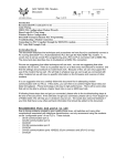
1
Sinking and Sourcing Concepts
When choosing the type of input or output
module
for
your
system
(or
DL05/DL06/DL105 I/O type), it is very
important to have a solid understanding of
sinking and sourcing concepts. Use of
these terms occurs frequently in discussion
of input or output circuits. It is the goal of
this section to make these concepts easy to
understand, so you can make the right
choice the first time when selecting the type
of I/O points for your application. This
section provides short definitions, followed
by general example circuits.
First you will notice that the diagrams on
this page are associated with only DC
circuits and not AC, because of the reference to (+) and (-) polarities. Therefore,
sinking and sourcing terminology applies
only to DC input and output circuits. Input
and output points that are sinking or
sourcing can conduct current in one direction only. This means it is possible to
connect the external supply and field
device to the I/O point, with current trying
to flow in the wrong direction, and the
circuit will not operate. However, the
supply and field device can be connected
every time based on an understanding of
sourcing and sinking.
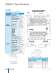
The figure below depicts a sinking input.
To properly connect the external supply, it
must be connected so the input provides a
path to supply common(-). So, start at the
PLC input terminal, follow through the
input sensing circuit, exit at the common
terminal, and connect the supply (-) to the
common terminal. By adding the switch
between the supply (+) and the input, the
circuit is completed. Current flows in the
direction of the arrow when the switch is
closed.
By applying the circuit principles to the four
possible combinations of input/output
sinking/sourcing types, there are four
circuits, as shown above. The common
terminal is the terminal that serves as the
common return path for all I/O points in
the bank.
Input
(s inking)
+
Common
Volume 14
e36-2
Appendix
S inking Input
S inking Output
(IE C: pos itive logic)
(IE C: negative logic)
Input
Output
+
--
Input
S ensing
Common
Output
S witch
+
--
P LC
S ourcing Input
S ourcing Output
(IE C: negative logic)
(IE C: pos itive logic)
Common
Common
+
--
Load
NP N
Common
P LC
Input
S ensing
Input
Output
S witch
+
P NP
Output
P LC
Sink/source I/O circuits combine sinking
and sourcing capabilities. This means that
the I/O circuitry in the PLC will allow
current to flow in either direction, as shown
at the right. The common terminal
connects to one polarity, and the I/O point
connects to the other polarity (through the
field device). This provides flexibility in
making connections to your field power
supply. Please note:
• Wire all I/O points with a shared common
as either sinking or sourcing.
• Do not use an AC power supply on a DC
sink/source I/O point.
-Load
P LC
S ink/S ource Input
(IE C: pos ./neg. logic)
Common
+ --
Input
S ensing
OR
-- +
Input
P LC
S ink/S ource Output
(IE C: pos ./neg. logic)
Common
Output
S witch
P NP /NP N
Output
+ -OR
-- +
Load
P LC
Field device examples - 3 wire connections
NPN (Sinking)
Field Device Example
+
P LC
Input
S ensing
--
Sinking = provides a path to supply common (-)
Sourcing = provides a path to supply source (+)
Sensor
24VDC
+ –
Output
–
(NPN) Current Sinking
Field Device
DC Sourcing Input Module
Common
Input
PNP (Sourcing)
Field Device Example
+
Optical
Isolator
Current Sourcing
Configuration
Sensor
24VDC
+ –
Output
–
DC Sinking Input Module
Common
Input
Optical
Isolator
Current Sinking
Configuration
(PNP) Current Sourcing
Field Device
1 - 80 0 - 633 - 0405