1
Sinking and Sourcing Concepts
Common
terminals and
how to use them
In order for a PLC I/O circuit to operate,
current must enter at one terminal and
exit at another. This means at least two
terminals are associated with every I/O
point. In the figure at the right, the input
or output terminal is the main path for the
current. One additional terminal must
provide the return path to the power
supply. Together, the main path and the
return path create a loop, or a complete
circuit for current to flow.
If there was unlimited space and budget
for I/O terminals, then every I/O point
could have two dedicated terminals.
However, providing this level of flexibility
is not practical or even necessary for most
applications. So, most input or output
points on PLCs are in groups that share
the return path (called commons). The
figure at the right shows a group (or
bank) of four input points that share a
common return path. In this way, the four
inputs require only five terminals instead
of eight.
NOTE: Assuming all input circuits have a similar
resistance, the current at the common terminal is
four times greater than the current at any one of the
inputs. This effect is especially important to note for
output circuits, where the current through a common
terminal can reach several amperes. You will need
to decide whether to fuse each output point individually, or to put a fuse in the common terminal path.
P LC
Main P ath
Field
Device
(I/O Point)
+
I/O
Circuit
--
Company
Information
Systems
Overview
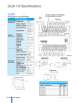
grouped into banks that share a common
return path. The best indication of I/O
common grouping is on the wiring label.
Sample DL05, DL06 and DL105 wiring
labels and their meanings are shown
below.
R eturn P ath
Input 1
Field I/O
Software
C-more &
other HMI
Drives
Soft
Starters
Input
S ensing
Motors &
Gearbox
Input 2
Steppers/
Servos
Input 3
Motor
Controls
Input 4
AC s upply
12--24VDC
INPUT
TB
+
--
Programmable
Controllers
A
0
1
2
3
B
4
5
6
7
0
1
2
3
DL405 input
module shown
4
5
6
7
D4--16ND2
Common
AC or DC s upply
10.2-- 26.4VDC
4-- 12mA
4
Wiring labels
and how to
interpret them
1
5
Encoders
2
6
Current
Sensors
3
7
CB
4
0
Input S witch
DL205, DL305, DL 405 - Most DL205,
DL305 and DL405 input and output
modules group their I/O points into
banks that share a common return path.
The best indication of I/O common
grouping is on the wiring label, such as
the one shown at the right. The miniature
schematic shows two circuit banks with
eight input points in each. The common
terminals are labeled “CA” and “CB,”
respectively.
In the wiring label example, the positive
terminal of a DC supply connects to the
common terminals. Some of the symbols
you will see on wiring labels and their
meanings are shown at the right.
Pressure
Sensors
5
1
6
2
Output Load
7
3
Temperature
Sensors
L
Pushbuttons/
Lights
Process
Relays/
Timers
Comm.
Terminal
Blocks &
Wiring
Power
Circuit
Protection
Input Bank (DL05)
DL05/DL06/DL105 — Most DL05, DL06
and DL105 input and output circuits are
I/O Common Grouping Bar (DL105)
Photo
Sensors
Limit
Switches
CA
0
DC s upply
-- +
Proximity
Sensors
Enclosures
Tools
Two banks of four inputs and two banks of three outputs (DL05)
Pneumatics
Safety
Appendix
Product
Index
Two banks of four inputs and one bank of two (DL105)
Volume 14
w w w. a u to m a t i o n d i re c t . c o m
Appendix
e36-3
Part #
Index