1
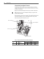
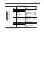
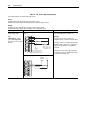
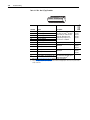
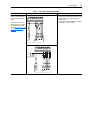
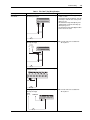
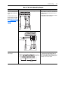
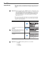
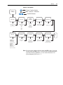
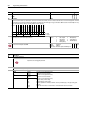
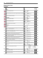
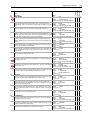
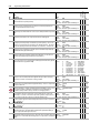
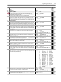
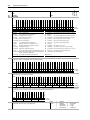
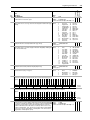
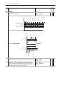
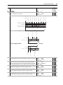
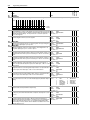
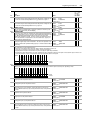
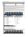
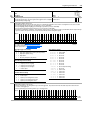
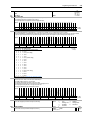
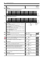
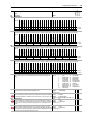
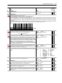
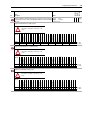
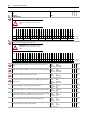
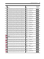
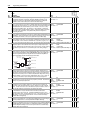
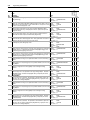
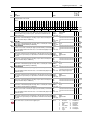
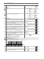
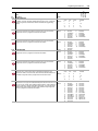
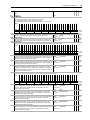
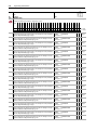
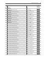
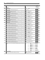
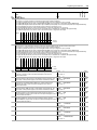
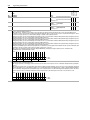
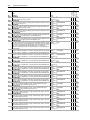
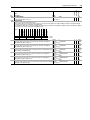
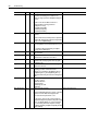
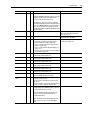
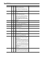
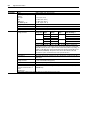
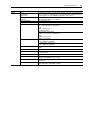
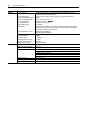
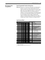
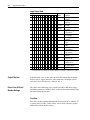
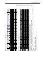
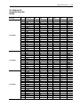
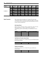
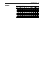
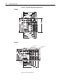
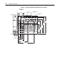
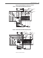
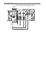
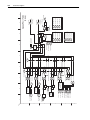
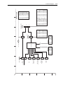
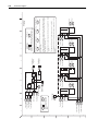
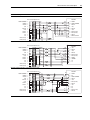
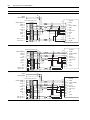
824
Local I/O Status
Values
826
827
828
830
831
832
833
834
835
836
837
838
Reserved
Reserved
Reserved
Reserved
LogixPresent
DigIn 3
DigIn 2
DigIn 1
Enable In
Reserved
Reserved
Reserved
Reserved
0 0 0 0 0 0 0 0 0 0 0 0 0 0 0 0 0 0 0 0 0 0 0
31 30 29 28 27 26 25 24 23 22 21 20 19 18 17 16 15 14 13 12 11 10 9
0
8
0
7
0
6
0
5
0
4
0
3
0
2
0
1
0
0
0 = True
1 = False
Units:
Default:
Min/Max:
Comm Scale:
Default:
Min
Max:
Comm Scale:
Default:
Min/Max:
Comm Scale:
Default:
Min:
Max:
Comm Scale:
mSec
✓ ✓ Real
8.0000/0.0000
15.5000
x1
00000000000000000000000000000000 ✓ ✓ 32-bit
00000000000000000000000000000000
Boolean
11111111111111111111111111111111
x1
0
✓ ✓ 16-bit
-32/31
Integer
x1
00000000000000000000000000000000
32-bit
00000000000000000000000000000000
Boolean
11111111111111111111111111111111
x1
Units:
DigIn1 Debounce
Sets the value of the debounce filter for Digital Input 1. The filter requires the input signal Default:
to be stable for the specified time period. Input transitions within the filter time setting will Min/Max:
be ignored.
Comm Scale:
Default:
DigIn2 Data
Sets the value of Parameter 832 [DigIn 2 Src Data], except for the bit controlled by bit 2 Min:
[DigIn 2] of Parameter 824 [Local I/O Status].
Max:
Comm Scale:
Default:
DigIn2 Bit
Selects the bit, in Parameter 832 [DigIn 2 Src Data], which is controlled by bit controlled Min/Max:
by bit 2 [DigIn 2] of Parameter 824 [Local I/O Status].
Comm Scale:
Default:
DigIn2 User Data
Provides a source of data controlled by bit 2 [DigIn 2] of Parameter 824 [Local I/O Status]. Min:
Max:
Link to a Read-Write parameter and enter a value of 13 in Parameter 839 [DigIn 2 Sel] to Comm Scale:
activate this function.
Units:
DigIn2 Debounce
Sets the value of the debounce filter for Digital Input 2. The filter requires the input signal Default:
to be stable for the specified time period. Input transitions within the filter time setting will Min/Max:
Comm Scale:
be ignored.
Default:
DigIn3 Data
Sets the value of Parameter 836 [DigIn 3 Src Data], except for the bit controlled by bit 3 Min:
Max:
[DigIn 3] of Parameter 824 [Local I/O Status].
Comm Scale:
Default:
DigIn3 Bit
Selects the bit, in Parameter 836 [DigIn 3 Src Data], which is controlled by bit controlled Min/Max:
Comm Scale:
by bit 3 [DigIn 3] of Parameter 824 [Local I/O Status].
Default:
DigIn3 User Data
Provides a source of data controlled by bit 3 [DigIn 3] of Parameter 824 [Local I/O Status]. Min:
Max:
Link to a Read-Write parameter and enter a value of 13 in Parameter 840 [DigIn 3 Sel] to Comm Scale:
activate this function.
Units:
DigIn3 Debounce
Sets the value of the debounce filter for Digital Input 3. The filter requires the input signal Default:
to be stable for the specified time period. Input transitions within the filter time setting will Min/Max:
be ignored.
Comm Scale:
Default:
DigIn 1 Sel
Enter or write a value to select the function of digital input 1.
Options:
mSec
✓ ✓ Real
8.0000
0.0000/15.5000
x1
00000000000000000000000000000000 ✓ ✓ 32-bit
Boolean
00000000000000000000000000000000
11111111111111111111111111111111
x1
0
✓ ✓ 16-bit
Integer
-32/31
x1
00000000000000000000000000000000
32-bit
00000000000000000000000000000000
Boolean
11111111111111111111111111111111
Inputs & Outputs Digital Inputs
En In Debounce
Sets the value of the debounce filter for the Enable input. The filter requires the input
signal to be stable for the specified time period. Input transitions within the filter time
setting will be ignored.
DigIn1 Data
Sets the value of Parameter 828 [DigIn 1 Src Data], except for the bit controlled by bit 1
[DigIn 1] of Parameter 824 [Local I/O Status].
DigIn1 Bit
Selects the bit, in Parameter 828 [DigIn 1 Src Data], which is controlled by bit controlled
by bit 1 [DigIn 1] of Parameter 824 [Local I/O Status].
DigIn1 User Data
Provides a source of data controlled by bit 1 [DigIn 1] of Parameter 824 [Local I/O Status].
Link to a Read-Write Parameter and enter a value of 13 in Parameter 838 [DigIn 1 Sel] to
activate this function.
829
Reserved
Reserved
Reserved
Output Relay
Aux Out 1
Aux Out 2
VP TP1 Out
VP TP2 Out
Watch Dog
Reserved
Reserved
Reserved
Reserved
Reserved
Reserved
Reserved
Reserved
Reserved
Default
Bit
VPL Gate Ena
Displays the status of the local I/O.
Options
825
3-77
Data Type
Name
Description
Read-Write
No.
Linkable
Programming and Parameters
mSec
✓ ✓ Real
8.0000
0.000015.5000
x1
00000000000000000000000000000000 ✓ ✓ 32-bit
Boolean
00000000000000000000000000000000
11111111111111111111111111111111
x1
0
✓ ✓ 16-bit
Integer
-32/31
x1
00000000000000000000000000000000
32-bit
00000000000000000000000000000000
Boolean
11111111111111111111111111111111
x1
mSec
8.0000
0.0000/15.5000
x1
14
“PreChrg/Disc”
0
“Not Used”
1
“Normal Stop”
2
“Start”
3
“Run”
4
“Clear Faults”
5
“Stop - CF”
6
“Jog 1”
7
“Jog 2”
✓ ✓ Real
8
9
10
11
12
13
14
“Fwd/Reverse”
“CurLim Stop”
“Coast Stop”
“Aux Fault”
“AuxFault Inv”
“User Select”
“PreChrg/Disc”