1
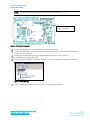
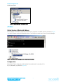
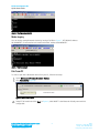
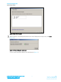
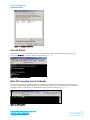
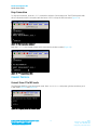
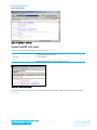
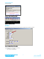
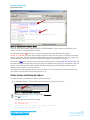
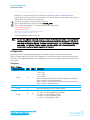
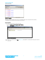
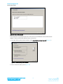
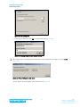
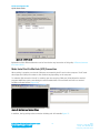
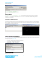
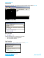
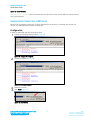
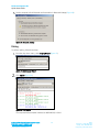
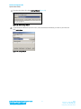
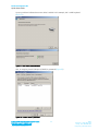
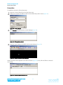
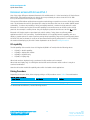
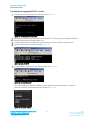
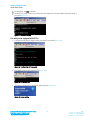
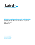
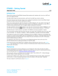
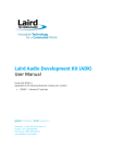
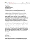
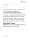
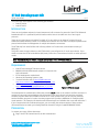
BT740 Development Kit Quick Start Guide v1.2 This Quick Start Guide applies to the following part numbers: DVK-BT740-SA DVK-BT740-SC INTRODUCTION There are two hardware variants (on board antenna and uFL connector for external) of the BT740 Enhanced Data Module (BTv 2.1 specification) which interface with a host via an UART and one of two logical protocols. There are two logical protocols called AT and MP. AT is very similar to the Hayes AT protocol found in traditional modems allowing control of one Bluetooth connection at a time. MP is a multipoint packet-based protocol which allows the management of multiple simultaneous connections. The BT740 ship from Laird facilities with a factory default in AT mode with communications setting of 9600,N,8,1. This guide covers the topics below on the BT740 which is preconfigured in AT mode at production. If you chose to convert the BT740 to MultiPoint (MP) mode, follow the Convert Protocol section to switch protocol modes. Note: Detailed description of both protocols can be found in the BT740 User Manual. REQUIREMENTS DVK-BT740 including BT740 carrier board BRBLU03-010A0 USB Bluetooth adapter or Computer with built-in Bluetooth BT740 development motherboard Windows XP Operating System or later Terminal Software such as Laird / EZURiO terminal http://www.lairdtech.com/zips/LairdTerminal_v6_9_0.zip Laird’s MpBtHost utility (if using MultiPoint functionality) http://www.lairdtech.com/zips/MpBtHost_v3_5_0.zip RS232 cable or USB-RS232 adaptor Figure 1: BT740-SA Module The development kit motherboard’s USB socket provides ONLY power to the module. A RS232 connection is required to have serial communications with the module on the carrier board. Laird provides a terminal emulator program called Laird / EZURiO Terminal for AT mode operation but you can use your preferred terminal emulator program in its place. Another program Laird provides is MpBtHost for multipoint (MP) mode operation. This example uses the Microsoft Bluetooth stack and software that comes with Windows 7. If your computer has built-in Bluetooth support, you can modify the computer aspect of the procedure documented below to match your existing Bluetooth instead of using the supplied BRBLU03-010A0. PREPARATION To prepare your setup, follow these steps: Plug in the BT740 Carrier Board to the DVK motherboard. Embedded Wireless Solutions Support Center: http://ews-support.lairdtech.com www.lairdtech.com/bluetooth 1 Laird Americas: +1-800-492-2320 Europe: +44-1628-858-940 Hong Kong: +852 2923 0610 BT740 Development Kit Quick Start Guide NOTE: The carrier board plugs into 40-pin Hirose connector as shown in Figure 2. Connector receptacle for BT740 carrier board Figure 2: Carrier board connector Connect RS232/USB-RS232 to the computer and development board. Connect the USB cable to the computer and development board. TP2 is the power switch and there is an LED for power indication. Install your preferred terminal program. We recommend using Laird / Ezurio Terminal. Install MpBtHost, if utilising MP mode. Check your Device Manager to determine whether or not your computer is equipped with Bluetooth. Figure 3: Device Manager Plug in the BRBLU03-010A0 if your computer is not equipped with Bluetooth Embedded Wireless Solutions Support Center: http://ews-support.lairdtech.com www.lairdtech.com/bluetooth 2 Laird Americas: +1-800-492-2320 Europe: +44-1628-858-940 Hong Kong: +852 2923 0610 BT740 Development Kit Quick Start Guide Figure 4: Device Manager - Bluetooth radios AT MODE Obtain Version & Bluetooth Address In this example, the module is physically connected to the computer on COM47. See the commands in Figure 5 to check firmware version and Bluetooth address. The COM port number can be found in Device Manager. Figure 5: Commands for checking firmware version and BT address Configuration By default, BT740 is configured as SPP enabled, Discoverable and Connectable, SSP + IO_CAP_NO_INPUT_NO_OUTPUT (Figure 6). Embedded Wireless Solutions Support Center: http://ews-support.lairdtech.com www.lairdtech.com/bluetooth 3 Laird Americas: +1-800-492-2320 Europe: +44-1628-858-940 Hong Kong: +852 2923 0610 BT740 Development Kit Quick Start Guide Figure 6: Configuration defaults Make Inquiry You can inquiry nearby Bluetooth devices by issuing AT+BTIN. In Figure 7, BT740 (MAC address: 0016A40605F1) found another Laird module with MAC address 0016A40605F1. Figure 7: Inquiry example Pair from PC To order to pair with a Bluetooth device from your PC, follow these steps: Access Devices and Printers > Bluetooth Devices Click Add a device (Figure 8). Figure 8: Select Add a device Select BT740 module and click Next. In Figure 9, Laird 0605F7 is the Bluetooth Friendly name which is configurable. Embedded Wireless Solutions Support Center: http://ews-support.lairdtech.com www.lairdtech.com/bluetooth 4 Laird Americas: +1-800-492-2320 Europe: +44-1628-858-940 Hong Kong: +852 2923 0610 BT740 Development Kit Quick Start Guide Figure 9: Select the BT module When the device is successfully added and the two virtual COM ports are ready to use, click Close (Figure 10). Figure 10: Virtual COM ports - ready to use The two virtual COM ports display in the COM Ports tab (Figure 11). Embedded Wireless Solutions Support Center: http://ews-support.lairdtech.com www.lairdtech.com/bluetooth 5 Laird Americas: +1-800-492-2320 Europe: +44-1628-858-940 Hong Kong: +852 2923 0610 BT740 Development Kit Quick Start Guide Figure 11: Displayed COM ports Pair with Module After inquiry, issue “AT+BTW<peer address>” to start pairing. PAIR 0 indicates pairing is successful. The purpose of AT+BTT? is to check if the link key is stored (Figure 12). Figure 12: Pairing with the module Make SPP Connection from PC to Module In the previous section, the Windows BT stack has allocated COM32 as the outgoing virtual COM port. You can open COM32 with a terminal program to make an SPP connection to the module which is on COM47; a transparent UART communication is established between these two COM ports (Figure 13). Figure 13: SPP connection Embedded Wireless Solutions Support Center: http://ews-support.lairdtech.com www.lairdtech.com/bluetooth 6 Laird Americas: +1-800-492-2320 Europe: +44-1628-858-940 Hong Kong: +852 2923 0610 BT740 Development Kit Quick Start Guide The DCD LED indicates SPP connection is established (Figure 14). Figure 14: DCD LED indication Make SPP Connection from Module to Module Another Laird module with MAC address 0016A40605F1 is physically connected on COM24 (Figure 15). Figure 15: Module to module connection In order to make an SPP connection from a module with MAC address 0016A40605F7 to another module with MAC address 0016A40605F1, issue ATD<peer MAC address> (Figure 16). Figure 16: ATD<peer MAC address> issued A transparent UART communication is established between these 2 COM ports. DCD LED indicates SPP connection is established (Figure 17). Figure 17: DCD LED indicator Embedded Wireless Solutions Support Center: http://ews-support.lairdtech.com www.lairdtech.com/bluetooth 7 Laird Americas: +1-800-492-2320 Europe: +44-1628-858-940 Hong Kong: +852 2923 0610 BT740 Development Kit Quick Start Guide Drop Connection To drop the connection, issue the “^^^” command to switch to Connected mode. The BT740 responds with OK to indicate the switch is successful and then issues “ATH” to drop the SPP connection (Figure 18). Figure 18: Drop connection command Note that “^^^” is also treated as data and is transmitted to another module (Figure 19). Figure 19: ^^^ transmitted as data CONVERT PROTOCOL Convert from AT to MP mode The S Register (9255) is to set the protocol mode. Send “ATS9255=1” and power cycle the module to put it in MP mode (Figure 20 and Figure 20). Figure 20: S Register (9255) for protocol mode Embedded Wireless Solutions Support Center: http://ews-support.lairdtech.com www.lairdtech.com/bluetooth 8 Laird Americas: +1-800-492-2320 Europe: +44-1628-858-940 Hong Kong: +852 2923 0610 BT740 Development Kit Quick Start Guide Figure 21: MpBTHost – MP mode Convert from MP to AT mode There is an S register (0xFF) to set the protocol mode (Figure 22). 255 (FF) 1 2 Host Communications Protocol 1 = Multipoint Packet Protocol 2 = AT Protocol Automatically saved to non-vol memory on write Figure 22: S Reg (protocol mode) To put the module in AT mode, you can set the register (0xFF) value to 0x02, and power cycle the module (Figure 23). Embedded Wireless Solutions Support Center: http://ews-support.lairdtech.com www.lairdtech.com/bluetooth 9 Laird Americas: +1-800-492-2320 Europe: +44-1628-858-940 Hong Kong: +852 2923 0610 BT740 Development Kit Quick Start Guide Figure 23: S Reg to put module in AT mode Figure 24: Converted to AT mode MP MODE The development board with the BT740 carrier board is connected to the computer on COM47. Figure 25: Multipoint Bluetooth Host window This BT740 module is loaded with the following: Firmware: 1.3.1.1.1.0.258 MAC address: 0016A40605F7. Embedded Wireless Solutions Support Center: http://ews-support.lairdtech.com www.lairdtech.com/bluetooth 10 Laird Americas: +1-800-492-2320 Europe: +44-1628-858-940 Hong Kong: +852 2923 0610 BT740 Development Kit Quick Start Guide Figure 26: Firmware version and MAC address There are small LED emulation graphics labelled CTS/RTS/DCD/RI/RTS. These reflect the actual state of the modem control lines as asserted by the module. For command packets (red lines), note an extra spacing after the fourth character (for example: 05 00 17 7F 00). This extra space highlights the fact that the first four bytes of a multipoint command packet is the header, with the third byte corresponding to the CMD_ID as described in the user manual, and all bytes after the fourth byte constitute data fields as defined for that particular command. For responses (blue lines), note the extra spacing after the fifth byte (for example: 0B 00 02 7F 00). This extra space highlights the fact that the first five bytes is the header and the fifth byte, as described in the user manual, is the status byte (00 signifies MPSTATUS_OK). Everything after the fifth byte constitutes data as defined for each response in the user manual. The asynchronous event message shown in green consists of a four byte header and data as defined in the user manual. The third byte of the message is the EVT_ID. Obtain Version and Bluetooth Address To obtain the version and Bluetooth address, follow these steps: In MpBtHost window, click the paint brush icon button to clear the log window. Figure 27: Configuration window drop-down Click the dropdown box (Figure 27) and select Information. Click Tx (Figure 27). The following information should display: >70 915.211 05 00 17 7F 00 CMD_INFORMATION <70 000.125 0E 00 17 7F 00 00 8101011100D70601 RSP_INFORMATION (MPSTATUS_OK) Embedded Wireless Solutions Support Center: http://ews-support.lairdtech.com www.lairdtech.com/bluetooth 11 Laird Americas: +1-800-492-2320 Europe: +44-1628-858-940 Hong Kong: +852 2923 0610 BT740 Development Kit Quick Start Guide //Module Firmware Version : 1.1.1.1.1.215:0 // ---- PlatformId, CclVer, AppVer, Dev'perId, BranchId, Build : Twig Depending on the firmware version, the final part of the blue line 8101011100D70601 varies depending on the version number. The format of the version information is described in the main user manual and is also explained in grey font above. Clear the log window by clicking the paint brush icon. Click on the dropdown box again and select Read BD_ADDR. Click on the button labelled “Tx” and should see the following activity: >70 364.465 04 00 02 7F CMD_READ_BDADDR <70 000.125 0B 00 02 7F 00 0016A4FEF000 RSP_READ_BDADDR (MPSTATUS_OK) The six byte Bluetooth address is unique. Note: For each line, whether command, response or event, the first character (either < or>) signifies the direction of the packet. > signifies a command from host to module and < signifies a response or event from the module to the host. A number is located after the < or >; this number is the COM port number. The following field (for example, 364.465 and 000.125) is the time elapsed (in milliseconds) since the last packet (regardless of direction). Configuration By default, BT740 is configured as discoverable, connectable, Serial Port Profile (SPP) enabled, and SSP+IO_CAP_NO_INPUT_NO_OUTPUT. No configuration is required for the SPP connection demonstrated in this section. For a detailed description of IO capability, refer to the user manual and the IO Capability section in this guide. S Registers Table 1: S Registers RegNo Dec (Hex) Min Max 3 (03) 0 3 4 (04) 5 (05) 0 0 1 2 6 (06) 12 15 Embedded Wireless Solutions Support Center: http://ews-support.lairdtech.com www.lairdtech.com/bluetooth Description Server Profile record Mask Bit 0 = SPP Bit 1 = HID Bit 2 = HDP If HID is enabled, see S Reg 39 for further configuration options in terms of device or host implementation. If HDP is enabled, see S Reg 70 for further configuration options in terms of agent or manager services. Default Connectable mode on power up/reset Default Discoverable mode on power up/reset Default Security mode on power up/reset 12 = SSP + IO_CAP_NO_INPUT_NO_OUTPUT 13 = SSP + IO_CAP_DISPLAY_YES_NO 14 = SSP + IO_CAP_KEYBOARD_ONLY 15 = SSP + IO_CAP_DISPLAY_ONLY 12 Laird Americas: +1-800-492-2320 Europe: +44-1628-858-940 Hong Kong: +852 2923 0610 BT740 Development Kit Quick Start Guide Figure 28: S Registers SReg read on these registers return 01, 01, 01, and 0x0C, which can be interpreted as Discoverable, Connectable, SPP, and SSP+IO_CAP_NO_INPUT_NO_OUTPUT. Pair from PC To pair with a Bluetooth device, follow these steps: Access Devices and Printers > Bluetooth Devices Click Add a device (Figure 29). Figure 29: Select Add a device Select BT740 module and click Next. In Figure 30, Laird 0605F7 is the Bluetooth Friendly name which is configurable. Embedded Wireless Solutions Support Center: http://ews-support.lairdtech.com www.lairdtech.com/bluetooth 13 Laird Americas: +1-800-492-2320 Europe: +44-1628-858-940 Hong Kong: +852 2923 0610 BT740 Development Kit Quick Start Guide Figure 30: Add a device window If the computer is not equipped with built-in Bluetooth and the BRBLU03-010A0 USB Bluetooth adapter is used, the following additional steps are required: a. From the Select a pairing option window, select Enter the device’s pairing code (Figure 31). Figure 31: Select a pairing option window b. Enter 1234 as the pairing code (Figure 32). Embedded Wireless Solutions Support Center: http://ews-support.lairdtech.com www.lairdtech.com/bluetooth 14 Laird Americas: +1-800-492-2320 Europe: +44-1628-858-940 Hong Kong: +852 2923 0610 BT740 Development Kit Quick Start Guide Figure 32: Enter pairing code c. In the pop-up dialog box, click Ok to complete the pairing (Figure 33). Figure 33: Incoming Pairing PinCode Request window When the device is successfully added and the two virtual COM ports are ready to use, click Close (Figure 34). Figure 34: Virtual COM ports - ready to use The two virtual com ports display in the COM Ports tab (Figure 35). Embedded Wireless Solutions Support Center: http://ews-support.lairdtech.com www.lairdtech.com/bluetooth 15 Laird Americas: +1-800-492-2320 Europe: +44-1628-858-940 Hong Kong: +852 2923 0610 BT740 Development Kit Quick Start Guide Figure 35: COM Ports tab Explanation of this different behaviour can be found at the very last section of this guide, Difference between BTv2.0 and BTv2.1. Make Serial Port Profile Data (SPP) Connection When pairing is complete, two virtual COM ports are created by the BT stack on the computer. The BT stack also assigns the COM port numbers so the numbers vary depending on the computer. To make the SPP connection from PC to module, open the outgoing COM port (COM 40) with a terminal program. MpBTHost opens a new dialog box which enables data to be sent back and forth in a terminal emulation window fashion (Figure 36). Figure 36: MpBTHost and Terminal dialogs In addition, the log activity at the connection initiating end will resemble Figure 37. Embedded Wireless Solutions Support Center: http://ews-support.lairdtech.com www.lairdtech.com/bluetooth 16 Laird Americas: +1-800-492-2320 Europe: +44-1628-858-940 Hong Kong: +852 2923 0610 BT740 Development Kit Quick Start Guide Figure 37: Log activity “0D 00 88 7F 07 C01885DAE532 1101” is actual serial data sent from the module on its UART interface. 0x07 indicates the Channel ID, and C01885DAE532 is the BT MAC address making the SPP connection to the module. Send Data in Both Directions Assuming that a data connection exists using the steps shown in the previous section, you should be able to type a message in terminal emulation window (COM47) and see the data appear at the other end (COM40). For example type in Hello and type Send… Figure 38: COM 47 and COM 40 exchanging data “07 07 48656C6C6F” is the actual serial data that should be sent to the module in order send Hello over the BT SPP connection (Figure 39): First 0x07 – Indicates the total length of the packet. Second 0x07 – Indicates the channel ID. 48656C6C6F – “Hello” in hex value. Figure 39: Actual serial data Embedded Wireless Solutions Support Center: http://ews-support.lairdtech.com www.lairdtech.com/bluetooth 17 Laird Americas: +1-800-492-2320 Europe: +44-1628-858-940 Hong Kong: +852 2923 0610 BT740 Development Kit Quick Start Guide When we type AC on COM40, AC is displayed on the terminal emulation window (COM47) (Figure 40). Figure 40: Terminal emulation window The following (Figure 41) is the log window for the exchange above (Figure 40). Figure 41: Log window <47 385.557 03 07 41 <47 001.060 03 07 43 These two lines are the actual serial data sent from the module: 0x03 – Indicates the total length of the packet. 0x07 – Indicates the channel ID 0x41 and 0x43 – The hex values of AC. Drop Connection To drop the connection, close the terminal program on COM40 (Figure 42). Embedded Wireless Solutions Support Center: http://ews-support.lairdtech.com www.lairdtech.com/bluetooth 18 Laird Americas: +1-800-492-2320 Europe: +44-1628-858-940 Hong Kong: +852 2923 0610 BT740 Development Kit Quick Start Guide Figure 42: Closed Terminal “06 00 86 7F 07 03” is the serial data that should be sent from the module UART to indicate channel 0x07 is disconnected. SIMULTANEOUS CONNECTIONS IN MP MODE When BT740 is operating in MP mode, it allows simultaneous connections. For example, the module can function as a HID keyboard and make or accept SPP. Configuration In order to enable HID and SPP, follow these steps: Change the S Register (0x03) to 0x03 (Figure 43). Figure 43: Change the S Register Store the S Register (Figure 44). Figure 44: Store the S Register Reboot the module. Click Reset (Figure 45). Figure 45: Reset button Embedded Wireless Solutions Support Center: http://ews-support.lairdtech.com www.lairdtech.com/bluetooth 19 Laird Americas: +1-800-492-2320 Europe: +44-1628-858-940 Hong Kong: +852 2923 0610 BT740 Development Kit Quick Start Guide Set the computer built-in Bluetooth as Discoverable in Bluetooth Settings (Figure 46). Figure 46: Bluetooth Settings Pairing To perform pairing, follow these steps: From the drop-down menu, select Inquiry Wizard (Figure 47). Figure 47: Select Inquiry Wizard Click Inquire (Figure 48). Figure 48: Click Inquire The computer Bluetooth (MAC address C01885DAE532) is found. Embedded Wireless Solutions Support Center: http://ews-support.lairdtech.com www.lairdtech.com/bluetooth 20 Laird Americas: +1-800-492-2320 Europe: +44-1628-858-940 Hong Kong: +852 2923 0610 BT740 Development Kit Quick Start Guide From the drop-down list, select Pairing Wizard (Figure 49). Figure 49: Select Pairing Wizard In the Bluetooth Address drop-down menu, select the Bluetooth Address you want to pair with and click Pair Initiate. Figure 50: Pairing Wizard Embedded Wireless Solutions Support Center: http://ews-support.lairdtech.com www.lairdtech.com/bluetooth 21 Laird Americas: +1-800-492-2320 Europe: +44-1628-858-940 Hong Kong: +852 2923 0610 BT740 Development Kit Quick Start Guide A pop-up window indicates that a new device is added. In this example, this is a HID keyboard (Figure 51). Figure 51: New device pop-up window Also, an outgoing virtual COM port (COM32) is generated (Figure 52). Figure 52: COM32 device is generated Embedded Wireless Solutions Support Center: http://ews-support.lairdtech.com www.lairdtech.com/bluetooth 22 Laird Americas: +1-800-492-2320 Europe: +44-1628-858-940 Hong Kong: +852 2923 0610 BT740 Development Kit Quick Start Guide Connection To establish a connection, follow these steps: Open the Connect Wizard from the drop-down menu. Select your computer and HID from the Connect Wizard drop-down menus (Figure 53). Figure 53: Connect Wizard Click Connect. An HID emulation window displays (Figure 54). Figure 54: HID emulation window Open the virtual COM port (COM32) with terminal software (Figure 55). Figure 55: Terminal software virtual COM port Another terminal window appears for the SPP connection (Figure 56). Here, HID and SPP are connected concurrently. Figure 56: Second terminal window for SPP Embedded Wireless Solutions Support Center: http://ews-support.lairdtech.com www.lairdtech.com/bluetooth 23 Laird Americas: +1-800-492-2320 Europe: +44-1628-858-940 Hong Kong: +852 2923 0610 BT740 Development Kit Quick Start Guide DIFFERENCE BETWEEN BTV2.0 AND BTV2.1 One of the major differences between Bluetooth v2.0 and Bluetooth v2.1 is the introduction of Simple Secure Pairing (SSP). SSP simplifies pairing so it doesn’t rely on a pre-shared pin code as it was in BTv2.0. With BTv2.1, all connections are forced to be encrypted. SSP uses the Diffie-Hellman public/private encryption methodology to expedite a common 128 bit key at both ends. This eliminates the need for pre-shared pin codes but introduces the ‘man in the middle’ (MITM) attack vulnerability. To reduce the possibility of being successfully attacked, a random six-digit passcode is used. Bluetooth v2.1 devices are required to have I/O capability to ensure that users can interact to the six digit passcode. One example is mobile phones: they can display the passcode and the user can click Yes to pair. Bluetooth v2.0 devices require a pre-shared pin code for pairing. Today, there are still many M2M applications with BT v2.0 connectivity. These M2M devices do not typically have I/O capability, such as a display or Yes/No options for users to perform pairing. Most importantly, they can be in hard-to-reach places. On the BT740, the pre-shared pin code can be pre-entered before pairing takes place if it is a BT v2.0 device the module is attempting to pair with. Further explanation can be found in Pairing Procedure. I/O capability The I/O capability of the module is set via S Register 6 (9006 in AT mode) with the following values: 12(0x0C) = No I/O capability 13(0x0D) = Display with Yes/No 14(0x0E) = Keyboard only 15(0x0F) = Display Only When both ends are Keyboard only, a pre-shared six digit number can be entered. When both are Display only, it is unlikely the devices have services that are useful to either. It may be a contrived combination. Users should set the module I/O capability value which is suitable to their applications. Pairing Procedure Depending on the peer device, either a legacy pairing or a SSP procedure occurs. Table 2 lists combinations: Table 2: Pairing procedures Local Device BTM74X BTM74X Peer Device BT 2.1 or later BT 2.0 Pairing SSP Legacy pairing To demonstrate the difference, see the following sections. Embedded Wireless Solutions Support Center: http://ews-support.lairdtech.com www.lairdtech.com/bluetooth 24 Laird Americas: +1-800-492-2320 Europe: +44-1628-858-940 Hong Kong: +852 2923 0610 BT740 Development Kit Quick Start Guide Pair with phone equipped with BT 2.1 or later Configure the module with the AT commands below (Figure 57). Figure 57: Configuration AT commands Pair with two mobile phones: Sony Xperia SP and Nokia E72. The Sony phone is equipped with BT 4.0, while the Nokia phone is equipped with BT 2.0. Configure both phones to be Bluetooth discoverable before pairing. Different responses occur. Issue AT+BTIN to discover these two phones (Figure 58). Figure 58: Issue AT+BTIN Use the following commands to pair with the Xperia SP (Figure 59). Figure 59: Pair with Xperia SP The module displays the passcode 442923; the same passcode should be displayed on the phone. Users are required to compare the passcode displayed (Figure 60). Figure 60: BT pairing request Embedded Wireless Solutions Support Center: http://ews-support.lairdtech.com www.lairdtech.com/bluetooth 25 Laird Americas: +1-800-492-2320 Europe: +44-1628-858-940 Hong Kong: +852 2923 0610 BT740 Development Kit Quick Start Guide On the phone, tap Pair to confirm. On the BT740, issue AT+BTKY to confirm the same passcode is showing. PAIR 0 indicates pairing is successful (Figure 61). Figure 61: Successful pairing Pair with phone equipped with BT 2.0 1. Configure the module for legacy pairing with below commands (Figure 62). Figure 62: Configuration AT commands 2. Issue below command to pair with E72 (Figure 63). Figure 63: AT+BTW to pair 3. The phone prompts user to accept the pairing request (Figure 64). Figure 64: Accept pairing Embedded Wireless Solutions Support Center: http://ews-support.lairdtech.com www.lairdtech.com/bluetooth 26 Laird Americas: +1-800-492-2320 Europe: +44-1628-858-940 Hong Kong: +852 2923 0610 BT740 Development Kit Quick Start Guide 4. Enter the pairing code “1234” Figure 65: Enter pairing code 5. Pairing response indicates pairing is successful (Figure 66). Figure 66: PAIRING is successful ADDITIONAL DOCUMENTATION AND RESOURCES Laird offers a variety of documentation and ancillary information to support our customers through the initial evaluation process and ultimately into mass production. Further documentation is available from http://www.lairdtech.com/products/bt740-series includes: BT740 – Firmware User manual BT740 – Hardware Integration Guide (HIG) DVK-BT740 – User Manual DVK-BT740 – Schematics Software is available in the software downloads tab of the BT740 page: Laird / EZURiO terminal The following article helps explain how to add a Bluetooth device to your Windows 7 computer: http://windows.microsoft.com/en-us/windows7/add-a-bluetooth-enabled-device-to-your-computer For any additional questions or queries, or to receive local technical support for this Development Kit or for the BT740 module series, please contact [email protected]. REVISION HISTORY Revision Date 1.0 1.1 1.2 10 July 2013 16 Aug 2013 7 April 2013 Description Initial Release Minor edits Formatting, revision history, footer. Embedded Wireless Solutions Support Center: http://ews-support.lairdtech.com www.lairdtech.com/bluetooth Initiated By 27 Jonathan Kaye Sue White Dave Drogowski Laird Americas: +1-800-492-2320 Europe: +44-1628-858-940 Hong Kong: +852 2923 0610 BT740 Development Kit Quick Start Guide Embedded Wireless Solutions Support Center: http://ews-support.lairdtech.com www.lairdtech.com/bluetooth 28 Laird Americas: +1-800-492-2320 Europe: +44-1628-858-940 Hong Kong: +852 2923 0610