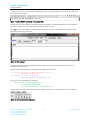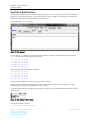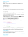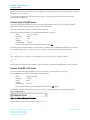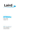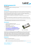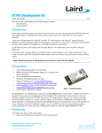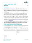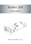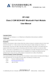
1
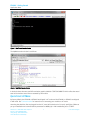
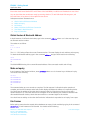
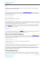
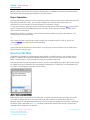
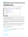
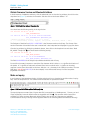
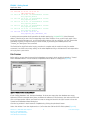
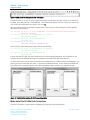
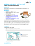
BTM44X – Getting Started Application Note v1.0 INTRODUCTION There are four variants of the BTM44x Enhanced Data module which interface with a host via a UART and one of two logical protocols. The 440 and 442 require an external antenna, and the 441 and 443 have a built-in antenna. All variants have the same firmware image, but are configured at production time to have different logical protocols and UART communication parameters by default. There are two logical protocols called AT (attention) and MP (multipoint). AT is very similar to the Hayes AT protocol found in traditional modems which allows control of one Bluetooth connection at a time. MP is a multipoint packet based protocol which manages multiple simultaneous connections. The 442 & 443 both startup by factory default in AT mode with communications setting of 9600,N,8,1 and the 440 & 441 both startup by factory default in MP mode with communications setting of 115200,N,8,1. Detailed description of both protocols is provided in the BTM44x User Manual available on request. The communication settings allow baud rates to be set in the range 1200 to 921600, parity to be none, odd or even and either 1 or 2 stop bits. In addition, CTS/RTS handshaking is provided and cannot be disabled. The modules are surface mount modules so development kits are available to help learn and prototype with. As there are 4 variants of the module, there are 4 development kits. However, it should be noted that from a hardware perspective the 440 & 442 dev kits are exactly the same and likewise for the 441 & 442 devkits. Only the default settings are different. This application note assumes you have access to two BTM44x development kits and the rest of this document describes how to quickly get started for AT and MP modes. If you have kits which are by default set to a different protocol mode than you want to try, see Convert Protocol which describes how to convert a module to the alternate protocol mode and then resume to the relevant quick start section. PREPARATION Plug both development kits into free USB ports on your Windows PC (XP or later) and allow the USB to Virtual comport drivers to be installed. The dev kits use an FTDI chip and if your PC cannot locate the drivers, you can download them from http://www.ftdichip.com/FTDrivers.htm. After successful install, you should see two new comports under “Ports (COM & LPT)” in Device Manager. Note the COMxx numbers allocated for the two boards. Contact Laird to obtain two PC utilities. One is a custom developed terminal emulator called “Uwterminal” and the other is a custom developed application to drive the module in MP mode called “MpBtHost” The main window for UwTerminal is shown in Figure 1: Americas: +1-800-492-2320 Option 3 Europe: +44-1628-858-940 Hong Kong: +852 2923 0610 www.lairdtech.com/wireless 1 Laird Technologies BTM44X - Getting Started Application Note Figure 1: UwTerminal main window The MpBtHost main window is as follows: Figure 2: MpBtHost main window In both windows there are small LED emulation graphics labelled CTS/RTS/DCD/RI/RTS which reflect the actual state of the modem control lines as asserted by the module. QUICK START: AT MODE By factory default, the BTM440 or BTM442 are shipped in AT mode and the BTM441 or BTM443 are shipped in MP mode. See Convert Protocol for instructions on converting your modules to AT mode. Assuming that both dev kits are plugged into the PC, start UwTerminal twice. For each, specify the COMxx as per your installation and communications parameters as 9600,N,8,1 with handshaking set to CTS/RTS. Americas: +1-800-492-2320 Option 3 Europe: +44-1628-858-940 Hong Kong: +852 2923 0610 www.lairdtech.com/wireless 2 Laird Technologies BTM44X - Getting Started Application Note Ensure the check boxes labelled RTS and DTR are ticked and BREAK, LocalEcho and LineMode are not ticked. You can check that the modules are ready, by ensuring that the CTS and DSR virtual LEDs are green, and DCD and RI are red as shown in the snapshot shown above. Subsequent sections illustrate how to: Obtain Version & Bluetooth Address Make an Inquiry Pair Devices Make a Serial Port Profile Data Connection Send Data in Both Directions Drop a Connection Obtain Version & Bluetooth Address In both instances of UwTerminal windows, type in the command ati3<cr> where <cr> is the enter key to get the firmware version number. The results are as follows: ati3 1.1.1.215.0 OK The 1.1.1.215.0 string reflects the current firmware version. The same displays in each window and may vary. To obtain the Bluetooth address, type in the command ati4<cr> and you should result in the following: ati4 0016A4FEF004 OK The 0016A4FEF004 string is the current Bluetooth address of the connected module and will vary. Make an Inquiry In one instance of UwTerminal window, enter at+bti<cr> where <cr> is the enter key to initiate an inquiry. This results in the following: at+bti 0016A4FEF072 0016A4FEF000 0016A4FEF073 0016A4FEF001 OK The command takes up to ten seconds to complete. The OK response is indication that the operation is complete, and each line between at+bti and the OK displays the Bluetooth address of a responding device. You should see the address of the other dev kit appear in that list. Given that an inquiry process has a random element to it, if the other device does not appear in the list because your location is saturated with discoverable Bluetooth devices, submit the same at+bti<cr> command again to this module. You should not see activity on the other UwTerminal to indicate that it responded to an inquiry from a peer. Pair Devices Before pairing ensure that the trusted device databases are empty in both modules by typing in the command at+btd*<cr> in both instances of UwTerminal. You should see the following: Americas: +1-800-492-2320 Option 3 Europe: +44-1628-858-940 Hong Kong: +852 2923 0610 www.lairdtech.com/wireless 3 Laird Technologies BTM44X - Getting Started Application Note at+btd* OK Ensure the trusted device database is empty in both devices by entering at+btt?<cr> in both instances of UwTerminal. You should see the following: at+btt? OK Initiate pairing from one module to the other by entering at+btw0016a4xxxxxx<cr> where 0016a4xxxxxx is the bluetooth address of the other module. After roughly ten seconds, the initiating instance of UwTerminal should display the following: at+btw0016a4fef005 OK PAIR 0 0016A4FEF005 At the peer end, you should see the following: PAIR 0 0016A4FEF004 Notice that the module sends the OK confirmation to the at+btw command almost immediately. The PAIR 0 responses appear about ten seconds later at both ends almost simultaneously. The PAIR 0 xxx message at one end has the 12-digit Bluetooth address of the peer trusted device. Now check that the pairing information has been added to the trusted device database in both modules by entering at+btt?<cr> in both instances of UwTerminal. You should see ONLY one address line in between at+btt? and the OK response, as follows: at+btt? 0016A4FEF005 OK You can power cycle each module, type in the at+btt?<cr> command and the device displays in the trusted device database given that the database is stored in non-volatile memory. Make a Serial Port Profile Data Connection To make a connection, in one instance of UwTerminal window, type in the command atd0016a4xxxxxx<cr> where <cr> is the enter key and 0016a4xxxxxx is the address of the module in the other devkit. You should see something similar to the following: atd0016a4fef005 CONNECT 0016A4FEF005,1101,> In the UwTerminal instance of the peer device, you should see the following: RING 0016A4FEF004 CONNECT 0016A4FEF004,1101,< The Bluetooth address after the CONNECT string is the Bluetooth address of the peer device and the 1101 is a unique identifier corresponding to serial port profile (SPP) and is a value set by the Bluetooth SIG. At this stage you should see that in both instances of UwTerminals there should now be three green virtual LEDs which show that the module has asserted the DCD modem status line to signify that at least one Bluetooth connection exists in that module. Send Data in Both Directions Assuming that a data connection exists using the steps shown in the previous section and confirmed by the fact that the DCD virtual LED is green, you should be able to type a message in one instance of UwTerminal Americas: +1-800-492-2320 Option 3 Europe: +44-1628-858-940 Hong Kong: +852 2923 0610 www.lairdtech.com/wireless 4 Laird Technologies BTM44X - Getting Started Application Note and see it being echoed in the other instance. Likewise type in a message in the other UwTerminal instance and confirm that the message gets displayed in the other instance. Drop a Connection Assuming that a data connection exists using the steps shown in previous sections and confirmed by the fact that the DCD virtual LED is green, you can drop the Bluetooth connection from either instance of UwTerminal. It is not necessary for the side initiating the connection to drop it. To drop the connection, select any instance of UwTerminal and type the three character ^ ^ ^ ensuring that there is at least half a second delay between each character. As you type each character it echoes at the other instance of UwTerminal. After typing in the third ^ character, at the UwTerminal instance where you typed in that character, the module confirms and responds with: OK At this stage the DCD virtual LED turn green to signify that the data connection is still up. Type in the command ath<cr> . At both ends, the terminal displays: NO CARRIER Confirm that at both ends the DCD virtual LED is no longer green, but has reverted to red to signify that a data connection no longer exists. QUICK START: MP MODE The BTM441 or BTM443 are programmed by factory default in multipoint mode. If your modules are not BTM441 or BTM443, but instead are BTM440 or BTM442 so are in AT mode, then refer to a later section called “Convert Protocol” for instructions to convert your modules to MP mode. Assuming that both dev kits are plugged into the PC, start the utility MpBtHost.exe twice and for each specify the COMxx as per your installation and communications parameters as 115200,N,8,1 with handshaking set to CTS/RTS. A small dialog box appears as shown below: Figure 3: Reset module wizard dialog Either wait for around 10 seconds for the dialog box to timeout and then proceed normally or click on the ‘Go’ button to bypass that timer. The utility sends a few MP commands to identify the module and its Bluetooth address so that appropriate sections of the main window can display that information. Specifically, the bottom right of the status bar (Figure 4) displays the Bluetooth address IF the module is powered and responding at the COM port you specified: Americas: +1-800-492-2320 Option 3 Europe: +44-1628-858-940 Hong Kong: +852 2923 0610 www.lairdtech.com/wireless 5 Laird Technologies BTM44X - Getting Started Application Note Figure 4: Status bar, populated with current Bluetooth data If the Bluetooth address does not display, you most likely will not see any red/blue/green lines in the main log window as follows: Figure 5: UwTerminal log Only proceed if you see the information as above. Note the four virtual LEDs which show the status of the modem lines on the UART. In normal operating conditions, CTS & DSR should be green and DCD &RI should be red. Leave the DTR and RTS checkboxes checked. Messages in red text in the log window are commands from the host to the module. Messages in blue are responses to those commands from the module. Asynchronous event messages from the module to the host are in green. Messages in grey are information added by the utility and do NOT constitute any UART traffic. For command packets (red lines), note an extra spacing after the fourth character. That is to highlight the fact that the first 4 bytes of a multipoint command packet is the header, with the 3rd byte corresponding to the CMD_ID as described in the user manual and all bytes after the 4th byte constitute data fields as defined for that particular command. For responses (blue lines), note the extra spacing after the fifth byte. That is to highlight the fact that the first 5 bytes is the header and the fifth byte as described in the user manual is the status byte (00 signifies MPSTATUS_OK). Everything after the 5th byte constitutes data as defined for each response in the user manual. Asynchronous event messages (green lines) consist of a 4 byte header and data as defined in the user manual. The 3rd byte of the message is the EVT_ID. The following subsections show how to: Drop Connection Obtain Firmware Version and Bluetooth Address (though the startup sequence does it automatically) Make an Inquiry from one module and see the other respond Pair Devices Make a Serial Port Profile Data Connection Send Data in Both Directions Drop Connection Americas: +1-800-492-2320 Option 3 Europe: +44-1628-858-940 Hong Kong: +852 2923 0610 www.lairdtech.com/wireless 6 Laird Technologies BTM44X - Getting Started Application Note Obtain Firmware Version and Bluetooth Address In both instances of MpBtHost windows, click the paintbrush icon to clear the log window, then click on the dropdown box (Figure 6) and select ‘Information’ and then click on the button labeled “Tx”. Figure 6: Paintbrush (clear log) and dropdown box You should see the following activity in the log window: >70 915.211 05 00 17 7F 00 CMD_INFORMATION <70 000.125 0E 00 17 7F 00 00 8101011100D70601 RSP_INFORMATION (MPSTATUS_OK) //Module Firmware Version : 1.1.1.1.1.215:0 // ---- PlatformId, CclVer, AppVer, Dev'perId, BranchId, Build : Twig The final part of the blue line 8101011100D70601 is the firmware version and will vary. The format of the version information is described in the user’s manual and is also interpreted and displayed in grey font above. Clear the log window by clicking the paintbrush button, then click on the dropdown box and select “Read BD_ADDR.” Finally click Tx and should see the following activity: >70 364.465 04 00 02 7F CMD_READ_BDADDR <70 000.125 0B 00 02 7F 00 0016A4FEF000 RSP_READ_BDADDR (MPSTATUS_OK) The field 0016A4FEF000 is the 6 byte unique Bluetooth address and will vary. For each line (command, response or event) the first character which is either < or > signifies the direction of the packet. A ‘>’ signifies an outbound command from host to module and a ‘<’ signifies an incoming response or event from the module to the host. After the < or > character is the COM port number. The next field (here, 364.465 and 000.125) is the time elapsed, in sec.milliseconds format, since the last packet (regardless of direction). Make an Inquiry In one instance of the MpBtHost window, click the paint brush icon to clear the log and then select “Inquiry Req” from the dropdown box. The CMD and DATA textboxes are updated as follows: Figure 7:CMD and DATA fields updated with Inquiry Req The Inquiry Request command has a 3 bytes data field, corresponding to ‘MaxResponses’, ‘Timeout_sec’ and ‘flags’ respectively. Leave the default values as suggested and click Tx. This operation takes 8 seconds to complete (or if there are many Bluetooth devices nearby, then as soon as 5 responses are available). Communications activity in the log window appears similar to the following (Bluetooth addresses will vary): Americas: +1-800-492-2320 Option 3 Europe: +44-1628-858-940 Hong Kong: +852 2923 0610 www.lairdtech.com/wireless 7 Laird Technologies BTM44X - Getting Started Application Note >70 999.999 07 00 08 7F 05 08 00 CMD_INQUIRY_REQ <70 000.140 0D 00 84 7F 0016A4FEF001 001F00 EVT_INQUIRY_RESULT <70 000.359 0D 00 84 7F 0016A4FEF076 001F00 EVT_INQUIRY_RESULT <70 000.031 0D 00 84 7F 0016A4FEF072 001F00 EVT_INQUIRY_RESULT <70 000.187 0D 00 84 7F 0016A4FEF073 001F00 EVT_INQUIRY_RESULT <70 000.109 0D 00 84 7F 0016A4FEF077 001F00 EVT_INQUIRY_RESULT <70 000.000 07 00 08 7F 00 05 00 RSP_INQUIRY_REQ (MPSTATUS_OK) In each green event packet the 6 bytes after the double spacing (e.g 0016A4FEF072) is the Bluetooth address. Check that you see a line corresponding to the other modules. If not, try the inquiry again. Since inquiry has a random element to it, you will eventually be able to pick up a response. You can increase the probability of getting a response from your other module, by increasing the ‘MaxResponses’ and ‘Timeout_sec’ data bytes of the command. The final blue line signifies that the inquiry procedure is complete and the module is ready for another command. You should not see any activity on the other MpBtHost utility to indicate that it had responded to an inquiry from a peer device. Pair Devices Before pairing, ensure that the trusted device databases are empty in both modules by selecting “Trusted Device Database Wizard” in both instances of MpBtHost which results in a dialog box (Figure 8). Figure 8: Trusted Device Database Wizard If both ‘Rolling Database’ and ‘Persistent Database’ list boxes are empty then the databases are empty. Otherwise (if like the example above) there are Bluetooth addresses in the list boxes, then select each line and click on the appropriate ‘Delete’ until both list boxes are empty and then hit the ‘Quit’ button to close the Trusted Device Database Wizard dialog box. Clear the log window in both instances of MpBtHost by clicking the paintbrush button. Select “Pair Initiate” from the dropdown box. Confirm that the CMD and DATA fields update (Figure 9). Americas: +1-800-492-2320 Option 3 Europe: +44-1628-858-940 Hong Kong: +852 2923 0610 www.lairdtech.com/wireless 8 Laird Technologies BTM44X - Getting Started Application Note Figure 9: CMD and DATA field updated with "Pair Initiate" Change the value ‘tt’ to say 10, which signifies the pairing process should not take more than 16 seconds to complete, and change the text “0016A4FEF001” to the Bluetooth address of the BT module you wish to pair with. All the other parameters can remain. Then click Tx. When the pairing process successfully completes after a few seconds, at the initiating side activity appears very similar to the following: >70 483.884 1C 00 10 7F 10 0016A4FEF001 3132333400000000000000000000000000 CMD_PAIR_INITIATE <70 007.690 0F 00 95 7F 0016A4FEF001 00 00000001 EVT_SIMPLE_PAIRING <70 000.110 0B 00 89 7F 0016A4FEF001 00 EVT_LINK_KEY <70 000.998 05 00 10 7F 00 RSP_PAIR_INITIATE (MPSTATUS_OK) At the receiving side activity appears very similar to the following: <71 056.363 0F 00 95 7F 0016A4FEF000 00 00000001 EVT_SIMPLE_PAIRING <71 000.109 0B 00 89 7F 0016A4FEF000 00 EVT_LINK_KEY In both cases the EVT_LINK_KEY event signifies that a successful pairing happened, and in addition for the initiating side the RS_PAIR_INITIATE response message has an MPSTATUS_OK status value too. To check that at both ends the pairing information has updated the non-volatile trusted device database, first power cycle each module and then select “Trusted Device Database Wizard” in both instances of MpBtHost and confirm that one address appears in the ‘Rolling Database’ listbox, similar to the snapshots below: Figure 10: Trusted Device Database for both connected modules Make Serial Port Profile Data Connection Clear the log window in each instance of MpBtHost by clicking the paint brush button. Americas: +1-800-492-2320 Option 3 Europe: +44-1628-858-940 Hong Kong: +852 2923 0610 www.lairdtech.com/wireless 9 Laird Technologies BTM44X - Getting Started Application Note To make a connection, in one instance of MpBtHost, select “Connection Make” and confirm the CMD and DATA fields are as follows: Figure 11:CMD and DATA updated by "Connection Make" The AB value is a host handle that is echoed back by the module. Change 0016A4FEF001 to the address of the other module, and 1101 is the UUID (universal unique ID) for SPP. Click Tx and after a successful connection, which takes a few seconds, a new dialog box appears at both sides of the connection as follows: Figure 12: Data terminal This new dialog box is a helper dialog box which enables data to be sent back and forth in a terminal emulation window fashion. The log activity at the connection initiating end resembles the following: >70 428.503 0E 00 0D 7F AB 0016A4FEF001 1101 00 CMD_MAKE_CONNECTION <70 002.262 07 00 0D 7F 00 AB 05 RSP_MAKE_CONNECTION (MPSTATUS_OK) At the peer end, it resembles the following: <71 422.840 0D 00 88 7F 05 0016A4FEF000 1101 EVT_INCOMING_CONNECTION //Launched TermEmu GUI for incoming connection At both ends, the module has asserted the DCD modem status line. The virtual LED goes green as follows: Figure 13: DCD asserted; virtual LED green Americas: +1-800-492-2320 Option 3 Europe: +44-1628-858-940 Hong Kong: +852 2923 0610 www.lairdtech.com/wireless 10 Laird Technologies BTM44X - Getting Started Application Note Send Data in Both Directions Assuming that a data connection exists using the steps shown in the previous section and confirmed by the green DCD virtual LED at both ends, you should be able to type a message in one instance of the terminal emulation window and see the data appear at the other end. For example type hello as shown: Figure 14: Data terminal Confirm that hello appears in the other modules window. In addition, at the module where you typed hello, the log window shows packets as follows: >70 >70 >70 >70 >70 421.109 000.203 000.265 000.110 000.187 03 03 03 03 03 05 05 05 05 05 68 65 6C 6C 6F At the receiving end traffic appears as follows: <71 <71 <71 <71 <71 421.234 000.219 000.296 000.078 000.203 03 03 03 03 03 05 05 05 05 05 68 65 6C 6C 6F In either case the COM port number will be as per your settings. In each case you should see five data packets, each consisting of 3 bytes, where the payload is 1 bytes corresponding to the 5 ASCII characters in the string “hello”. To send multiple data bytes per data packet, enter the string as per the illustration below and then click the ‘Send’ button. Figure 15: Data Terminal "Send" button This results in traffic as follows: >70 369.504 07 05 4C61697264 Americas: +1-800-492-2320 Option 3 Europe: +44-1628-858-940 Hong Kong: +852 2923 0610 www.lairdtech.com/wireless 11 Laird Technologies BTM44X - Getting Started Application Note Alternately, enter the string “Laird” in the main screen, change the value in CHN field to 05 as per the illustration below and then click the button labeled “Tx DATA” Figure 16: Changed CHN value The log displays traffic as follows: >70 156.437 07 05 4C61697264 The channel number is 05 if this is the first connection after a power cycle. It increments for subsequent connections and cycles in the range 01 to 07 inclusive. These are channel numbers associated with SPP. Drop Connection Assuming that a data connection exists using the steps shown in previous sections and confirmed by the fact that the DCD virtual LED is green, you can drop the Bluetooth connection from either instance of MpBtHost. It is not necessary for the side initiating the connection to drop it. To drop the connection, select any instance of MpBtHost and select “Connection Drop.” In the DATA field change the value “cc” to 05 (channel number), ensure that the CHN field is 00 (and not 05 which you may have changed in the previous section) and then click Tx. You can also automate sending the “Connection Drop” command by clicking Disconnect in the ‘terminal emulation’ window as per the illustration below: Figure 17: Disconnect button in main window In either case, at the connection drop initiating end, the log window shows packet traffic as follows: >70 473.292 06 00 0B FF 80 05 CMD_DROP_CONNECTION <70 000.109 06 00 0B 7F 00 80 RSP_DROP_CONNECTION (MPSTATUS_OK) <70 000.172 06 00 86 7F 05 03 EVT_DISCONNECT At the peer side, the packet traffic will be similar to: <71 473.401 06 00 86 7F 05 03 EVT_DISCONNECT At both ends the connection drop is confirmed by the EVT_DISCONNECT event packet which contains the channel number (most likely 05). Note that at the initiating end the response to CMD_DROP_CONNECTION is sent virtually immediately with an MPSTATUS_OK status. It signifies that the module has successfully begun dropping the connection. CONVERT PROTOCOL You may have purchased a BTM44x Dev kit with either AT or MP protocol set as default, which is based on the part number. A BTM440 or BTM442 by default operate in AT mode at 9600 baud, and a BTM441 and BTM443 by default operate in MP mode at 115200 baud rate. Americas: +1-800-492-2320 Option 3 Europe: +44-1628-858-940 Hong Kong: +852 2923 0610 www.lairdtech.com/wireless 12 Laird Technologies BTM44X - Getting Started Application Note If you have the ‘wrong’ protocol for your prototyping, it is very easy to convert the module so that it operates the protocol of your choice. The procedure is described in the next two sub sections. You need two free utilities from Laird called UwTerminal and MpBtHost. Convert from AT to MP mode You need a Laird utility called UwTerminal, or any terminal emulation utility of your choice (for example HyperTerminal which may be present in your version of Windows). If you do not have UwTerminal, contact Laird for a free copy. Launch UwTerminal and set the communications parameters as follows: COM: Baudrate: Parity: Stopbits: Handshaking: as per your setup 9600 none 1 CTS/RTS Leave all other values as per the defaults and then click OK. Once the terminal emulator appears, ensure that the ‘LocalEcho’ and ‘LineMode’ checkboxes are not ticked. In the window type “at<cr>”, where <cr> is the enter key. Confirm that you see activity as follows: at OK Type “at&f*mp*<cr>”, where <cr> is the enter key, and confirm you see activity as follows: at&f*mp* OK Finally, power cycle the module. It wakes in MP mode which is managed with MpBtHost, a free Laird utility. Convert from MP to AT mode You need a Laird utility called MpBtHost. If you do not have it, contact Laird for a free copy. Launch MpBtHost and set the communications parameters to: COM: Baudrate: Parity: Stopbits: Handshaking: as per your setup 115200 none 1 CTS/RTS Leave all other values as per the defaults and then hit the OK button. In MpBtHost, click the paint brush button to clear the log. Click the dropdown and select ‘SReg Write’. Figure 18: Paintbrush button and dropdown Confirm that you see a window similar to that in Figure 19: Americas: +1-800-492-2320 Option 3 Europe: +44-1628-858-940 Hong Kong: +852 2923 0610 www.lairdtech.com/wireless 13 Laird Technologies BTM44X - Getting Started Application Note Figure 19: Result of “SReg Write” Change the two ‘rr’ characters to FF and change ‘vvvvvvvv’ to ‘00000002’ and click Tx. Confirm that the log window resembles the following: Figure 20: SReg Write - log Finally, power cycle the module. It wakes in AT mode which can be managed using a utility called UwTerminal or any standard terminal emulation application. CONCLUSION – FIRMWARE UPGRADE If you find that your module does not have the latest firmware, you can download the latest firmware over the UART port by requesting the new firmware from Laird. The firmware is bundled with an upgrade utility. The procedure is described in a separate application note called “BTM44x AppNote: Firmware upgrade” REVISION HISTORY Revision Date 1.0 10 June 2013 Description Initiated By Initial Release Jonathan Kaye Copyright © 2013 Laid Technologies, Inc. All rights reserved. The information contained in this manual and the accompanying software programs are copyrighted and all rights are reserved by Laird Technologies, Inc. Laird Technologies, Inc. reserves the right to make periodic modifications of this product without obligation to notify any person or entity of such revision. Copying, duplicating, selling, or otherwise distributing any part of this product or accompanying documentation/software without the prior consent of an authorized representative of Laird Technologies, Inc. is strictly prohibited. All brands and product names in this publication are registered trademarks or trademarks of their respective holders. Information furnished by Laird Technologies in this specification is believed to be accurate. Devices sold by Laird Technologies are covered by the warranty and patent indemnification provisions appearing in its Terms of Sale only. Laird Technologies makes no warranty, express, statutory, and implied or by description, regarding the information set forth herein. Laird Technologies reserves the right to change specifications at any time and without notice. Laird Technologies’ products are intended for use in normal commercial and industrial applications. Applications requiring unusual environmental requirements such as military, medical life-support or life-sustaining equipment are specifically not recommended without additional testing for such application. Limited Warranty, Disclaimer, Limitation of Liability For a period of one (1) year from the date of purchase by the OEM customer, Laird Technologies warrants the OEM transceiver against defects in materials and workmanship. Laird Technologies will not honor this warranty (and this warranty will be automatically void) if there has been any (1) tampering, signs of tampering; (2) repair or attempt to repair by anyone other than an Laird Technologies authorized technician. This warranty does not cover and Laird Technologies will not be liable for, any damage or failure caused by misuse, abuse, acts of God, accidents, electrical irregularity, or other causes beyond Laird Technologies’ control, or claim by other than the original purchaser. In no event shall Laird Technologies be responsible or liable for any damages arising: From the use of product; From the loss of use, revenue or profit of the product; or As a result of any event, circumstance, action, or abuse beyond the control of Laird Technologies, whether such damages be direct, indirect, consequential, special or otherwise and whether such damages are incurred by the person to whom this warranty extends or third party. If, after inspection, Laird Technologies’ determines that there is a defect, Laird Technologies will repair or replace the OEM transceiver at their discretion. If the product is replaced, it may be a new or refurbished product. Americas: +1-800-492-2320 Option 3 Europe: +44-1628-858-940 Hong Kong: +852 2923 0610 www.lairdtech.com/wireless 14 Laird Technologies