1
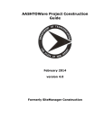
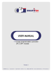
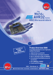
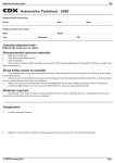
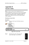
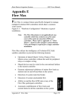
2-584-980-11(2)
Note
Tip
Do not connect a VCR, etc., between your TV and the player. If you pass
the player signals via the VCR, you may not receive a clear image on the
TV screen. If your TV has only one video input jack, connect the Unit to
this jack.
Run the cables into the hole marked with an “ ” in the illustration
*
above, so that you can bundle and fix the cables.
Notes
• Make sure that the pre-construction bracket is properly level, both
horizontally and vertically. Improper positioning may cause the
unit to fall, or may cause difficulty when you install the Unit.
• Make sure that more than 4 inches (10 cm) of space is available
behind the wall for installing the unit.
Custom Integrated
AV System
3
Place the AM loop antenna on the stud, and then fasten
the supplied screws to attach it. Raise the entire AM
antenna, and then insert its tab into the notch to set up
the AM loop antenna.
Take care to attach the AM loop antenna on the stud as far
away from the CDP-NW10, DVP-NW50, or other electrical
devices as possible (at least 1 foot (30 cm)).
4
After the wall construction is finished, cut the outline
along the inside edge of the pre-construction bracket.
Do not cut over or beyond the edge.
Before proceeding to step 4, make sure that all the necessary
cables can be run to the bracket location.
Connecting audio Equipment
Connections between the Unit and each of devices are made via
cables or cords coming through the wall.
The Unit can input sound from external audio equipment via the
audio connectors on the Unit. Connect the OUTPUT jacks (L/R)
of the audio equipment to the LINE IN (L/R) jacks of the Unit
using the proper audio cords (optional).
Installer’s manual
Connecting an IR IN/OUT
This manual is for installers only.
Contact your nearest installer for details on making
the required connections for the system network.
Connections between the Unit and each of devices are made via
cables or cords coming through the wall.
You can operate a component using the remote if the IR IN/OUT
terminal of the Unit and the component are connected. For
example, if you connect IR IN of the Unit and IR OUT of a TV,
you can operate the Unit with the remote by aiming it at the TV.
© 2005 Sony Corporation Printed in Korea
On placement
Precautions
Caution
Unauthorized substitutions may result in fire, electric shock,
causing die or serious injury.
Keep the following precautions in mind to prevent any accidents.
• Installment and settings other than that of specified
instructions may cause the unit to fall due to lack of strength of
the wall.
• Do not use screws other than the supplied screws for
installation.
• Do not install the unit following any procedure other than that
explained in this manual. Make sure to follow the procedure in
this manual closely.
• Do not disassemble the unit. This may cause a malfunction of
the unit or cause injury to you.
• Do not apply strong pressure on the unit after mounting it. The
unit may be damaged or fall, causing a injury to you.
• The Unit is designed for mounting only on the wall. You cannot
mount it on the ceiling or on the floor.
• Place the Unit in a location with adequate ventilation to
prevent heat build-up in the Unit.
• Do not place the Unit on a soft surface such as a rug.
• Do not place the Unit in a location near heat sources, or in a
place subject to direct sunlight, excessive dust, or mechanical
shock.
• Do not install the Unit in an inclined position. It is designed to
be operated in a horizontal position only.
• Keep the Unit and the discs away from equipment with strong
magnets, such as microwave ovens, or large loudspeakers.
• Do not install the unit in a humid location, such as in a
bathroom, or a place where moisture condensation may occur.
Install the Unit in a place where the environment falls within
the operating temperature 0˚C – 40˚C (32˚F – 104˚F).
• Do not step on or place heavy objects on the unit. The unit may
be damaged or fall, causing injury to you.
Note
Make sure that the size of the hole cut in the wall corresponds to the
specified size (height: 83/8 X 87/16 inches, 212.5 - 215 mm), (width:
83/16 X 81/4 inches, 207.5 - 210 mm). If the hole is too big to mount
the bracket, the Unit may fall and cause an accident.
5
If you connect IR OUT of the Unit and IR IN of a component,
such as a DVD Changer, you can operate the DVD Changer with
the remote (supplied with the DVD Changer) by aiming it at the
Unit.
Place the mounting bracket over the hole so that the preconstruction bracket and the mounting bracket match
across the wall. Then fasten the wall mounting bracket
screws carefully to fix the mounting bracket and preconstruction bracket so that they are level and align
perfectly.
Make sure the larger tab is mounted at the bottom.
On power sources
• The Unit is not disconnected from the AC power source as long
as it is connected to the wall outlet, even if the player itself has
been turned off.
• If you are not going to use the Unit for a long time, be sure to
disconnect the Unit from the wall outlet. To disconnect the AC
power cord, grasp the plug itself; never pull the cord.
Connecting an AC power unit
Larger tab
After connecting the Unit and the AC power unit using the
power supply cables, connect the AC power cord to the AC IN of
the AC power unit, then the other end of the AC power cord to
the wall outlet.
Unpacking
CDP-NW10/DVP-NW50 System
Network
Item
The diagram below illustrates an entire system network made up
with multiple Units.
CDP-NW10
DVP-NW50
CDP-NW10 Unit
1
–
DVP-NW50 Unit
–
1
Remote commander (remote)
(RM-ANU001 )
1
1
Wall mounting bracket
1
1
Wall stopper
4
4
TEMPLATE
1
1
Plug-in 4P terminal (for speakers)
1
3
Plug-in 5P terminal
(for AC power unit)
1
–
Plug-in 6P terminal
(for AC power unit)
–
1
Screws for fixing the Unit to
the wall mounting bracket (short)
4
4
Screws for wall stopper (long)
4
4
AM loop antenna (aerial)
1
1
R6 (size-AA) battery
2
2
User’s manual
1
1
Installer’s manual (this manual)
1
1
Note
The configuration shown below is for illustrative purpose only. It differs
from an actual system network.
KITCHEN
BEDROOM
CDP-NW10
INTERNET
GUEST ROOM
CDP-NW10
CDP-NW10
Hub
Router
Computer
LIVING ROOM
Front
Speaker
TV/Projector
Rear
Speaker
Front
Speaker
DVP-NW50
• Fasten the screws securely. Failure to fasten the screws or
incomplete tightening of the screws may cause the Unit to fall and
cause an accident.
• For mounting the bracket, use the supplied screws.
To mount the unit on the finished wall
Before installing the Unit into the wall, take steps to ensure your
safety and that of your surroundings, then check the following:
• The location of the power source to make sure that power supply cable
can reach from the Unit.
• The location of the speakers to make sure that speaker cords can be run
between the Unit and the speakers.
• The distance between the Unit and the AC power unit (up to 200 feet
(60 m)).
• The durability of the wall (The thickness of the wall must be between
1/2 to 3/4 inches. (13 mm to 19 mm)).
• There are no obstructions, such as an air, an electrical, or a water
conduit near the location where the Unit is installed.
• There is enough space (over 6 inches (15 cm)) inside the wall. If the
space available inside the wall is insufficient or does not have proper
ventilation, a malfunction of the Unit may occur due to heat build-up.
• Do not install the Unit where the Unit may get wet due to water or
other liquid. This may cause a malfunction of the Unit.
• Do not install the Unit in a place where moisture condensation may
cause a malfunction of the Unit.
1
Mark the location where the Unit is to be installed on the
wall using the supplied TEMPLATE (83/8 X 81/4 inches (212.5
mm X 207.5 mm)).
Make sure the mark is properly level, horizontally and
vertically.
2
Cut the outline along the mark, then carefully cut a clean
hole through the wall.
Notes
• Do not cut over or beyond the outline.
• Make sure that the size if the hole cut in the wall corresponds to the
specified size. If the hole is too big to mount the bracket, the Unit
may fall and cause an accident.
• Do not make a gap between the wall and the mounting bracket.
3
Rotate the stoppers to the inside of the frame, and then
place the mounting bracket over the hole.
Make sure the larger tab is mounted at the bottom.
4
Rotate the stoppers to the outside of the frame behind
the wall.
Installing brackets for new construction (before
wall construction is finished)
You may install a pre-construction bracket on the studs where the
unit will be installed. It is recommended that you use a preconstruction bracket when you install the unit in a house that is
still under construction. However, the pre-construction bracket is
only for the use of sub installation. You may not be able to use the
pre-construction bracket on the place where the wall and material
of the wall and pillar may be damaged or some other problems
may occur.
CD Changer
Center
Sub Woofer
Speaker
Installing the Unit
Notes
Rear
Speaker
Example of the DVP-NW50 system network
Connecting a computer
Connect each Unit and a computer using an Ethernet cable
(100Base-TX, optional.) For details on the connection, refer to
“Hooking up the sysytem” on this manual and the instruction
manual supplied with your router or hub.
Note
The following items are included in the Pre-construction bracket kit (WSBKT1).
• Pre-construction bracket (1)
• Wings (2)
• AM Antenna (1)
• Screws for the AM Antenna (2)
• Manual (1)
1
5
Fasten the wall mounting bracket screws carefully so that
the wall mounting bracket is level.
Insert the two wings into the tabs of the pre-construction
bracket.
Connecting a TV (DVP-NW50 only)
Connections between the Unit and each of devices are made via
cables or cords coming through the wall.
Connect the Unit to a TV or a projector using the VIDEO cord.
Select one of the ways of connection methods shown below,
according to the input jack on your TV.
Larger tab
Wing
2
Place the pre-construction bracket on the studs, and then
fasten the screws (not supplied) to attach the preconstruction bracket.
Notes
*
• Fasten the screws securely. Failure to fasten the screws or
incomplete tightening of the screws may cause the Unit to fall and
cause an accident.
• For mounting the bracket, use the supplied screws.
Hooking up the system
An optional AC power unit (AC-NW10/AC-NW50) is required
to hook up the system.
CDP-NW10
Speaker hookup
Before connecting each of speaker cables to the Unit, you must
connect them to the supplied speaker connector. See
“Connecting speaker cables to the speaker connector.”
7 SPEAKERS (CDP-NW10)
Connects speakers in a room using a speaker cable.
8 SPEAKERS (DVP-NW50)
a) SUB WOOFER/CENTER
Connects a sub woofer and a center speaker using a speaker
cable .
b) SUR R/SUR L
Connects surround speakers using speaker cables.
c) FRONT R/FRONT L
Connects front speakers using speaker cables.
Mounting the Unit into the wall
Before connecting the cords and cables, make sure of the
following:
• Cords and cables to be connected to the Unit reach to the Unit
location.
• Turn off all of the components before making any connections.
• Do not connect the AC power cords until all of the connections
are completed.
• Be sure to make connections firmly to avoid hum and noise.
1
2
Other hookup
9 DC IN for the CDP-NW10/
0 DC IN for the DVP-NW50
Connects the DC IN connector using the power supply cables
inserted to connect the AC power unit and a Unit.
DVP-NW50
Connect each of the cords and cables to the corresponding
connectors.
See “Hooking up the system” for details on the connections.
Make sure each of the cords and cables is connected securely.
When you have finished making all of the connections,
insert the bottom of the Unit onto the mounting bracket
first, then push the top of the Unit onto the bracket.
If the Unit does not slide into the mounting bracket, remove
the Unit from the bracket, then loosen or fasten the screws to
adjust the mounting bracket position.
qa DC OUT for the CDP-NW10/
qs DC OUT for the DVP-NW50
Connects the DC OUT connector using the power supply cables
inserted to connect the AC power unit and a Unit.
It is recommended that you test the system connection before
proceeding to step 3.
3
Fix the Unit onto the wall with the screws at the four
points as shown below.
Speaker connector for CDP-NW10/DVP-NW50
Be sure to match the speaker cables to the appropriate terminal
on the connector: + to + and – to –. If a cable is reversed, the
sound may be distorted. Use an ordinary screwdriver to fasten
the screws.
4
Press the side panels in at both sides of the Unit until they
click.
CDP-NW10
AC-NW10/AC-NW50 (rear) (optional)
To the
Then, to the SPEAKER OUT
Speaker + (R)/ – (R)
A/B
7
Speaker + (L)/– (L)
C/D
7
DVP-NW50
Three speaker connectors are required for the DVP-NW50 since it
produces 5.1ch surround sound.
Antenna hookup
You can tune in AM/FM stations using the Unit.
1 ANTENNA (AM/FM)
Connects the AM loop antenna to the AM terminal.
Connects the FM loop antenna to the FM 75 ohm COAXIAL
terminal.
Network hookup
You can connect Units to other Units or computers via a router
or a hub.
Connect the
To the
Then, to the SPEAKER OUT
Sub woofer +/Sub woofer –
A/B
8 a)
Center speaker + / –
C/D
8 a)
Surround speaker + (R)/ – (R)
A/B
8 b)
Surround speaker + (L)/– (L)
C/D
8 b)
Front speaker + (R)/ – (R)
A/B
8 c)
Front speaker + (L)/– (L)
C/D
8 c)
Audio component hookup
You can listen to the sound from external audio equipment via
the Unit.
3 LINE (Analog) IN (L/R)
Connects the OUTPUT jacks (L/R) of the audio equipment to
the LINE IN (L/R) jacks of the Unit using audio cables (not
supplied).
IR IN/OUT hookup
You can control components with the remote in a wider range
by connecting the Unit and the component to IR IN/OUT.
4 IR IN
Connect IR IN of the Unit and IR OUT of a component, such as
a TV so that you can operate the Unit with the remote by
aiming it at the TV.
4 Remove the mounting bracket from the pre-construction
bracket or the wall.
Connecting the AC power Unit
1
Black
A
9 / qa
14V
Yellow
B
9 / qa
GND
Blue
C
9 / qa
29.5V
Red
D
9 / qa
2
3
4
5
A B
C D
4 IR OUT
Connect IR OUT of the Unit and IR IN of a component, such as
a CD Changer, so that you can operate the DVD Changer with
the remote by aiming it at the Unit.
SP.SIZE
(speaker size)
FRONT
CENTER
SURROUND
S.WOOFER
Chapter 8
SP.DISTANCE
(speaker distance)
FRONT
CENTER
SURROUND
LEVEL (DVD-NW50 only) S.WOOFER
FRONT
CENTER
SURROUND L
SURROUND R
5 VIDEO OUT (DVP-NW50)
Connects the video input of a TV or a projector and the VIDEO
OUT jack of the Unit using a video cable.
6 S VIDEO OUT (DVP-NW50)
Connects the S VIDEO input of a TV or a projector and the S
VIDEO OUT jack of the Unit using a S VIDEO cable.
OFF
DRC
(DVD-NW50 only)
OFF
TEST TONE
(DVD-NW50 only)
OFF
VOL.PRESET
(volume preset)
OFF
VOL.LEVEL
(volume level)
OFF
IR ROUTE
Both
Chapter 1
INTERCOM PRIVACY
OFF
Chapter 6
MONITOR PRIVACY
OFF
PARTY PRIVACY
OFF
Specifications
Power requirements: AC 120 V, 60 Hz
DC Power consumption:
CDP-NW10: DC 29.5 V/1 A, DC 14 V/1.5 A
DVP-NW50: DC 29.5 V/1 A, DC 29.5 V/1 A,
DC 14 V/1.5 A
AC Power consumption:
AC-NW10: AC 120 V/3.6 A
AC-NW50: AC 120 V/2.1 A
DC output:
AC-NW10: DC 29.5 V, DC 14 V for output 1
DC 29.5 V, DC 14 V for output 2
DC 29.5 V, DC 14 V for output 3
Make sure all the power supply cables are inserted into
the proper DC IN/OUT connector.
AC-NW50: DC 29.5 V for output 1
DC 29.5 V for output 2
Plug the DC IN/OUT connector into the DC OUT of the AC
power unit with the screw side facing up.
DC 14 V for output 3
Plug the AC power cord into AC IN of the AC power Unit.
Operating temperature:
0˚C – 40˚C (32˚F – 104˚F)
Plug the other end of the AC power cord into the wall
outlet.
Storage temperature:
When you have completed all the required settings, turn
on the AC power unit.
-20˚C – 60˚C (-4˚F – 140˚F)
Dimensions:
CDP-NW10/DVP-NW50:
230 ✕ 266 ✕ 104 mm
(9 1/8 ✕ 10 1/2 ✕ 4 1/8 inches)
AC-NW10/NW50:
Setting up the Units
244 ✕ 316 ✕ 72 mm
(9 5/8 ✕ 12 1/2 ✕ 2 7/8 inches)
Connect the
(cable color) To the
Then, to the DC IN/OUT
GND
Black
0 / qs
14V
Yellow
a
b
0 / qs
GND
Brown
c
0 / qs
ND
Orange
d
0 / qs
16V
Blue
e
0 / qs
29.5
Red
f
0 / qs
Note
Do not connect a VCR, etc., between your TV and the player. If you pass
the player signals via the VCR, you may not receive a clear image on a TV
screen. If your TV has only one video input jack, connect the player to this
jack.
0 dB
0 dB
0 dB
0 dB
0 dB
DIMMER
(CVD-NW10 only)
DVP-NW50
Video component hookup
Select one of the connection methods shown below, according
to the input jack on your TV monitor.
10 ft (3m)
10 ft (3m)
10 ft (3m)
3 Remove all the cables and the cords from the Unit and the
AC power unit.
CDP-NW10
GND
Chapter No.
2 Perform steps from 4 to 1 in “Mounting the Unit into the
wall.”
DC IN connector for the CDP-NW10/DVP-NW50
Use Sony’s connecting cables for the required connections of the
Unit and AC power unit.
Then, to the DC IN/OUT
Default value
1 Turn off the AC power unit, then disconnect the AC power
cord from the wall outlet.
After completing all the connections, make sure there are no misconnections or improper wiring before plugging the Unit into the
wall outlet. Improper wiring or mis-connections may cause the
Unit to be damaged.
(cable color) To the
Item
To uninstall the Unit
Note
Connect the
Reference
Dimensions
You can connect up to four Units (CDP-NW10), or one Unit
(DVP-NW50) to an AC power unit.
Before connecting the AC power cord of the AC power unit to a
wall outlet, connect all parts of the system to the Unit.
2 ETHERNET
Connects the Units to a router or a hub using a Ethernet cable.
• Naming the Unit.
• Setting the time
Note
AC-NW10 AC power unit for CDP-NW10 (front) (optional)
Connect the
You must also customize the following settings. Refer to the
“Setting up the Units” in Chapter 1 of the User’s Manual.
• IP address
The table shown below describes the default setting of items on
the User setup Menu. To change these items, refer to each chapter
in the User’s manual indicated below.
Connecting speaker cables or power supply
cables to the connectors
AC-NW50 AC power unit for DVP-NW50 (front) (optional)
• Under normal conditions, the batteries should last for about six months.
When the remote no longer operates the player, replace both batteries
with new ones.
• Do not leave the remote in an extremely hot or a humid place.
• Do not drop any foreign object into the remote casing, particularly
when replacing the batteries.
• Do not use a new battery with an old one.
• Do not expose the IR sensor to direct sunlight or lighting equipment.
Doing so may cause a malfunction.
• If you do not intend to use the remote for an extended period of time,
remove the batteries to avoid possible damage from battery leakage and
corrosion.
Default value of the User setup Menu
qd POWER
Turns the AC power units on.
qf AC IN
Plugs the AC power cord to the AC IN of the AC power unit.
You must connect the speaker cables from each of the speakers to
the proper speaker connector, then plug it into the SPEAKER
OUT terminal of the Unit. Also you must connect the power
supply cables to the DC IN connector, then plug it into the DC
OUT terminal of the AC power unit.
Notes
a b c d e f
Mass:
CDP-NW10: 2.5 kg (5 lbs 8 oz.)
DVP-NW50: 2.7 kg (5 lbs 15 oz.)
Preparing the remote
Insert two R06 (size-AA) batteries into the battery compartment
with the + and – correctly oriented to the markings. When using
the remote, point it at the IR sensor on the Unit.
AC-NW10: 2.7 kg (without AC code)
AC-NW50: 2.5 kg (without AC code)
Design and specifications are subject to change without notice.