1
CONNECT WITH RELIABILITY
Syncdrive Plus
Communications Software
User’s Manual
QUATECH, INC.
662 Wolf Ledges Parkway
Akron, Ohio 44311
Toll free: 1-800-553-1170
TEL: (330) 434-3154
FAX: (330) 434-1409
http://www.quatech.com
Syncdrive Plus
User’s Manual P/N: 940-0184-100
Copyright
Copyright © 1984 - 2003, Quatech, Inc. All rights are reserved. The
information contained in this document cannot be reproduced in any form
without the written consent of Quatech, Inc. Any software programs that
might accompany this document can be used only in accordance with any
license agreement(s) between the purchaser and Quatech, Inc. Quatech,
Inc. reserves the right to change this documentation or the product to
which it refers at any time and without notice.
Trademarks
QUATECH® is a registered trademarks of Quatech, Inc. IBM PC™,
PC-AT™, PS/2™, OS/2™, and Micro Channel™ are trademarks of
International Business Machines Corporation. Windows™ is a trademark
of Microsoft Corporation. Other product and brand names listed in this
manual may be trademarks of their respective owners.
Disclaimer
The information in this manual is believed to be accurate and reliable at
the time of posting. Notwithstanding the foregoing, Quatech assumes no
responsibility for any damage or loss resulting from the use of this
manual, and expressly disclaims any liability or damages for loss of data,
loss of use, and property damage of any kind, direct, incidental or
consequential, in regard to or arising out of the performance or form of
the materials presented herein or in any software program(s) that may
accompany this document.
Changes or modifications to this device not explicitly approved by
Quatech will void the user's authority to operate this device.
Feedback
Quatech, Inc. encourages and appreciates feedback concerning this
document. Please send any written comments to the Technical Support
department at the address listed on the cover page of this manual.
Quatech Syncdrive Plus User’s Manual
Table of contents
Table of contents
Introduction ----------------------------------------------------------------------------------------------------------------------- 1
System Requirements ---------------------------------------------------------------------------------------------------- 1
Installing Syncdrive plus ------------------------------------------------------------------------------------------------ 2
Synchronous communication with Syncdrive Plus -------------------------------------------------------------------- 6
Understanding BIT-synchronous formatting ---------------------------------------------------------------------- 6
Operational overview----------------------------------------------------------------------------------------------------------- 7
Data handling --------------------------------------------------------------------------------------------------------------- 7
Transmitting frames------------------------------------------------------------------------------------------------- 7
Receiving frames------------------------------------------------------------------------------------------------------ 8
Clocking parameters ------------------------------------------------------------------------------------------------------ 8
Include file structure------------------------------------------------------------------------------------------------------ 9
Operating under Windows 2000/XP ---------------------------------------------------------------------------------- 9
Building Syncdrive Plus applications -------------------------------------------------------------------------- 9
Terminating applications ------------------------------------------------------------------------------------------ 9
Tips and Techniques------------------------------------------------------------------------------------------------- 9
Syncdrive Plus data structures --------------------------------------------------------------------------------------------10
Syncdrive Plus application programming interface------------------------------------------------------------------16
Calling convention --------------------------------------------------------------------------------------------------------16
Return values --------------------------------------------------------------------------------------------------------------16
Examples --------------------------------------------------------------------------------------------------------------------17
Command reference ------------------------------------------------------------------------------------------------------17
Using example programs-----------------------------------------------------------------------------------------------------29
Source code------------------------------------------------------------------------------------------------------------------29
Executable files ------------------------------------------------------------------------------------------------------------29
Descriptions of example programs -----------------------------------------------------------------------------------29
LPBCKBI2K ----------------------------------------------------------------------------------------------------------29
FDBCKBI2K ----------------------------------------------------------------------------------------------------------29
SENDBI2K ------------------------------------------------------------------------------------------------------------29
RECBI2K---------------------------------------------------------------------------------------------------------------30
THREADRX2K -------------------------------------------------------------------------------------------------------30
THREADTX2K -------------------------------------------------------------------------------------------------------30
Crossover cable -------------------------------------------------------------------------------------------------------30
Troubleshooting-----------------------------------------------------------------------------------------------------------------31
Verify that the hardware is configured properly ----------------------------------------------------------------31
Check the Syncdrive Plus configuration ---------------------------------------------------------------------------31
Check the clock sourcing------------------------------------------------------------------------------------------------31
Know the speed limits ---------------------------------------------------------------------------------------------------31
Error codes -----------------------------------------------------------------------------------------------------------------------32
Appendix A -----------------------------------------------------------------------------------------------------------------------33
Definitions ------------------------------------------------------------------------------------------------------------------33
Rev 01 (2/6/2003)
Page i
Quatech Syncdrive Plus User’s Manual
Table of contents
Table of figures
Figure 1 - Found new hardware prompt .................................................................................................... 2
Figure 2 - Welcome screen .......................................................................................................................... 2
Figure 3 - Install Hardware Device Drivers screen................................................................................... 3
Figure 4 - Locate Driver Files screen ......................................................................................................... 3
Figure 5 - Insert installation disk prompt ................................................................................................. 4
Figure 6 - Locate File screen....................................................................................................................... 4
Figure 7 - Driver Files Search Results screen ........................................................................................... 5
Figure 8 - Completing the Found New Hardware Wizard screen ............................................................ 5
Figure 9 - Syncdrive Plus bit-synchronous frame format ......................................................................... 6
Figure 10 - RS-232 Crossover cable pinouts ............................................................................................ 30
Figure 11 - RS-422/485 Crossover cable pinouts ..................................................................................... 30
Rev 01 (2/6/2003)
Page ii
Quatech Syncdrive Plus User’s Manual
Introduction
Introduction
Note: For on-line technical
support, see Quatech’s Web site:
http://www.quatech.com/technical
.htm
Syncdrive Plus is a synchronous communications software driver
package that helps users of Quatech synchronous communication
hardware to develop their application software.
The Syncdrive Plus driver package includes these features:
!
Multiple communication channels using multiple MPA-series
adapters
!
!
!
Support for bit-synchronous (SDLC, HDLC) communications
User-control of most communication parameters
Relieves programmers of the burden of directly programming the
synchronous communications hardware
User can change or upgrade synchronous communication
hardware with minimal modifications to the application software
!
!
Support for all Quatech MPA-series PCI bus and PCMCIA
adapters:
*
*
MPAP-100: Multi-protocol RS-232 synchronous serial card
*
MPAC-100: Single port RS-232 synchronous board.
MPAP-200/300: Multi-protocol RS-422/485 synchronous serial
card
! Versions for Windows 2000 and Windows XP
Written specifically for use with C, Syncdrive Plus is also compatible
with other languages that support C-type subroutine interfaces.
System Requirements
The system requirements are as follows:
Note: See Quatech’s Internet
site for the latest drivers and
updates:
http://www.quatech.com/.
Rev 01 (2/6/2003)
! PC running either Windows 2000 or Windows XP
! Available PCI slot or PC Card slot
We recommend that you install the latest service packs.
All other requirements are the same as for the respective operating
systems.
Page 1
Quatech Syncdrive Plus User’s Manual
Introduction
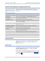
Installing Syncdrive plus
Follow this procedure to install your Quatech Syncdrive Plus
synchronous communication software.
Step
Procedure
Description
! Step 1
Insert the Quatech installation CD-ROM
into your CD-ROM drive.
This is the CD that shipped with the
MPAX-XXX adapter.
! Step 2
Insert the MPAX-XXX adapter into any
available PC Card socket.
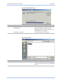
The Found New Hardware prompt
displays briefly, followed by the Found
New Hardware Wizard’s Welcome screen.
Figure 1 - Found new hardware prompt
Figure 2 - Welcome screen
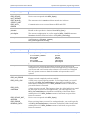
Step
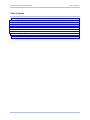
! Step 3
Procedure
Description
Press Next to continue.
The Install Hardware Device Drivers
screen displays.
Rev 01 (2/6/2003)
Page 2
Quatech Syncdrive Plus User’s Manual
Introduction
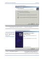
Figure 3 - Install Hardware Device Drivers screen
Step
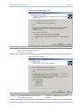
! Step 4
Procedure
Description
Select the Search for a suitable driver for
my device (recommended) option.
Press Next to continue.
The Locate Driver Files screen displays.
Figure 4 - Locate Driver Files screen
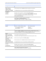
Step
! Step 5
Procedure
Description
Select the Specify a location option.
Press Next to continue.
The Insert installation disk prompt
displays.
Rev 01 (2/6/2003)
Page 3
Quatech Syncdrive Plus User’s Manual
Introduction
Figure 5 - Insert installation disk prompt
Step
! Step 6
Procedure
Description
Browse to the correct drive location on your The complete path is E:\Synchronous
CD-ROM drive.
Adapters\Software\Windows 2000,
XP\Syncdrive Plus. Replace E: with your
CD-ROM drive designation.
Click OK to continue.
The Locate File screen displays.
Figure 6 - Locate File screen
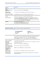
Step
! Step 7
Procedure
Description
Select the Quainf.inf file and click Open.
The Driver Files Search Results screen
displays, showing the path to the Quainf.inf
driver.
Rev 01 (2/6/2003)
Page 4
Quatech Syncdrive Plus User’s Manual
Introduction
Figure 7 - Driver Files Search Results screen
Step
! Step 8
Procedure
Description
Make sure the directory path ends at the
Quainf.inf file. Click Next to continue.
The Completing the Found New Hardware
Wizard screen displays.
Figure 8 - Completing the Found New Hardware Wizard screen
Note: You can find your
Syncdrive Plus adapter listed
in
the
Windows
Device
Manager under Synchronous
Communication
Step
! Step 9
Procedure
Description
Click Finish to continue.
The Installation Wizard completes the
installation of the Syncdrive Plus driver.
Rev 01 (2/6/2003)
Page 5
Quatech Syncdrive Plus User’s Manual
Synchronous Communication with Syncdrive Plus
Synchronous communication with Syncdrive Plus
Note: Syncdrive Plus uses
synchronous
communication
for faster data transfer rates
with less overhead.
Most data communications in personal computers is handled
asynchronously using standard communication ports. Asynchronous
communication transfers data one character at a time with
significant overhead due to the addition of the start and stop bits
required for each character. These additions can decrease the rate of
data transfer by 20% or more.
In contrast, synchronous communication transfers data in a format
referred to as a frame. Each frame consists of a block of data plus a
fixed amount of overhead from the insertion of control, synchronization,
and error detection characters. Since the amount of overhead is
independent of the data block size, the percentage of the total
transfer time devoted to the frame overhead diminishes as the size of
the data block increases.
Synchronous communication is further divided into bit-synchronous
and byte-synchronous transfers. Bit-synchronous transfers treat the
data block as a series of data bits with no specific character
boundaries. Byte-synchronous transfers treat the data block as a
series of fixed-length characters.
The first release of Syncdrive Plus transfers data in bit-synchronous
mode only. The bit-synchronous mode can be used to implement such
protocols as SDLC or HDLC. Syncdrive Plus does not implement any
specific protocol itself, but supports most protocols implemented by
the application software. Future releases of Syncdrive Plus will add
support for byte-synchronous modes such as BISYNC.
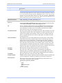
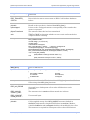
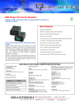
Understanding BIT-synchronous formatting
Syncdrive's bit-synchronous mode generates a frame formatted
according to the scheme shown below.
Figure 9 - Syncdrive Plus bit-synchronous frame format
flag
data
CRC
flag
The hardware uses the frame's start flag and end flag characters for
synchronization purposes. When the application transmits a block of
data, Syncdrive Plus automatically appends these flag characters to
the frame. When receiving a frame, the driver automatically removes
these flag characters from the frame before returning it to the
application.
Syncdrive Plus uses the frame's CRC bytes for error detection
purposes. When transmitting a block of data, it automatically
generates and transmits the CRC after it sends all of the data. When
receiving a frame, Syncdrive Plus automatically checks the CRC to
determine if the frame was corrupted. If a CRC error occurs,
Syncdrive Plus returns an error code (see MPA_GetData() return
values).
Rev 01 (2/6/2003)
Page 6
Quatech Syncdrive Plus User’s Manual
Operational overview
Operational overview
Data handling
The Syncdrive Plus driver simplifies application development.
Applications simply read and write frames as they would files
without any worry about buffer management, interrupts, or register
handling.
Once a handle is opened to the driver, the application can write as
many frames as desired if the handle was opened with overlapped
I/O. Syncdrive Plus queues the frames in the order in which they
were received and sends them out one at a time. The number of
frames that can be queued is limited only by system resources.
However, if the handle is opened without overlapped I/O, only a single
frame can be transmitted at one time. Control returns to the
application when the transfer is completed.
Note: The application can loop
on MPA_GetFrameCount() until
a frame is received. Once the
application receives a frame, it
calls MPA_GetFrameSize() to
determine the frame’s size so
that it can allocate an
appropriately sized buffer.
The driver can also queue frame buffers for receive if non-overlapped
I/O is specified. The buffers are filled as frames arrive. Alternately, if
the application did not queue read buffers, buffers in the driver can
store received frames until the application requests them. The size
and quantity of these driver receive buffers are dynamically
configurable.
If non-overlapped I/O is specified, only one frame can be read at a
time. If a frame has already been received, it is copied into the
application buffer immediately; otherwise, the driver waits until it
receives a complete frame before returning control to the application.
Transmitting frames
Queued transmit frames use Windows’ built-in I/O request queuing,
which stores data in a system buffer until it can be transmitted. The
application can obtain transfer status by using MPA_GetTransferStatus().
However, transmit frames are not queued for non-overlapped I/O. In
this case, the application waits until the frame has been transferred
before regaining control.
The Quatech board has a 1-KB transmit FIFO to supplement the 4byte transmit FIFO in the Zilog ESCC chip. If it receives an end-offrame (EOF) or the transmitter is not busy, the driver immediately
transfers as much data as possible into the transmit FIFOs. If the
frame is smaller than the FIFO size, then the transmit code waits
until the frame is transmitted completely before starting the next
frame. If the frame is larger than the FIFO depth, the driver waits for
an interrupt that indicates that the transmit FIFO has drained to
half capacity. At this point, the transmit code fills the transmit FIFO
up to its capacity. This process repeats until the entire frame buffer
has been transferred into the FIFOs. When the driver receives an
EOF interrupt indicating that the frame has been transmitted
completely, it starts the next frame (if there is one queued).
Rev 01 (2/6/2003)
Page 7
Quatech Syncdrive Plus User’s Manual
Operational overview
Receiving frames
The receive code has driver-allocated buffers that receive frames
without needing a user-supplied buffer. This allows the application to
allocate buffers as frames arrive.
Note: Typically, you would use
this approach for known frame
sizes and arrival times.
A typical approach is to call MPA_GetFrameCount() until frame(s)
arrive. The application then uses MPA_GetFrameSize() to allocate the
buffer size and retrieves the frame using MPA_GetData().
Alternatively, the application can keep read buffers queued in
anticipation of incoming frames.
The receive logic works in a similar fashion to the transmit logic. The
Quatech board has a 1-KB receive FIFO to supplement the 8-byte
receive FIFO in the Zilog ESCC chip. If it receives a frame is that is
smaller than half of the receive FIFO depth, the receive code simply
acknowledges the EOF interrupt and transfers the frame either into
an internal buffer if there is no queued read buffer, or directly into
the user's read buffer if there is one. For frames larger than halfFIFO size, the receive code generates interrupts when the half-FIFO
depth is reached. The driver then drains the receive FIFO by filling
either the internal buffer or the user's buffer. This process repeats
until the EOF is reached.
Note: There are no internal
buffers for transmit because
queued transmit buffers use
the system buffers.
The receive buffers are configurable using MPA_SetConfig() as detailed
in the API (see Syncdrive Plus application programming interface)
and Structure (see Syncdrive Plus data structures) sections. The
driver allocates these buffers when the device is opened. Be sure to
take care to minimize requirements because the driver uses nonpaged system memory, which is scarce after boot-up.
The maximum number of internal receive buffers matches the
maximum number of frames that can be queued in the ESCC, which
is 10 frames. The ESCC has a status FIFO that queues the frame
lengths, so the frames do not have to be serviced immediately. The
maximum internal buffer length matches the depth of the internal
ESCC counters, 16 K. Once again, transmit buffers are only limited
by system resources.
Clocking parameters
The API supports many different clocking configurations. It is up to
the application to configure valid combinations. The application can
control the following:
!
Transmit clock source
!
!
!
Receive clock source
Output of TRxC pin
DPLL clock source and mode if DPLL used
!
Baud rate of the baud rate generator (BRG), if BRG is used
Clocking can originate from two sources within the Quatech board:
1. Baud rate generator (BRG)
2. Digital phase locked loop (DPLL)
Rev 01 (2/6/2003)
Page 8
Quatech Syncdrive Plus User’s Manual
Operational overview
The BRG is a variable-rate clocking mechanism used with external
clock pins. The DPLL is used to encode the clocking signal within the
data stream, eliminating the need for an external clock pin. The
DPLL requires a clock and can either acquire it from the BRG or
externally through the RTxC pin.
Include file structure
QuaDLL.h – Provides function prototypes for Syncdrive Plus API
functions.
QuaDef.h – Defines structures that are used with Syncdrive Plus API
calls.
Operating under Windows 2000/XP
Building Syncdrive Plus applications
Link the application's object modules with the Syncdrive Plus API
import library file QuaDLL.LIB. The file can be found in the
\Synchronous Adapters\Software\Windows 2000, XP\Syncdrive Plus
\Examples directory of the Quatech CD-ROM.
Ensure that the Windows XP/2K device driver has been installed
properly on the system.
You can find all the required Syncdrive Plus include files in the
\Synchronous Adapters\Software\Windows 2000, XP\Syncdrive
Plus\Examples directory of the Quatech CD-ROM.
Syncdrive Plus applications must include the QuaDLL.h file.
Applications must use the MPADLL_API calling convention, defined in
the QuaDLL.h include file, in order to access the Windows DLL.
Terminating applications
Applications should ensure that any allocated memory is freed before
terminating.
Because applications can terminate unexpectedly due to bugs or
operator intervention, termination procedures should be called in exit
handler functions.
Tips and Techniques
Note: Syncdrive
structures must
aligned.
Rev 01 (2/6/2003)
Plus data
be 8-byte-
The following is an outline of the basic steps that an application must
take to transmit or receive data frames using Syncdrive Plus.
1.
2.
3.
4.
5.
6.
7.
Allocate data structures.
Configure the channel.
Register buffer queues (optional).
Transmit or receive data.
Free buffer queues (if used).
Release the channel.
Deallocate data structures.
Page 9
Quatech Syncdrive Plus User’s Manual
Syncdrive Plus data structures
Syncdrive Plus data structures
Note: This design ensures that
the application uses the same
header file as the driver files
and helps to minimize difficult
memory overwrite debugging.
This section describes the structures that Syncdrive Plus uses with
API calls. Every structure passed to the API needs its structLen
member filled out with the structure's length in bytes. This is true
even if the structure is used to retrieve information from the driver.
MPA_CONFIG
Handles device configuration
Syntax:
typedef struct tagMPA_CONFIG
{
ULONG
structLen;
union
{
struct
{
// Set the following bits to indicate which parameter(s) are to be set.
// Parameter value(s) with corresponding bits set to zero are not
// changed.
// Tx does not require buffers since pending I/O requests provide buffers.
UCHAR
FrameBufferSizeRx
: 1;
UCHAR
NumFrameBuffersRx
: 1;
UCHAR
BaudRate
: 1;
UCHAR
ClockRate
: 1;
UCHAR
ClockMode
: 1;
UCHAR
InternalLoopback
: 1;
UCHAR
RxClockSource
: 1;
UCHAR
TxClockSource
: 1;
UCHAR
TRXCOutput
: 1;
UCHAR
Encoding
: 1;
UCHAR
DPLLClockSource
: 1;
UCHAR
DPLLMode
: 1;
UCHAR
AutoRTSDeact
: 1;
UCHAR
CRCPreset
: 1;
UCHAR
IdleLineControl
: 1;
ULONG
pad
: (8*sizeof(ULONG) - 13);
} bits;
ULONG all; // Used to clear/set all bits at once.
} set;
ULONG
FrameBufferSizeRx;
// In bytes.
ULONG
NumFrameBuffersRx;
ULONG
BaudRate;
ULONG
ClockRate;
ULONG
ClockMode;
BOOLEAN
InternalLoopback;
CLOCK_SOURCE
RxClockSource;
CLOCK_SOURCE
TxClockSource;
TRXC_OUTPUT
TRXCOutput;
ENCODING
Encoding;
DPLL_CLOCK_SOURCE DPLL ClockSource;
DPLL_MODE
DPLLMode;
BOOLEAN
AutoRTSDeact;
BOOLEAN
CRCPreset;
IDLE_LINE_CONTROL
IdleLineControl;
} MPA_CONFIG, *PMPA_CONFIG;
Rev 01 (2/6/2003)
Page 10
Quatech Syncdrive Plus User’s Manual
MPA_CONFIG
Description:
Syncdrive Plus data structures
Continued
Used to set or get device configuration(s).
Note: When configuring baud rate, be sure to remember to set both the clock rate
and the clock mode. The driver needs to know the oscillator frequency in order to
run at the baud rate specified. Because FM DPLL requires a clock rate 16 times
the data rate, the clock mode will be 16 in this case. Similarly, NRZI DPLL
requires a clock rate 32 times the data rate. Notice that clock mode acts as a
.
divisor and results in a lower maximum data rate.
API Functions Used:
Parameters:
structLen
set
FrameBufferSizeRx
NumFrameBuffers
BaudRate
ClockRate
ClockMode
InternalLoopback
RxClockSource
MPA_SetConfig() and MPA_GetConfig() only.
Length of the MPA_CONFIG structure in bytes. Should be filled in before
calling MPA_GetConfig() or MPA_SetConfig() functions.
Union composed of set structure and a ULONG all. Bits in set structure
are set to tell the driver the corresponding value is valid and should be
set in hardware. Use all to clear or set all bits simultaneously. Pad is
reserved and is only used to align the structure.
The size of each of the receive buffer(s) in bytes. This should be set to the
largest frame expected. The value should be as small as possible since it
requires non-paged system memory. This value only changes when the
device is opened. For the new values to take effect, you must close and
re-open the device.
The number of receive frame buffers for use by the driver. This setting
should be based on how quickly frames will be read from the driver. If
frame sizes are large, infrequent, or frame servicing will be handled as
frames arrive, then this value can be small. Back-to-back small frames
that cannot be serviced as they arrive would require a larger value. The
value should be as small as possible since it requires non-paged system
memory. This value only changes when the device is opened. For the new
values to take effect, you must close and re-open the device.
The baud rate in baud. Valid ranges are 1 to 1/6 of clock rate.
The clock rate in Hz. The clock rate is determined by the Quatech
hardware. Factory standard configuration is 9.8304 MHz. This value
may be different if you are using custom-configured Quatech hardware.
The clock mode rate. Can be X1, X16, X32, or X64.
TRUE to enable internal loopback. Internal loopback allows transmit and
receive testing from a single card without any external connections.
The source of the receive clock. Use the following enumeration to set
clock source. Any other value is invalid.
typedef enum tagCLOCK_SOURCE
{
RTXC,
TRXC,
BAUD_RATE_GEN,
DPLL
} CLOCK_SOURCE;
Rev 01 (2/6/2003)
Page 11
Quatech Syncdrive Plus User’s Manual
MPA_CONFIG
Parameters, cont.:
TxClockSource
Syncdrive Plus data structures
Continued
The source of the transmit clock. Use the following enumeration to set
clock source. Any other value is invalid.
typedef enum tagCLOCK_SOURCE
{
RTXC,
TRXC,
BAUD_RATE_GEN,
DPLL
} CLOCK_SOURCE;
TRXCOutput
Selection for what should be output the TRxC pin. Use the following
enumeration to set TRxC source. Any other value is invalid.
typedef enum tagTRXC_OUTPUT
{
CRYSTAL_OUT,
TX_CLOCK,
BAUD_RATE_GEN_OUT,
DPLL_OUT
} TRXC_OUTPUT;
Encoding
Encoding method for both transmit and receive. Use the following
enumeration to set encoding method. Any other value is invalid.
typedef enum tagENCODING
{
NRZ,
NRZI,
FM1,
FM0
} ENCODING;
DPLLClockSource
The source for the DPLL clock. This is required if DPLL is used. Use the
following enumeration to set DPLL clock source. Any other value is invalid.
typedef enum tagDPLL_CLOCK_SOURCE
{
DPLL_SRC_BAUD_RATE_GEN,
DPLL_SRC_RTXC
} DPLL_CLOCK_SOURCE;
DPLLMode
The DPLL mode. This is required if DPLL is used. Use the following
enumeration to set DPLL mode. Any other value is invalid.
typedef enum tagDPLL_MODE
{
DPLL_MODE_NRZI,
DPLL_MODE_FM
} DPLL_MODE;
AutoRTSDeact
CRCPreset
IdleLineControl
TRUE to select automatic RTS deactivation.
The preset value (either 0 or 1) to which the receive CRC checker and
transmit CRC generator should be set.
Specifies what should be transmitted on an idle line. The choices are
either to send all ones or the flag character (usually 7Eh for SDLC).
Sending all zeros is not supported on the ESCC chip. Use the following
enumeration to set idle line control. Any other value is invalid.
typedef enum tagIDLE_LINE_CONTROL
{
IDLE_LINE_FLAGS,
IDLE_LINE_ONES // ESCC doesn't support sending continuous 0s.
} IDLE_LINE_CONTROL;
Rev 01 (2/6/2003)
Page 12
Quatech Syncdrive Plus User’s Manual
Syncdrive Plus data structures
MPA_DRIVER_VERSION
Used to get driver version
Syntax:
typedef struct tagMPA_DRIVER_VERSION
{
ULONG
structLen;
// Driver version is in format major.minor.
UCHAR
major;
UCHAR
minor;
} MPA_DRIVER_VERSION, *PMPA_DRIVER_VERSION;
Description:
Structure for retrieving driver version. Driver version is in format
major.minor.
API Functions Used:
MPA_GetDriverVersion() only.
Parameters:
structLen
Length of the MPA_DRIVER_VERSION structure in bytes. Should be
filled in before calling MPA_GetDriverVersion().
major
minor
The major driver version.
The minor driver version.
MPA_HANDLE
Used to store handle information for open device
Syntax:
typedef struct tagMPA_HANDLE
{
ULONG
structLen;
HANDLE
hndDevice;
BOOLEAN
overlapped;
} MPA_HANDLE, *PMPA_HANDLE;
Description:
Used to store handle information for an open device. Other than filling
out structLen before calling MPA_Open(), no modifications should be
made to this structure. Structure should remain available until device is
successfully closed with MPA_Close().
API Functions Used:
All MPA_Xxx() functions.
Parameters:
structLen
Length of the MPA_HANDLE structure in bytes. Should be filled in before
calling MPA_Open().
hndDevice
System-supplied handle to the device. Should not be modified by the
application.
overlapped
TRUE or FALSE indicating whether device was opened with overlapped
capability. Should not be modified by the application.
Rev 01 (2/6/2003)
Page 13
Quatech Syncdrive Plus User’s Manual
Syncdrive Plus data structures
MPA_NODE_ADDRESS
Handles node addressing
Syntax:
typedef struct tagMPA_NODE_ADDRESS
{
ULONG
structLen;
union
{
struct
{
// Set the following bits to indicate which parameter(s) are to be set.
// Parameter value(s) with corresponding bits set to zero are not
// changed.
UCHAR addr
: 1;
UCHAR enable
: 1;
UCHAR pad
: (8*sizeof(UCHAR) - 2);
} bits;
ULONG all; // Used to clear/set all bits at once.
} set;
UCHAR
addr;
BOOLEAN
enable;
} MPA_NODE_ADDRESS, *PMPA_NODE_ADDRESS;
Description:
Used to set the device's node address and/or enable node addressing.
API Functions Used:
MPA_SetNodeAddress() only.
Parameters:
structLen
set
addr
enable
Rev 01 (2/6/2003)
Length of the MPA_NODE_ADDRESS structure in bytes. Should be filled
in before calling MPA_SetNodeAddress().
This is a union composed of set structure and a ULONG all. Bits in the set
structure are set to tell the driver the corresponding value is valid and
should be set in hardware. Use all to clear or set all bits simultaneously.
Pad is reserved and is only used to align the structure.
The node address to set for this device. This will only be set in hardware
if the corresponding addr bit is set in the set structure. If the
corresponding addr bit in the set structure is cleared, addr will be
ignored by the driver.
TRUE or FALSE value used to enable or disable node addressing. This
will only be set in hardware if the corresponding enable bit is set in the
set structure. If the corresponding enable bit in the set structure is
cleared, the driver will ignore enable.
Page 14
Quatech Syncdrive Plus User’s Manual
Syncdrive Plus data structures
MPA_RESET_FRAMES
Used to reset transmit and/or receive frames
Syntax:
typedef struct tagMPA_RESET_FRAMES
{
ULONG
structLen;
BOOLEAN
tx;
BOOLEAN
rx;
} MPA_RESET_FRAMES, *PMPA_RESET_FRAMES;
Description:
Used to reset frames. Transmit and receive frames can be reset
individually or simultaneously.
API Functions Used:
MPA_ResetFrames() only.
Parameters:
structLen
tx
rx
Rev 01 (2/6/2003)
Length of the MPA_RESET_FRAMES structure in bytes. Should be filled
in before calling MPA_ResetFrames().
TRUE to reset transmit frames. FALSE to leave transmit frames
unchanged.
TRUE to reset receive frames. FALSE to leave receive frames unchanged.
Page 15
Quatech Syncdrive Plus User’s Manual
Syncdrive Plus application programming interface
Syncdrive Plus application programming interface
Note: All Syncdrive Plus API
functions are prototyped in the
QuaDLL.h Syncdrive Plus include
file.
There are a number of functions that make up the application
programs entry points into Syncdrive Plus. These API functions are
listed below.
Function
Description
MPA_Close()
Closes previously opened handle to the MPA device
MPA_GetConfig()
Gets the current configuration in an MPA_CONFIG structure
MPA_GetData()
Used to receive a frame of data
MPA_GetDriverVersion()
Gets the driver version of the kernel-mode driver
MPA_GetFrameCount()
Gets the number of frames received but not yet transferred to caller
buffers via MPA_GetData()
MPA_GetFrameSize()
Gets the frame size in bytes of the oldest received frame that hasn’t yet
been given to the caller
MPA_GetModemControlSignals()
Gets the current configuration of the modem control signal(s)
MPA_GetTransferStatus()
Used to get status of an overlapped transfer
MPA_Open()
Opens a handle to the MPA device driver
MPA_PutData()
Used to transmit a frame of data
MPA_ResetFrames()
Resets transmit and/or receive frames by clearing out values
MPA_SetConfig()
Sets the configuration for the device
MPA_SetModemControlSignals()
Sets the modem control signals for the device
MPA_SetNodeAddress()
Sets the node address for the device and/or enables addressing
Calling convention
All Syncdrive Plus functions use a C-language interface with the
MPADLL_API call linkage macro. This macro is defined in the
QuaDLL.h include file.
Return values
All Syncdrive Plus functions return an enumerated integer value of
type MPA_ERROR_CODE. A return code of ERR_NO_ERROR.
indicates a successful completion.
If Syncdrive Plus cannot successfully complete a function, it returns
an error code other than ERR_NO_ERROR. We define the error codes
in the QuaDef.h include file and describe them in the Error codes
section on page 32.
Rev 01 (2/6/2003)
Page 16
Quatech Syncdrive Plus User’s Manual
Syncdrive Plus application programming interface
Examples
Use of the Syncdrive Plus API functions is demonstrated in the
numerous example programs supplied on the Syncdrive Plus CDROM. These example programs are described in the Using example
programs section beginning on page 29.
Command reference
MPA_Close ()
Close the MPA device
Syntax:
MPADLL_API MPA_ERROR_CODE
(
IN const PMPA_HANDLE
);
Description:
Return:
ERR_NO_ERROR
ERR_COULDNT_
CLOSE_DEVICE
ERR_DEVICE_NOT_
OPENED
ERR_INVALID_
STRUCT_SIZE
Parameters:
pHandle
MPA_Close
pHandle
Closes previously opened handle to the MPA device. Must be called when
finished calling MPA_Xxx() functions.
Successful close.
Unsuccessful close.
Device was not opened with MPA_Open().
The structure size in structLen did not match size in driver.
Handle to the open device obtained from MPA_Open().
Example:
MPA_ERROR_CODE err;
MPA_HANDLE handle;
MPA_Open(&handle, 0, FALSE);
err = MPA_Close(&handle);
if (err != ERR_NO_ERROR)
printf("ERROR: Unable to close device. Error code %d.\n", err);
MPA_GetConfig ()
Gets configuration
Syntax:
MPADLL_API MPA_ERROR_CODE
(
IN const PMPA_HANDLE
OUT PMPA_CONFIG
);
Description:
Return:
ERR_NO_ERROR
ERR_BAD_
RETURN_SIZE
Rev 01 (2/6/2003)
MPA_GetConfig
pHandle,
pConfigOut
Gets the current configuration in a MPA_CONFIG structure. The bits in
the set union are undefined (used for setting configuration only).
Configuration retrieved successfully.
The configuration length returned did not match expected value.
Page 17
Quatech Syncdrive Plus User’s Manual
MPA_GetConfig ()
Return, cont.:
ERR_DEVICE_
NOT_OPENED
ERR_INVALID_
STRUCT_SIZE
ERR_IOCTL_
ERROR
Parameters:
pHandle
pConfigOut
Syncdrive Plus application programming interface
Continued
Device was not opened with MPA_Open().
The structure size in structLen did not match size in driver.
Communication error occurred between DLL and SYS.
Handle to the open device obtained from MPA_Open().
The current configuration in a caller-supplied MPA_CONFIG structure.
StructLen should be filled out before calling MPA_GetConfig().
Example:
MPA_CONFIG config;
config.structLen = sizeof(MPA_CONFIG);
MPA_GetConfig(&handle, &config);
MPA_GetData()
Receive a frame of data
Syntax:
MPADLL_API MPA_ERROR_CODE
(
IN const PMPA_HANDLE
OUT UCHAR
IN ULONG
OUT ULONG
IN LPOVERLAPPED
);
Description:
Return:
ERR_NO_ERROR
ERR_DATA_CRC
ERR_DATA_
OVERRUN
ERR_DEVICE_NOT_
OPENED
ERR_ERROR_
READING_DATA
Rev 01 (2/6/2003)
MPA_GetData
pHandle,
*pBuffer,
bufferLen,
*pBytesRead,
lpOverlapped
Used to receive a frame of data. Read requests can be queued up in
anticipation of received frames. For non-overlapped I/O, a single request
can be sent and it will return when a frame is received. For overlapped
I/O, only system resources limit the number of requests that can be
queued.
Frame received completely and successfully.
A CRC error occurred during transfer. In overlapped mode, you would
typically call MPA_GetTransferStatus to determine availability of the
frame before making this call. If MPA_GetData returns a bad frame, no
part of the frame is returned.
A data overrun occurred. This happens when the caller buffer is too small
for the frame received. In overlapped mode, you would typically call
MPA_GetTransferStatus to determine availability of the frame before
making this call. If MPA_GetData returns a bad frame, no part of the
frame is returned.
Device was not opened with MPA_Open().
Error receiving frame occurred. In overlapped mode, you would typically
call MPA_GetTransferStatus to determine availability of the frame before
making this call. If MPA_GetData returns a bad frame, no part of the
frame is returned.
Page 18
Quatech Syncdrive Plus User’s Manual
Syncdrive Plus application programming interface
MPA_GetData()
Continued
Return, cont.:
ERR_INCORRECT_
NUM_BYTES_READ
For non-overlapped I/O only. Bytes received differ from requested. Not
necessarily an error if a larger buffer was allocated than required.
ERR_INVALID_
PARAMETERS_
PASSED
ERR_INVALID_
STRUCT_SIZE
ERR_READ_
PENDING
Parameters:
pHandle
Device opened as overlapped but storage for an overlapped structure not
passed in lpOverlapped.
The structure size in structLen did not match size in driver.
Receiving frame in the background since device opened as overlapped.
Handle to the open device obtained from MPA_Open().
pBuffer
Pointer to a caller-supplied buffer to receive data. Each call to
MPA_GetData() provides a buffer to receive a complete frame of data.
bufferLen
The length of the buffer in bytes.
pBytesWritten
The number of bytes received. For overlapped I/O, this can be less than
bufferLen since the transfer is occurring in the background.
lpOverlapped
Caller-supplied storage for an overlapped structure if device was opened
for overlapped I/O. Should be NULL if device was opened for nonoverlapped I/O.
Example:
MPA_ERROR_CODE err;
MPA_HANDLE handle;
UCHAR data[4];
ULONG read;
MPA_Open(&handle, 0, FALSE);
err = MPAGetData(&handle, data, 4, &read, NULL);
if (err != ERR_NO_ERROR)
printf("ERROR: Unable to read data.\n");
else
printf("Read %d bytes.\n", read);
MPA_GetDriverVersion ()
Gets the version of the driver
Syntax:
MPADLL_API MPA_ERROR_CODE
(
IN const PMPA_HANDLE
OUT PMPA_DRIVER_VERSION
);
Description:
Return:
ERR_NO_ERROR
ERR_BAD_RETURN_
SIZE
ERR_DEVICE_NOT_
OPENED
Rev 01 (2/6/2003)
// Open for non-overlapped I/O.
// 4-bytes or less
MPA_GetDriverVersion
pHandle,
pVersion
Gets the driver version of the kernel-mode driver, QuaSYS.SYS, in the
format major.minor.
Configuration retrieved successfully.
The driver version length returned did not match expected length.
Device was not opened with MPA_Open().
Page 19
Quatech Syncdrive Plus User’s Manual
MPA_GetDriverVersion ()
Return, cont.:
ERR_INVALID_
STRUCT_SIZE
ERR_IOCTL_ERROR
Parameters:
pHandle
pVersion
Syncdrive Plus application programming interface
Continued
The structure size in structLen did not match size in driver.
Communication error occurred between DLL and SYS.
Handle to the open device obtained from MPA_Open().
The driver version in a caller-supplied MPA_DRIVER_VERSION
structure. StructLen should be filled out before calling
MPA_GetDriverVersion().
Example:
MPA_DRIVER_VERSION ver;
ver.structLen = sizeof(MPA_DRIVER_VERSION);
MPA_GetDriverVersion(&handle, &ver);
printf("Driver version is %d.%d\n", ver.major, ver.minor);
MPA_GetFrameCount ()
Gets the number of frames received
Syntax:
MPADLL_API MPA_ERROR_CODE
(
IN const PMPA_HANDLE
OUT PULONG
);
Description:
MPA_GetFrameCount
pHandle,
pFrameCount
Gets the number of frames received but not yet transferred to caller
buffers via MPA_GetData(). These are the frames that currently reside in
the internal buffers set up in the MPA_CONFIG structure.
Return:
ERR_NO_ERROR
ERR_BAD_RETURN_
SIZE
ERR_DEVICE_NOT_
OPENED
ERR_INVALID_
STRUCT_SIZE
ERR_IOCTL_ERROR
Communication error occurred between DLL and SYS.
Parameters:
pHandle
Handle to the open device obtained from MPA_Open().
pFrameCount
The number of frames received, but not yet given to the caller.
Example:
ULONG frameCnt;
MPA_GetFrameCount(&handle, &frameCnt);
printf("%d frames waiting to be retrieved.\n", frameCnt);
Rev 01 (2/6/2003)
Successfully obtained frame count.
The frame count length returned did not match expected value.
Device was not opened with MPA_Open().
The structure size in structLen did not match size in driver.
Page 20
Quatech Syncdrive Plus User’s Manual
Syncdrive Plus application programming interface
MPA_GetFrameSize ()
Gets the size of the oldest received frame
Syntax:
MPADLL_API MPA_ERROR_CODE
(
IN const PMPA_HANDLE
OUT PMPA_FRAME_SIZE
);
Description:
Return:
ERR_NO_ERROR
ERR_BAD_
RETURN_SIZE
ERR_DEVICE_
NOT_OPENED
ERR_INVALID_
STRUCT_SIZE
ERR_IOCTL_
ERROR
Parameters::
pHandle
pFrameSize
MPA_GetFrameSize
pHandle,
pFrameSize
Gets the frame size in bytes of the oldest received frame that hasn't been
given to the caller via MPA_GetData(). This permits the caller to allocate
the exact size buffer necessary prior to receiving the frame.
Successfully obtained frame size.
The frame size length returned did not match expected value.
Device was not opened with MPA_Open().
The structure size in structLen did not match size in driver.
Communication error occurred between DLL and SYS.
Handle to the open device obtained from MPA_Open().
The frame size in bytes of the oldest received frame that hasn't been
given to the caller. StructLen should be filled out before calling
MPA_SetNodeAddress().
Example:
ULONG frameCnt, frameSize;
MPA_GetFrameCount(&handle, &frameCnt);
if (frameCnt)
{
MPA_GetFrameSize(&handle, &frameSize);
printf("%d byte frame waiting to be retrieved.\n", frameSize);
}
MPA_GetModemControl
Signals ()
Gets the state of the modem control signals
Syntax:
MPADLL_API MPA_ERROR_CODE
(
IN const PMPA_HANDLE
OUT PMPA_MODEM_CNTL_SIG
);
Description:
Return:
ERR_NO_ERROR
ERR_BAD_RETURN_
SIZE
Rev 01 (2/6/2003)
MPA_GetModemControlSignals
pHandle,
pModemCntlSig
Gets the current configuration of the modem control signals in a
MPA_MODEM_CNTL_SIG structure. The bits in the set union are
undefined (used for setting modem control signals only).
Configuration retrieved successfully.
The configuration length returned did not match expected length.
Page 21
Quatech Syncdrive Plus User’s Manual
MPA_GetModemControl
Signals ()
Return:
ERR_DEVICE_NOT_
OPENED
ERR_INVALID_
STRUCT_SIZE
ERR_IOCTL_ERROR
Parameters:
pHandle
pModemCntlSig
Syncdrive Plus application programming interface
Continued
Device was not opened with MPA_Open().
The structure size in structLen did not match size in driver.
Communication error occurred between DLL and SYS.
Handle to the open device obtained from MPA_Open().
The current configuration of the modem control signals in a callersupplied MPA_MODEM_CNTL_SIG structure. StructLen should be filled
out before calling MPA_SetNodeAddress(). StructLen should be filled out
before calling MPA_GetModemControlSignals().
Example:
MPA_MODEM_CNTL_SIG sig;
sig.structLen = sizeof(MPA_MODEM_CNTL_SIG);
MPA_GetModemControlSignals(&handle, &sig);
MPA_GetTransferStatus()
Get the status of a queued overlapped transfer
Syntax:
MPADLL_API MPA_ERROR_CODE
(
IN const PMPA_HANDLE
IN LPOVERLAPPED
OUT ULONG
IN BOOL
);
Description:
Return:
ERR_NO_ERROR
ERR_DATA_
OVERRUN
ERR_DEVICE_NOT_
OPENED
ERR_INVALID_FOR_
NON_OVERLAPPED
ERR_INVALID_
PARAMETERS_
PASSED
ERR_INVALID_
STRUCT_SIZE
ERR_IO_STILL_
PROGRESSING
Rev 01 (2/6/2003)
MPA_GetTransferStatus
pHandle,
lpOverlapped,
*pBytesTransferred,
wait
Used to get status of an overlapped transfer; specifically, the number of
bytes that have been transferred (transmitted or received, depending on
whether the overlapped structure was sent in MPA_PutData() or
MPA_GetData()). This call is not applicable for non-overlapped I/O.
Successfully returned status.
A data overrun occurred. This happens when the caller buffer is too small
for the frame received.
Device was not opened with MPA_Open().
This call is not valid for non-overlapped I/O.
WAIT cannot be TRUE when overlapped is NULL.
The structure size in structLen did not match size in driver.
I/O is still occurring in background. The transferred bytes are placed in
pBytesTransferred.
Page 22
Quatech Syncdrive Plus User’s Manual
Syncdrive Plus application programming interface
MPA_GetTransferStatus()
Continued
Return:
ERR_TRANSFER_
STATUS
Driver failed to return correct status to DLL. Could indicate hardware
failure.
Parameters:
pHandle
Handle to the open device obtained from MPA_Open().
lpOverlapped
pBytesTransferred
wait
Pointer to the overlapped structure corresponding to the transfer that
status is requested.
The amount of data that has been transferred.
TRUE or FALSE to determine whether or not to wait until transfer has
completed before returning.
Example:
MPA_ERROR_CODE err;
MPA_HANDLE handle;
UCHAR data[] = {10, 20, 30, 40};
ULONG written;
OVERLAPPED overlapped;
MPA_Open(&handle, 0, TRUE);
// Open for overlapped I/O.
memset(&overlapped[0], 0, sizeof(overlapped[0]));
MPAPutData(&handle, data, sizeof(data)/sizeof(data[0]), &written, &overlapped);
MPA_GetTransferStatus(&handle, &overlapped, &written, FALSE);
if (err != ERR_NO_ERROR)
printf("ERROR: Unable get transfer status. \n");
else
printf("Transferred %d bytes so far.\n", written);
MPA_Open ()
Open the MPA device
Syntax:
MPADLL_API MPA_ERROR_CODE
(
OUT PMPA_HANDLE
IN UCHAR
IN BOOLEAN
);
Description:
MPA_Open
pHandle,
deviceNumber,
overlapped
Opens a handle to the MPA device driver. MPA_Open() must be called
before using other MPA_Xxx() functions.
Return:
ERR_NO_ERROR
Successful open. Subsequent calls to other API functions can be
performed.
ERR_INVALID_
STRUCT_SIZE
The structure size in structLen did not match size in driver.
ERR_COULDNT_
OPEN_DEVICE
Unsuccessful open.
Parameters:
pHandle
Rev 01 (2/6/2003)
Caller-supplied storage for a MPA_HANDLE structure (defined in
QuaDef.h) with structure length field filled out in structLen. Member
variables hndDevice and overlapped should not be modified by the caller.
This structure is required for subsequent calls to other API functions.
Page 23
Quatech Syncdrive Plus User’s Manual
MPA_Open ()
Parameters, cont.:
deviceNumber
overlapped
Syncdrive Plus application programming interface
Continued
The number specifying which device to open. For systems with a single
card installed, this will always be 0. For 2-card systems, select 0 or 1 to
specify which card. A single system supports up to 16 cards (0 through
15).
TRUE or FALSE to specify whether or not to use overlapped I/O. Calls to
MPA_PutData() and MPA_GetData() return immediately and perform I/O
in background when device is opened with overlapped I/O. If device is
opened with non-overlapped I/O, MPA_PutData() and MPA_GetData()
return when transfer has been completed.
Example:
MPA_ERROR_CODE err;
MPA_HANDLE handle;
handle.structLen = sizeof(MPA_HANDLE);
err = MPA_Open(&handle, 0, FALSE);
// Open for non-overlapped I/O.
if (err != ERR_NO_ERROR)
printf("ERROR: Unable to open device. Error code %d.\n", err);
MPA_PutData ()
Transmits a frame of data
Syntax:
MPADLL_API MPA_ERROR_CODE
(
IN const PMPA_HANDLE
IN const PUCHAR
IN ULONG
OUT ULONG
IN LPOVERLAPPED
);
Description:
Return:
ERR_NO_ERROR
ERR_COULDNT_
CLOSE_DEVICE
ERR_DEVICE_NOT_
OPENED
ERR_ERROR_
WRITING_DATA
ERR_INCORRECT_
NUM_BYTES_WRITTEN
ERR_INVALID_
STRUCT_SIZE
ERR_WRITE_PENDING
Parameters:
pHandle
Rev 01 (2/6/2003)
MPA_PutData
pHandle,
pBuffer,
bufferLen,
*pBytesWritten,
lpOverlapped
Used to transmit a frame of data. For non-overlapped I/O, a single
transmit request can be sent and it will return when the frame has been
transmitted. For overlapped I/O, the number of transmit requests that
can be queued is limited only by system resources.
Successful close.
Unsuccessful close.
Device was not opened with MPA_Open().
Returned if the driver fails for some reason, possibly due to a hardware
failure.
The number of bytes returned differs from the number of bytes in the
request to write.
The structure size in structLen did not match size in driver.
Returned when the driver is set up for overlapped I/O. Indicates that the
driver is still working on the last write and is not really an error.
Handle to the open device obtained from MPA_Open().
Page 24
Quatech Syncdrive Plus User’s Manual
MPA_PutData ()
Parameters, cont.:
pBuffer
Syncdrive Plus application programming interface
Continued
Pointer to a caller-supplied buffer of data to be transferred. Each call to
MPA_PutData() sends the data in the buffer as a complete frame of data.
bufferLen
pBytesWritten
The length of the buffer in bytes.
The number of bytes transmitted. For overlapped I/O, this can be less
than bufferLen since the transfer is occurring in the background.
lpOverlapped
Caller-supplied storage for an overlapped structure if device was opened
for overlapped I/O. Should be NULL if device was opened for nonoverlapped I/O.
Example:
MPA_ERROR_CODE err;
MPA_HANDLE handle;
UCHAR data[] = {10, 20, 30, 40};
ULONG written;
MPA_Open(&handle, 0, FALSE); // Open for non-overlapped I/O.
err = MPAPutData(&handle, data, sizeof(data)/sizeof(data[0]), &written, NULL);
if (err != ERR_NO_ERROR)
printf("ERROR: Unable to write data.\n");
else
printf("Wrote %d bytes.\n", written);
MPA_ResetFrames ()
Resets transmit and/or receive frames by clearing out values
Syntax:
MPADLL_API MPA_ERROR_CODE
(
IN const PMPA_HANDLE
IN const PMPA_RESET_FRAMES
);
Description:
Return:
ERR_NO_ERROR
ERR_DEVICE_NOT_
OPENED
ERR_INVALID_
STRUCT_SIZE
ERR_IOCTL_ERROR
ERR_NOTHING_TO_DO
Parameters:
pHandle
MPA_ResetFrames
pHandle,
pReset
Resets the hardware FIFOs on the board for the transmit and/or receive
frames by clearing out values. It does not leave any already buffered
received packets or pending transmit packets.
Successfully reset frame(s).
Device was not opened with MPA_Open().
The structure size in structLen did not match size in driver.
Communication error occurred between DLL and SYS.
Neither transmit nor receive frames were marked to be reset.
Handle to the open device obtained from MPA_Open().
pReset
Pointer to a filled-out MPA_RESET_FRAMES structure indicating which
frames to reset (transmit or receive or both).
Example:
MPA_RESET_FRAMES reset;
reset.structLen = sizeof(MPA_RESET_FRAMES);
reset.tx = TRUE; // Reset tx frames.
reset.rx = FALSE; // Do not reset rx frames.
MPAResetFrames(&handle, &reset);
Rev 01 (2/6/2003)
Page 25
Quatech Syncdrive Plus User’s Manual
Syncdrive Plus application programming interface
MPA_SetConfig ()
Sets the configuration and gets the resulting configuration
Syntax:
MPADLL_API MPA_ERROR_CODE
(
IN const PMPA_HANDLE
IN const PMPA_CONFIG
OUT PMPA_CONFIG
);
Description:
Return:
ERR_NO_ERROR
ERR_BAD_RETURN_
SIZE
ERR_DEVICE_NOT_
OPENED
ERR_INVALID_
STRUCT_SIZE
ERR_IOCTL_ERROR
Parameters:
pHandle
pConfigIn
pConfigOut
Example:
Rev 01 (2/6/2003)
MPA_SetConfig
pHandle,
pConfigIn,
pConfigOut
Sets the configuration for the device. The bits in the MPA_CONFIG union
are used to indicate which parameter(s) are to be set. The driver ignores
parameters associated with bits that are not set. For an example of how
this works, see MPA_SetNodeAddress(). The resultant configuration is
returned in pConfigOut. The bits in the set union of pConfigOut are
undefined (used for setting configuration only).
All parameters can be updated dynamically except number of receive
buffers and quantity of receive buffers. If the buffer size or quantity is
changed, the device must be closed and reopened to see the results.
Otherwise the previous values are used and returned in pConfigOut until
the device is re-opened.
Configuration set successfully.
The configuration length returned did not match expected length.
Device was not opened with MPA_Open().
The structure size in structLen did not match size in driver.
Communication error occurred between DLL and the driver.
Handle to the open device obtained from MPA_Open().
An MPA_CONFIG structure filled out and bit(s) selected to determine
which parameter(s) are valid.
The resulting configuration in a caller-supplied MPA_CONFIG structure.
StructLen should be filled out before calling MPA_SetConfig().
MPA_CONFIG configIn, configOut;
configIn.structLen = sizeof(MPA_CONFIG);
configIn.set.all = 0;
// Clear all set bits.
configIn.BaudRate = 9600;
configIn.set.bits.BaudRate = TRUE;
// Set baud rate only.
configOut.structLen = sizeof(MPA_CONFIG);
MPA_SetConfig(&handle, &configIn, &configOut);
if (configIn.BaudRate != configOut.BaudRate)
printf("ERROR: Could not set baud rate.\n");
Page 26
Quatech Syncdrive Plus User’s Manual
Syncdrive Plus application programming interface
MPA_SetModemControl
Signals()
Sets the modem control signal(s) and gets resulting configuration
Syntax:
MPADLL_API MPA_ERROR_CODE
(
IN const PMPA_HANDLE
IN const PMPA_MODEM_CNTL_SIG
OUT PMPA_MODEM_CNTL_SIG
);
Description:
MPA_SetModemControlSignals
pHandle,
pModemCntlSig,
pModemCntlSigOut
Sets the modem control signal(s) for the device. The bits in the
MPA_MODEM_CNTL_SIG union are used to indicate which parameter(s)
are to be set. The driver ignores parameters associated with bits that are
not set. For an example of how this works, see MPA_SetNodeAddress().
The resulting configuration is returned in pModemCntlSigOut. The bits
returned in pModemCntlSigOut are undefined (used for setting
configuration only).
All parameters can be updated dynamically and can be verified by the
values in pModemCntlSigOut.
Return:
ERR_NO_ERROR
ERR_BAD_RETURN_
SIZE
ERR_DEVICE_NOT_
OPENED
ERR_INVALID_
STRUCT_SIZE
ERR_IOCTL_ERROR
Parameters:
pHandle
pModemCntlSig
Configuration set successfully.
The configuration length returned did not match expected value.
Device was not opened with MPA_Open().
The structure size in structLen did not match size in driver.
Communication error occurred between DLL and SYS.
Handle to the open device obtained from MPA_Open().
An MPA_MODEM_CNTL_SIG structure filled out and bit(s) selected to
determine which parameter(s) are valid.
pModemCntlSigOut
The resulting modem control signal configuration in a caller-supplied
MPA_MODEM_CNTL_SIG structure. StructLen should be filled out before
calling MPA_SetModemControlSignals().
Example:
MPA_MODEM_CNTL_SIG sigIn, sigOut;
sigIn.structLen = sizeof(MPA_MODEM_CNTL_SIG);
sigIn.set.all = 0;
// Clear all set bits.
sigIn.rts = TRUE;
sigIn.set.bits.rts = TRUE;
// Set RTS only.
sigOut.structLen = sizeof(MPA_MODEM_CNTL_SIG);
MPA_SetModemControlSignals(&handle, &sigIn, &sigOut);
if (sigIn.rts != sigOut.rts)
printf("ERROR: Could not set RTS.\n");
Rev 01 (2/6/2003)
Page 27
Quatech Syncdrive Plus User’s Manual
Syncdrive Plus application programming interface
MPA_SetNodeAddress ()
Sets the SDLC node address and/or enables addressing
Syntax:
MPADLL_API MPA_ERROR_CODE
(
IN const PMPA_HANDLE
IN PMPA_NODE_ADDRESS
OUT PMPA_NODE_ADDRESS
);
Description:
Return:
ERR_NO_ERROR
ERR_BAD_RETURN_
SIZE
ERR_DEVICE_NOT_
OPENED
ERR_INVALID_
STRUCT_SIZE
ERR_IOCTL_ERROR
Parameters:
pHandle
pAddrIn
pAddrOut
Example:
MPA_SetNodeAddr
pHandle,
pAddrIn,
pAddrOut
Sets the SDLC node address for the device and/or enables addressing.
The SDLC address is eight bits long and is used to designate which
receiving station accepts a transmitted message. The bits in the
MPA_NODE_ADDRESS union are used to indicate which parameter(s) are to
be set. The driver ignores parameters associated with bits that are not
set. For example, setting the addr bit and clearing the enable bit causes
the node address to be set in hardware but the enable status to remain
unchanged. The current node address and enable status are returned in
pAddrOut.
Successfully set SDLC node address.
The address length returned did not match expected value.
Device was not opened with MPA_Open().
The structure size in structLen did not match size in driver.
Communication error occurred between DLL and SYS.
Handle to the open device obtained from MPA_Open().
An MPA_NODE_ADDRESS structure filled out and bit(s) selected to
determine which parameter(s) are valid.
The address the device was set to. StructLen should be filled out before
calling MPA_SetNodeAddress().
MPA_NODE_ADDRESS node;
node.structLen = sizeof(MPA_NODE_ADDRESS);
node.set.all = 0;
// Reset set bits
node.addr = 0xCA;
node.set.bits.addr = TRUE;
// Set address for this device.
node.enable = FALSE;
node.set.bits.enable = TRUE;
// Disable node addressing.
MPA_SetNodeAddress(&handle, &node);
Rev 01 (2/6/2003)
Page 28
Quatech Syncdrive Plus User’s Manual
Using example programs
Using example programs
Quatech supplies numerous small console application example
programs with Syncdrive Plus. These examples cover the various
operating modes of the product. We also supply source code and
executable files for each example program.
We have tested the Syncdrive Plus example programs with Visual
C++ 6.0© and included the project files on the Syncdrive Plus CDROM.
Source code
For the source code for all examples, see the Synchronous
Adapters\Software\Windows 2000, XP\Syncdrive Plus\Examples
directory on the Syncdrive Plus CD-ROM.
Executable files
The executable programs can be found in the Synchronous
Adapters\Software\Windows 2000, XP\Syncdrive Plus\Examples
\Exe directory of the Quatech CD-ROM.
All examples can be run from the command line prompt. Type the
program name along with a space and the “/?” argument for a listing
of option arguments.
Descriptions of example programs
LPBCKBI2K
This is a loopback program, running in bit-synchronous mode. You
need only one MPA-series adapter. No connector or cable is
necessary. You can select configuration options on the command line.
FDBCKBI2K
This is a feedback program and runs in bit-synchronous mode. You
must install two MPA-series adapters in the same system to run this
program. Connect a crossover cable between the two adapters. See
Crossover cable on page 30 for pinouts.
SENDBI2K
This program transmits single frames. It runs in bit-synchronous
mode. You can use it in tandem with RECBI2K running on another
computer by connecting two MPA-series adapters with a crossover
cable. You can select configuration options on the command line. See
Crossover cable on page 30 for pinouts.
Rev 01 (2/6/2003)
Page 29
Quatech Syncdrive Plus User’s Manual
Using example programs
RECBI2K
This program receives single frames and runs in bit-synchronous
mode. You can use it in tandem with SENDBI2K running on another
computer by connecting two MPA-series adapters with a crossover
cable. You can select configuration options on the command line. See
Crossover cable below for pinouts.
THREADRX2K
This WIN2K/XP program demonstrates Syncdrive Plus’ support for
multithreaded programs and overlapped receive buffer querries. It
spawns a number of threads that take turns setting up bit-synchronous
single-frame receive operations. By default, timeouts are enabled.
You can use THREADRX2K in tandem with THREADTX2K or
SENDBI2K running on another computer by connecting two MPAseries adapters with a crossover cable. You can select configuration
options on the command line. See Crossover cable below for pinouts.
THREADTX2K
This WIN2K/XP program demonstrates Syncdrive Plus’s support for
multithreaded programs and overlapped transmit buffer querries. It
spawns a number of threads that take turns setting up bitsynchronous single-frame transmit operations. By default, timeouts
will be generated. You can use THREADTX2K in tandem with
THREADRX2K running on another computer by connecting two
MPA-series adapters with a crossover cable. You can select
configuration options on the command line. See Crossover cable below
for pinouts.
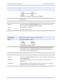
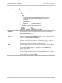
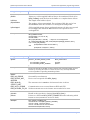
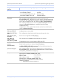
Crossover cable
All sample programs use the transmitting adapter’s BRG clock source
as the master for both transmitter and receiver. The crossover cable
for these tests should cross the TxD to RxD lines and the TxClk(DTE)
to RxClk(DCE) lines. For RS-422/485, like polarities should match.
Figure 10 - RS-232 Crossover cable pinouts
Figure 11 - RS-422/485 Crossover cable pinouts
Rev 01 (2/6/2003)
Page 30
Quatech Syncdrive Plus User’s Manual
Troubleshooting
Troubleshooting
Verify that the hardware is configured properly
Note: The compiled Syncdrive
Plus example programs are
good tools to use for this
purpose because we test them
all in a known-good system
before shipping.
Hint: Run the program with a
/? parameter on the command
line for a short help screen.
.
A good first step in solving problems is to make sure that there are no
hardware conflicts. One way to do this is to try a known-good
Syncdrive Plus application on the hardware.
The LPBCKBI2K.EXE program is the best place to start because it
does not require you to connect any cables. It can accept as command
line input whatever resource settings are being used on the installed
MPA-series adapter.
LPBCKBI2K runs continuous frames in loopback mode. As it runs, it
prints each frame to the screen. If LPBCKBI2K is able to run
successfully, then you know that the hardware configuration is good.
If LPBCKBI2K crashes or locks up, it indicates that the hardware is
not configured properly. You may need to change some of the
hardware settings to avoid conflicts with other devices in the system.
Check the Syncdrive Plus configuration
If the hardware is verified to be good, then the problem must be
somewhere in the software. The first place to check is the
MPA_CONFIG configuration structure. Double check that all
variables in this structure are set properly.
Check the clock sourcing
If transmit or receive operations just don't seem to work right, double
check the RxClockSource and TxClockSource variables in the
MPA_CONFIG configuration structure. In conjunction with the
hardware manual for the MPAX-series adapter, make sure that any
clock signals on the cable are routed to the proper SCC inputs and
outputs, and that the modes in the RxClockSource and TxClockSource
variables are set properly.
Know the speed limits
There are limits on how fast the MPAX-series adapters can operate
under Syncdrive Plus. Most of the limitations are the result of
external cabling, the upper limits of the SCC, and clock jitter as that
upper limit is approached. Syncdrive Plus limits the maximum rate to
1/6 of the input clock frequency.
If you need a baud rate that cannot be achieved with the standard
clock frequency, contact Quatech Technical Support. It may be
possible to use a custom clock oscillator to change the available baud
rate selections.
Rev 01 (2/6/2003)
Page 31
Quatech Syncdrive Plus User’s Manual
Error codes
Error codes
Note: The error code meaning
may vary, depending on the
Syncdrive Plus command.
.
The definitive source for error codes is the QuaDef.h include file. The
error codes for Release 1.00 are duplicated here for convenience. The
significance of the error code depends on the function returning it.
See the return code explanation for the API of interest in the document.
Error message
Description
ERR_NO_ERROR
Successful operation; operation varies, depending on
command
ERR_BAD_RETURN_SIZE
The (address/frame count/frame size/configuration/
driver version) length returned did not match expected
ERR_COULDN’T_CLOSE_DEVICE
Unsuccessful close
ERR_COULDN’T_OPEN_DEVICE
Unsuccessful open
ERR_DATA_CRC
A CRC error occurred during transfer
ERR_DATA_OVERRUN
A data overrun occurred because the caller buffer was
too small for the frame received
ERR_DEVICE_NOT_OPENED
Device was not opened with MPA-Open()
ERR_ERROR_READING_DATA
Error receiving frame occurred
ERR_ERROR_WRITING_DATA
Error transmitting frame occurred
ERR_INCORRECT_NUM_BYTES_READ
For non-overlapped I/O only; bytes received differ from
requested; not necessarily an error if a larger buffer was
allocated than required
ERR_INCORRECT_NUM_BYTES_WRITTEN
Number of bytes written differs from number expected
ERR_INVALID_FOR_NON_OVERLAPPED
This call is not valid for non-overlapped I/O
ERR_INVALID_PARAMETERS_PASSED
Device opened as overlapped but storage for an
overlapped structure not passed in lpOverlapped;
WAIT cannot be TRUE when overlapped is NULL;
ERR_INVALID_STRUCT_SIZE
The structure size in structLen did not match size in driver
ERR_IOCTL_ERROR
Communication error occurred between DLL and SYS
ERR_IO_STILL_PROGRESSING
I/O is still occurring in the background; Bytestransferred is placed in pBytesTransferred
ERR_NOTHING_TO_DO
Neither transmit nor receive frames were marked to be
reset
ERR_READ_PENDING
Receiving frame in the background since device opened
as overlapped
ERR_TRANSFER_STATUS
Driver failed to return the correct status to the DLL;
probable hardware failure
ERR_WRITE_PENDING
Returned when driver is set up for overlapped I/O;
indicates that driver is still working on the last write
Rev 01 (2/6/2003)
Page 32
Quatech Syncdrive Plus User’s Manual
Appendix A – Definitions
Appendix A
Definitions
Term
Definition
API (Application Programming
Interface)
An application program interface is the specific method prescribed by
a computer operating system or by an application program by which a
programmer writing an application program can make requests of the
operating system or another application.
Asynchronous communication
In general, asynchronous is an adjective describing objects or events
that are not coordinated in time. Asynchronous communications do
not employ a clocking signal. Instead, they rely on start and stop bits,
which is a simple but inefficient scheme.
Contrast with synchronous communication.
Bit-sync
Sub-division of synchronous communication. Bit-synchronous
transfers treat a data block as a series of data bits with no specific
character boundaries. Used to implement SDLC or HDLC.
BRG (Baud Rate Generator)
An SCC feature that is used for internally generating a data clocking
signal.
Byte-sync
Sub-division of synchronous communication. Byte-synchronous
transfers treat a data block as a series of fixed-length characters.
Used to implement BISYNC. Not currently supported by Syncdrive
Plus.
CRC
Cyclic redundancy checking is a method of checking for errors in data
that has been transmitted on a communications link. A sending
device applies a 16- or 32-bit polynomial to a block of data that is to
be transmitted and appends the resulting cyclic redundancy code
(CRC) to the block. The receiving end applies the same polynomial to
the data and compares its result with the result appended by the
sender. If they agree, the data has been received successfully. If not,
the sender can be notified to resend the block of data.
DPLL (Digital Phase Locked
Loop)
Used to encode or decode a clocking signal within a data stream.
A Digital PLL (DPLL) circuit may consist of a serial shift register
which receives digital input samples (extracted from the received
signal), a stable local clock signal which supplies clock pulses to the
shift register to drive it and a phase corrector circuit which takes the
local clock and regenerates a stable clock in phase with the received
signal by slowly adjusting the phase of the phase of the regenerated
clock to match the received signal.
The DLL is typically used in situations where separate signals for
transmit and receive data clocks are not available in the cables. The
clocking information is embedded in the data itself.
Rev 01 (2/6/2003)
Page 33
Quatech Syncdrive Plus User’s Manual
Appendix A – Definitions
Term
Definition
Frame
In telecommunications, a frame is data that is transmitted between
network points as a unit complete with addressing and necessary
protocol control information. A frame is usually transmitted serial bit
by bit and contains a header field and a trailer field that "frame" the
data. (Some control frames contain no data.)
PCI bus
PCI (Peripheral Component Interconnect) is an interconnection
system between a microprocessor and attached devices in which
expansion slots are spaced closely for high-speed operation. PCI is
designed to be synchronized with the clock speed of the
microprocessor.
Protocol
In information technology, a protocol is the special set of rules that
end points in a telecommunication connection use when they
communicate.
SCC (Serial Communications
Controller)
The integrated circuit that handles the bulk of the hardware functions
for the serial channel. Typically, the SCC will either be an AM85C3010 or Z85230-10 on Quatech MPA-series adapters.
Synchronous communication
In general, synchronous is an adjective describing objects or events
that are coordinated in time. Synchronous communications use
clocking information sent with the data. This eliminates the need for
start and stop bits and also allows for a more continuous data stream
than is possible with asynchronous communication. Reduced
overhead and higher possible speeds are the main advantages of
synchronous communications.
Contrast with asynchronous communication.
Rev 01 (2/6/2003)
Page 34