1
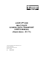
LOOP-H
3300
MULTI RATE
G.SHDSL DATA TRANSPORT
USER'S MANUAL
(Stand Alone - E1/ T1)
LOOP TELECOMMUNICATION INTERNATIONAL, INC.
8F, NO. 8, HSIN ANN RD.
SCIENCE-BASED INDUSTRIAL PARK
HSINCHU, TAIWAN
Tel:
+886-3-578-7696
Fax:
+886-3-578-7695
2005 Loop Telecommunication International, Inc. All rights reserved.
Loop-H is a trade mark of Loop Telecommunication International, Inc.
P/N: 51.LH3300.1SE
05/2005 Version 1.8
Loop-H 3300 Multi Rate G.SHDSL Data Transport User’s Manual (Stand Alone E1)
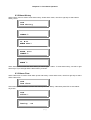
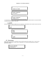
TABLE OF CONTENTS
1
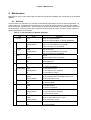
PRODUCT DESCRIPTION.....................................................................1-1
1.1
1.2
1.3
2
INSTALLATION......................................................................................2-1
2.1
2.2
2.3
2.4
2.4.1
2.4.2
3
Overview .......................................................................................................... 1-1
Applications..................................................................................................... 1-2
Product Specifications ................................................................................... 1-4
Mechanical Installation................................................................................... 2-1
Electrical Installation ...................................................................................... 2-2
Line Power and Sealing Current Options..................................................... 2-3
Configuration Setting ..................................................................................... 2-5
Hardware Configuration Setting .......................................................... 2-5
Software Configuration Setting ........................................................... 2-5
OPERATION ..........................................................................................3-1
3.1
Mode................................................................................................................. 3-1
3.2
Clocks .............................................................................................................. 3-1
3.3
Terminal configuration ................................................................................... 3-1
3.4
Load Default .................................................................................................... 3-1
Alarms ................................................................................................................................ 3-1
3.6
Reports............................................................................................................. 3-3
3.7
Date and Time.................................................................................................. 3-3
3.8
Front Panel Lock ............................................................................................. 3-3
3.9
LED Indicators................................................................................................. 3-4
4
MAINTENANCE .....................................................................................4-1
4.1
4.2
4.3
4.3.1
4.3.2
5
Self test ............................................................................................................ 4-1
Diagnostics...................................................................................................... 4-2
Loopbacks ....................................................................................................... 4-2
Loopbacks Toward Network ................................................................ 4-2
Loopbacks Toward Customer.................................................................... 4-2
E1 FRONT PANEL OPERATION...........................................................5-1
5.1
Main Menu ....................................................................................................... 5-2
5.2
Configuration Menu ........................................................................................ 5-2
5.2.1
xDSL Mode ................................................................................................... 5-3
5.2.2
Clock Source................................................................................................ 5-3
5.2.3
E1 Menu........................................................................................................ 5-4
5.2.3.1
Slave E1 ..................................................................................... 5-6
5.2.3.2
Line Rate .................................................................................... 5-7
5.2.3.3
Loop Number............................................................................. 5-7
5.2.3.4
Baud Rate .................................................................................. 5-9
5.2.3.5
Adaptive Line Rate.................................................................... 5-9
5.3
Alarm .............................................................................................................. 5-11
5.3.1
Alarm Queue ........................................................................................ 5-11
5.3.2
Alarm History....................................................................................... 5-11
5.3.3
Alarm Clear .......................................................................................... 5-12
5.3.4
Alarm Setup ......................................................................................... 5-12
5.3.4.1
Alarm Type .............................................................................. 5-12
5.3.4.2
Alarm Threshold ..................................................................... 5-13
5.3.5
Alarm Cut Off ....................................................................................... 5-13
5.4
Diagnostics Menu ......................................................................................... 5-14
5.4.1
xDSL Loopback Menu......................................................................... 5-14
5.4.2
E1 Loopback Menu ............................................................................. 5-14
5.4.3
Slave Loopback Menu ........................................................................ 5-15
5.4.4
BERT..................................................................................................... 5-16
5.5
Performance .................................................................................................. 5-16
5.5.1
Reset Performance.............................................................................. 5-16
5.5.2
Master Loop1, Loop2 and E1 ES/SES/UAS Performance .............. 5-17
5.5.3
Slave Loop1, Loop2 and E1 ES/SES/UAS Performance................. 5-19
i
Loop-H 3300 Multi Rate G.SHDSL Data Transport User’s Manual (Stand Alone E1)
5.6
5.7
5.8
5.8.1
5.8.2
6
Status ............................................................................................................. 5-21
Information .................................................................................................... 5-23
Miscellaneous................................................................................................ 5-24
Lock Front Panel ................................................................................. 5-24
Password Setup .................................................................................. 5-25
T1 FRONT PANEL OPERATION ...........................................................6-1
6.1
Main Menu ....................................................................................................... 6-1
6.2
Configuration Menu ........................................................................................ 6-2
6.2.1
xDSL Mode ................................................................................................... 6-2
6.2.2
Clock Source................................................................................................ 6-2
6.2.3
T1 Menu ........................................................................................................ 6-3
6.2.3.1
Slave T1 ..................................................................................... 6-5
6.2.3.2
Line Rate .................................................................................... 6-6
6.2.3.3
Loop Number............................................................................. 6-7
6.2.3.4
Baud Rate .................................................................................. 6-8
6.2.3.5
Adaptive Line Rate.................................................................... 6-8
6.3
Alarm .............................................................................................................. 6-10
6.3.1
Alarm Queue ........................................................................................ 6-10
6.3.2
Alarm History....................................................................................... 6-11
6.3.3
Alarm Clear .......................................................................................... 6-11
6.3.4
Alarm Setup ......................................................................................... 6-12
6.3.4.1
Alarm Type .............................................................................. 6-12
6.3.4.2
Alarm Threshold ..................................................................... 6-12
6.3.5
Alarm Cut Off ....................................................................................... 6-13
6.4
Diagnostics Menu ......................................................................................... 6-13
6.4.1
xDSL Loopback Menu......................................................................... 6-13
6.4.2
T1 Loopback Menu.............................................................................. 6-14
6.4.3
Slave Loopback Menu ........................................................................ 6-14
6.4.4
BERT..................................................................................................... 6-15
6.5
Performance .................................................................................................. 6-15
6.5.1
Reset Performance.............................................................................. 6-16
6.5.2
Master Loop1, Loop2 and T1 ES/SES/UAS Performance............... 6-16
6.5.3
Slave Loop1, Loop2 and T1 ES/SES/UAS Performance................. 6-18
6.6
Status ............................................................................................................. 6-20
6.7
Information .................................................................................................... 6-22
6.8
Miscellaneous................................................................................................ 6-22
6.8.1
Lock Front Panel ................................................................................. 6-23
6.8.2
Password Setup .................................................................................. 6-24
7
TERMINAL OPERATIONS.....................................................................7-1
7.1
7.1.1
7.1.2
7.2
7.2.1
7.2.2
7.3
7.3.1
7.3.2
7.4
7.4.1
7.4.2
7.5
7.5.1
7.5.2
7.6
7.6.1
7.6.2
7.7
7.8
Main Menu ....................................................................................................... 7-1
For E1 Interface ..................................................................................... 7-1
For T1 Interface ..................................................................................... 7-1
System Configuration..................................................................................... 7-2
For E1 Interface ..................................................................................... 7-2
For T1 Interface ..................................................................................... 7-2
System Status ................................................................................................. 7-3
For E1 Interface ..................................................................................... 7-3
For T1 Interface ..................................................................................... 7-3
Performance Report ....................................................................................... 7-4
For E1 Interface ..................................................................................... 7-4
For T1 Interface ..................................................................................... 7-4
Alarm Queue.................................................................................................... 7-5
For E1 Interface ..................................................................................... 7-5
For T1 Interface ..................................................................................... 7-5
Alarm History................................................................................................... 7-6
For E1 Interface ..................................................................................... 7-6
For T1 Interface ..................................................................................... 7-6
Customer Information .................................................................................... 7-7
HDSL Information ........................................................................................... 7-7
ii
Loop-H 3300 Multi Rate G.SHDSL Data Transport User’s Manual (Stand Alone E1)
7.9
7.9.1
7.9.2
7.10
7.10.1
7.10.2
7.11
7.11.1
7.11.2
7.12
7.13
7.14
7.15
7.16
7.16.1
7.16.2
7.17
7.18
7.19
7.20
System Setup .................................................................................................. 7-8
General Setup ........................................................................................ 7-8
Advance Setup .................................................................................... 7-10
Loopback and Test ....................................................................................... 7-11
For E1 Interface .................................................................................. 7-11
For T1 Interface .................................................................................. 7-11
Alarm Setup ................................................................................................... 7-12
For E1 Interface .................................................................................. 7-12
For T1 Interface .................................................................................. 7-12
Clear Alarm Queue........................................................................................ 7-13
Clear performance Data ............................................................................... 7-13
Customer Information Setup ....................................................................... 7-13
Password Setup ............................................................................................ 7-13
Line Rate ........................................................................................................ 7-14
For E1 Interface .................................................................................. 7-14
For T1 Interface .................................................................................. 7-15
Load Default Configuration and Reset ....................................................... 7-16
System Reset................................................................................................. 7-16
Alarm Cut Off................................................................................................. 7-17
Upgrade Firmware ........................................................................................ 7-18
LIST OF FIGURES
FIGURE 1- 1 APPLICATION OF LOOP-H 3300 G.SHDSL DATA TRANSPORT SERIES .................. 1-2
FIGURE 2- 1 LOOP-H 3300 STAND ALONE FRONT PANEL VIEW ............................................... 2-1
FIGURE 2- 2 LOOP-H 3300 REAR PANELS – AC POWER .......................................................... 2-2
FIGURE 2- 3 LOOP-H 3300 REAR PANELS – DC POWER .......................................................... 2-2
FIGURE 2- 4 MAIN BOARD WITHOUT LINE POWER OR SEALING CURRENT .................................. 2-3
FIGURE 2- 5 LINE POWER SINKING CARD ................................................................................ 2-4
FIGURE 2- 6 2-PAIR AND 1-PAIR SEALING CURRENT SINKING CARD ......................................... 2-4
FIGURE 2- 7 JUMPER POSITION FOR E1 CARD OF 8370 CHIP BNC INTERFACE ( 75 Ω ).............. 2-6
FIGURE 2- 8 JUMPER POSITION FOR E1 CARD OF 8370 CHIP TP INTERFACE ( 120 Ω )............... 2-6
FIGURE 3- 1 STATUS AND PERFORMANCE REFERENCE POINTS ................................................ 3-1
FIGURE 3- 2 LED FRONT PANEL ............................................................................................. 3-4
FIGURE 4- 1 LOOPBACKS AVAILABLE ....................................................................................... 4-2
FIGURE 5- 1 LCD MENU TREE – E1 ....................................................................................... 5-2
LIST OF TABLES
TABLE 2- 1 CONSOLE CABLE ................................................................................................... 2-3
TABLE 2- 2 V.35/M34 DTE PORT PIN DEFINITION .................................................................. 2-7
TABLE 2- 3 V.35/DB25 DTE PORT PIN DEFINITION ................................................................ 2-8
TABLE 2- 4 E1/RJ48 LINE CONNECTOR ................................................................................... 2-9
TABLE 2- 5 LINE XDSL CONNECTOR ..................................................................................... 2-9
TABLE 3- 1 PERFORMANCE PARAMETER ................................................................................. 3-3
TABLE 4- 1 LED INDICATION FOR NORMAL OPERATION............................................................ 4-1
iii
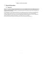
Chapter 1 Product Description
1 Product Description
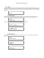
1.1 Overview
The Loop-H 3300 is a family of products that are based on the G.SHDSL transmission standard proposed by
Bellcore. They use the standard 16PAM line format over twisted copper pairs to provide digital transport for
a variety of data formats and data rates. The distances that this technology can span without repeaters are
dependent on the data rate.
In one application, Loop-H 3300 can provide E1 or T1 transport without the need for is loop repeaters and
copper conditioning requirements, so long as the cables meet CSA (carrier service area) guidelines.
In another application, Loop-H 3300 can provide high speed V.35 data transport over twisted copper pairs,
either terminating in another V.35 interface, or as access to E1 or T1 networks.
This manual covers the stand alone models of the Loop-H 3300 with E1 interface only.
1-1
Chapter 1 Product Description
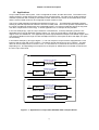
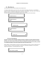
1.2 Applications
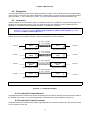
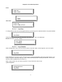
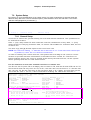
Loop-H 3300 must be used in pairs. One is configured as master, and the other slave. The master unit is
usually located in central offices and is usually a rack-mounted model. The slave unit is usually located at
customer's premises and is usually a stand-alone model. Both the LCD version of the stand-alone model
and the rack-mounted model can be configured as either master or slave.
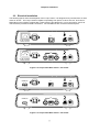
The Loop-H 3300 application examples are illustrated in Figure 1-1. This application essentially replaces
existing or planned requirements where E1 lines are normally used. The E1 line repeater requirements and
the copper conditioning requirements are considerably eased. The result is significant savings in loop plant
cost when compared to E1 technology. A similar application for T1 transport is also possible.
In the next example (b), a pair of Loop-H 3300 has V.35 interfaces. In the top example (a) which is not
applicable to this Loop-H 3300 DTE model of Figure 1-2. They are connected by a single pair of twisted
copper wires, the 16PAM line. This application provides high-speed data transport over twisted copper wires.
The spanning distances are longer for rates 768 Kbps and below. If the speed is above 768 Kbps, two pairs
are necessary.
In the bottom example (c) and (d) of Figure 1-1, one unit of a pair of Loop-H 3300 is equipped with a V.35
interface and the other with an E1 interface. This allows remote data access to an E1 network. The data
rates can be n*64 Kbps where n can be 1 to 32. If n are less than 31, fractional E1 services is provided.
Depending on n, and depending on line speed one or two pairs of 16PAM lines are needed to interconnect
the two Loop-H 3300 units.
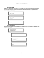
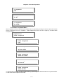
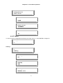
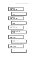
Two-Loop
E1/T1
Loop-H 3300
Master
E1/DTE: 1032 - 200 Kbps
T1: 776 - 200 Kbps
Loop-H 3300
Slave
E1/T1
Loop-H 3300
Slave
DTE/
Router
E1/DTE: 2056 - 200 Kbps
T1: 1544 - 200 Kbps
Loop-H 3300
Slave
E1/T1
E1/T1 to E1/T1
E1/DTE: 1032 - 200 Kbps
T1: 776 - 200 Kbps
E1/T1
Loop-H 3300
Master
E1/T1 to DTE/Router
One-Loop
E1/T1
Loop-H 3300
Master
E1/T1 to E1/T1
E1/T1
Loop-H 3300
Master
E1/DTE: 2056 - 200 Kbps
T1: 1544 - 200 Kbps
Loop-H 3300
Slave
DTE/
Router
E1/T1 to DTE/Router
Figure 1- 1 Application of Loop-H 3300 G.SHDSL Data Transport Series
1-2
Chapter 1 Product Description
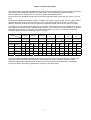
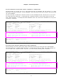
The distances achievable with 16PAM technology are dependent of the wire size and operating environment.
The following table should be used only as a rough guide. The actual distance depends on many
environmental factors. Maximum is for no noise. Typical is with 0dB ETSI noise.
By laws of physics, G.SHDSL should reach about 20% longer than HDSL. Some say 40%, that is if you are
lucky.
Because of the different modulation method, G.SHDSL has a lower frequency band. Loss of copper cable is
proportional to the square root of the frequency. Thus if you half the frequency, you get 1.414 times the
distance. G.SHDSL is about 40% lower in frequency compared to HDSL, thus has only 20% more reach.
The distance you can reach is determined not by loss alone. Cross-talk also plays an important part. Thus if
you avoid the frequencies where cross-talk noise is present, you can also reach longer distances. Cross-talk
is proportional to frequency. Therefore, if you reduce the frequency by 40%, by cross-talk consideration
alone you get 40% more reach. Nothing is quite so simple.
Line Speed
Data Rate
Guage- Wire Dia.
ohms/Km
Distances
Distances
Distances
Distances for
T1
Distances for
E1
Distances for
T1
Distances for
E1
264 Kbps
392 Kbps
520 Kbps
776 Kbps
1032 Kbps
1544 Kbps
2056 Kbps
(4x64Kbps+8Kbps) (6x64Kbps+8Kbps) (8x64Kbps+8Kbps) (12x64Kbps+8Kbps) (16x64Kbps+8Kbps) (24x64Kbps+8Kbps) (32x64Kbps+8Kbps)
4 x 64 Kbps
6 x 64 Kbps
8 x 64 Kbps
24 x 64 Kbps
32 x 64 Kbps
24 x 64 Kbps
32 x 64 Kbps
Max.
Min.
Max.
Min.
Max.
Min.
Max.
Min.
Max.
Min.
Max.
Min.
Max.
Min.
19-56Ω
0.9 mm
27.86
16.8
22.82
13.8
19.6
11.88
14
8.4
11.62
6.96
10.08
6.12
8.4
5.04
22-111Ω
0.6 mm
17.78
10.8
15.12
9.12
13.3
8.04
9.66
5.88
8.26
5.04
7.28
4.44
6.16
3.72
24-176Ω
0.5 mm
12.46
7.56
10.78
6.6
9.66
5.88
7.14
4.32
6.16
3.72
5.6
3.36
4.76
2.88
26-280Ω
0.4 mm
8.96
5.4
7.98
4.8
7.14
4.32
5.46
3.24
4.76
2.88
4.34
2.64
3.78
2.28
Through the EOC (Embedded Operations Channel), the master can provide administrative, reporting, and
diagnostic functions to the remote unit as well. Administrative functions include configuration, status
indication of both ends. Reports include 15-minute and 24-hour performance and alarms. Diagnostics
include loop backs, error testing, performance monitoring, and alarm history.
1-3
Chapter 1 Product Description
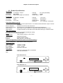
1.3 Product Specifications
T1 Interface
Line Rate
Line Code
Input Signal
E1 Interface
Line Rate
Line Code
Input Signal
1.544 Mbps ± 50 bps
AMI / B8ZS
ABAM cable length up to 655 feet
Framing
Connector
Output Signal
2.048 Mbps ± 50 PPM
HDB3
ITU G.703
Framing
Connector
Output Signal
Electrical
D4 / ESF (selectable)
RJ48C
DSX1
ITU G.704
BNC/RJ48C
ITU G.703
75Ω Coax/120Ω twisted pair
Performance Monitor (E1/T1)
Performance Store
The last 24 hours performance in 15-minute intervals and last 7 days in 24-hour
summary
Monitor Registers
Network, E1/T1/DTE, and remote site
Performance Reports Errored Second, Unavailable Second, Severe Errored Second
Alarm History
Alarm Type, Loop1, Loop2, E1/T1 (LOS, ES, SES), and DTE Clock Loss
Alarm Queue
Contains 40 alarm records which record the latest alarm type, and date & time
xDSL Line Interface
Full duplex with adaptive echo cancellation 16PAM line coding
Unconditioned 19-26 AWG twisted pair
Clock
xDSL looped, Internal, or E1/T1/DTE
Console Port
Connector
DB9S at front panel
Electrical
RS232 interface (DCE)
Protocol
Menu driven VT-100 terminal
System Configuration Parameters (All in non-volatile memory)
Active Configuration
Current working configuration
Default Configuration Manufacture default configuration
Diagnostics Test
xDSL Loopback
To-DTE, To-LINE
DTE Loopback
To-DTE, To-LINE
E1 Loopback
To-E1, To-LINE
Slave Loopback
DTE-Side, Line-Side
Front Panel
Keypad 4 keys:
left arrow, right arrow, ESC, and ENTER
LCD
2-line by 16-character
LED
Front Panel for E1:
TM
Loop-H
ESC
G.shdsl
G.shdsl
SYNC/TEST
RAI/AIS
BPV
E1
ENTER
POWER
LOOP1
LOOP2
TEST
ALARM
DTE
RTS
TD
TEST
RD
CLK-LOSS
Front Panel for T1:
TM
Loop-H
ESC
G.shdsl
G.shdsl
SYNC/TEST
YEL/AIS
BPV
T1
ENTER
POWER
LOOP1
LOOP2
TEST
1-4
ALARM
DTE
RTS
TD
TEST
RD
CLK-LOSS
Chapter 1 Product Description
Physical/Electrical
Dimensions
Power
Temperature range
Humidity
Mounting
Compliance
EMI/EMC
Safety
G.SHDSL
29 x 6 x 22 cm (WxHxD)
7.5 Watts max without line power or 24 Watts max with line power
0 – 50 °C
0 – 95% RH (non-condensing)
Desk-top stackable
Rack Mount tray available
EN55022, EN50081-1, EN50082-1
EN60950
G.991-2, G.994-1
1-5
Chapter 2 Installation
2 Installation
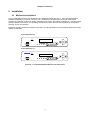
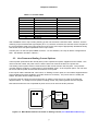
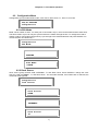
2.1 Mechanical Installation
Loop-H 3300 Stand-Alone unit is designed to be installed as a desk top unit, or, using optional hardware,
installed individually in a 19-inch or 23-inch rack. Selection for the placement of Loop-H 3300 should
consider the locations of entrance cables, availability of ac power, and cables to equipment. The site should
provide a stable environment. The operating area should be clean and free from extremes of temperature,
humidity, shock, and vibration.
Relatively humidity should stay between 0 and 90%. Do not operate the unit at an altitude greater than 3500
meters (10,000 feet).
Front Panel for E1:
TM
Loop-H
ESC
G.shdsl
G.shdsl
SYNC/TEST
RAI/AIS
BPV
E1
ENTER
POWER
LOOP1
LOOP2
TEST
ALARM
DTE
RTS
TD
TEST
RD
CLK-LOSS
Front Panel for T1:
TM
Loop-H
ESC
G.shdsl
G.shdsl
SYNC/TEST
YEL/AIS
BPV
T1
ENTER
POWER
LOOP1
LOOP2
TEST
ALARM
DTE
RTS
TD
TEST
RD
CLK-LOSS
Figure 2- 1 Loop-H 3300 Stand Alone Front Panel View
2-1
Chapter 2 Installation
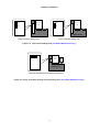
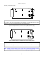
2.2 Electrical Installation
The following figures show the backplane of the Loop-H 3300. It is designed to be powered from AC wall
mains or 48 Vdc. The Loop-H 3300 is capable of operating from power of 100 to 240 vac, 50 to 60 Hz.
Depending on the interface configuration, RJ45 jacks are provided for E1 or line connections, and V.35
connectors are provided for data connections. The 16PAM lines are connected via RJ45 jacks.
T1
ALM
LINE
NC NO COM
AC LINE, 100-240VAC,
50/60Hz, 0.3A MAX.
E1
RX-IN
TX-OUT
ALM
LINE
NC NO COM
AC LINE, 100-240VAC,
50/60Hz, 0.3A MAX.
Figure 2- 2 Loop-H 3300 Rear Panels – AC Power
POWER (DC)
T1
ALM
LINE
NC NO COM
-V +V
E1
POWER (DC)
RX-IN
TX-OUT
ALM
NC NO COM
-V +V
Figure 2- 3 Loop-H 3300 Rear Panels – DC Power
2-2
LINE
Chapter 2 Installation
Table 2- 1 Console Cable
Pin Number
1
2
3
4
5
6
7
8
9
Signal
Data Carrier Detect
Receive Data
Transmit Data
Unassign
Singal Ground
Data Set Ready
Unassign
Clear to send
Unassign
Source
To DTE
To DTE
From DTE
To DTE
To DTE
After installation of the Loop-H 3300, powering up the unit will cause a self test to start. However, until the
matching Loop-H 3300 and the signal inputs (E1 or T1) are also connected, the self test will not complete to
the synchronization state of the input signal and of the Loop1 (and Loop2 if appropriate) 16PAM line facility.
See Section 8 for front panel operations of the Loop-H 3300.
Console port is on the front panel DB9S connector. For this interface, the Loop-H 3300 is configured as a
DCE. Pin definition is listed in Table 2-1.
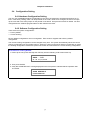
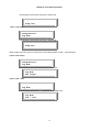
2.3 Line Power and Sealing Current Options
The line power option allows the remote (slave) unit to operate from power supplied from the master. One
unit must be the master, the power source, and the other unit must be the slave, the power sink.
The sealing current option causes a small amount of DC current to flow in the wire pairs. This prevents
corrosion built-up at splices, a useful option in humid weather areas. As in the power option, one unit must
be source with DC power and the other sink with AC or DC power.
If the Loop-H 3300 is ordered with "Line Power" or "Sealing Current" option, the unit will be shipped with the
proper boards and jumpers installed. No further actions is necessary. The power source is usually the
master, the power sink is usually the slave.
If the user wants to change a unit from line power or sealing current source to a sink, then follow the
diagrams below. To change from line power to sealing current, the powering board must be changed.
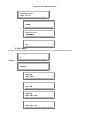
Note also that when the unit is operated as power source, that unit must be DC powered.
JP12
JP13
DTE/ E1/ T1
Card
AC/ DC
Power
Main Board
Figure 2- 4 Main Board without Line Power or Sealing Current ( For H3300 Stand Alone only )
2-3
JP5
1 2 3 1 2 3
1 2 3 1 2 3
Chapter 2 Installation
DTE/ E1/ T1
Card
JP6
DTE/ E1/ T1
Card
JP5
JP6
Main Board
Main Board
2-Pair Line Power Sinking Card
1-Pair Line Power Sinking Card
Figure 2- 5 Line Power Sinking Card ( For H3300 Stand Alone only )
JP12
JP13
DTE/ E1/ T1
Card
AC/ DC
Power
Main Board
2-Pair and 1-Pair Sealing Current Sinking Card for Slave
Figure 2- 6 2-Pair and 1-Pair Sealing Current Sinking Card ( For H3300 Stand Alone only )
2-4
Chapter 2 Installation
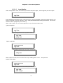
2.4 Configuration Setting
2.4.1 Hardware Configuration Setting
The only user modifiable hardware configuration is the choice of balanced or unbalanced interface for E1
lines. If the factory setting, which can be specified on the order, needs to be changed, the user must open
up the case and move some jumper on the printed circuit board. See previous section for details. All other
configurations are software programmable. No DIP switches are used.
2.4.2 Software Configuration Setting
There are three system configurations:
• Factory default
• Current working
Factory default configurations are not changeable. Each series is shipped with a factory default
configuration.
The current working configuration can be changed at any time. The system automatically stores the current
working configuration into nonvolatile memory. When the system is turned off and then turned back on again,
the working configuration used before power was turned off is retrieved as the current working configuration.
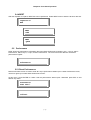
Procedure for Loading Default:
1. Power-up the unit, press and keep the ESC key until the following LCD screen shows up.
TEST...002
V1.06 01/07/2003
2. Then press ENTER.
3. Verify that LOAD DEFAULT is being displayed on the front panel to indicate that the operation was
successful.
LOAD DEFAULT
CONFIGURATION
2-5
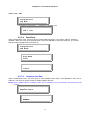
Chapter 2 Installation
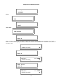
JP17
JP14 JP15
JP16
BNC2
JP11
JP9
JP13 JP12
JP18
BNC1
JP10
Below are jumper position for BNC:
NOTE:
For 75 ohm E1 card, jumper 16 can be OPEN or ON. If the jumper 16 is OPEN, BNC connector is set to
Unassigned. If the jumper 16 is ON, BNC connector is set to Chassis Ground.
JP17
JP10
JP13 JP12
JP14 JP15
JP16
BNC2
JP11
JP9
BNC1
JP18
Figure 2- 7 Jumper Position for E1 card of 8370 chip BNC interface ( 75 Ω )
Figure 2- 8 Jumper Position for E1 card of 8370 chip TP interface ( 120 Ω )
NOTE:
For 120 ohm E1 card, jumper 17 can be OPEN or ON. If the jumper 17 is OPEN, pin 7 and pin 8 of RJ
connector is set to Unassigned. If the jumper 17 is ON, pin 7 and pin 8 of RJ connector is set to Chassis
Ground.
NOTE: When BNC connector is selected, the user has the option of grounding the received BNC shield by
installing a jumper clip on the jumper location. This is usually not necessary, but if you have any
noise on your device it can often be filtered out by using this grounding process.
2-6
Chapter 2 Installation
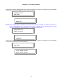
Connections to the E1 or T1 lines are supported by RJ48 or BNC connector. Connections to the V.35 are
supported by either M34 or DB25 connector. Connections to the 16PAM lines are by the RJ48 connector.
The pin definitions for V.35/M34 DTE port, V.35/DB25 DTE port, EIA530/DB25 DTE port, X.21/DB15 DTE
port, RS449/DB37 DTE port, E1/RJ48 line connector, and line xDSL connector are listed in Tables 2-2 to 2-8.
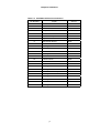
Table 2- 2 V.35/M34 DTE Port Pin Definition
Pin Number
Signal
Source
A
B
Cable Shield
Signal Ground
C
Request To Send
DTE
D
Clear To Send
DCE
E
Data Set Ready
DCE
F
Data Carrier Detect
DCE
H
Data Terminal Ready
DTE
J
Unassigned
K
Unassigned
L
Unassigned
M
Unassigned
N
Unassigned
P
Transmit Data
DTE
R
Receive Data
DCE
S
Transmit Data Return
DTE
T
Receive Data Return
DCE
U
External Clock
DTE
V
Receive Clock
DCE
W
External Clock Return
DTE
X
Receive Clock Return
DCE
Y
Transmit Clock
DCE
Z
Unassigned
AA
Transmit Clock Return
BB
Unassigned
CC
Unassigned
DD
Unassigned
EE
Unassigned
FF
Unassigned
HH
Unassigned
JJ
Unassigned
KK
Unassigned
LL
Unassigned
MM
Unassigned
NN
Unassigned
2-7
DCE
Chapter 2 Installation
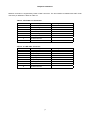
Table 2- 3 V.35/DB25 DTE Port Pin Definition
Pin Number
Signal
Source
1
2
Cable Shield
Transmit Data
DTE
3
Receive Data
DCE
4
Request To Send
DTE
5
Clear To Send
DCE
6
Data Set Ready
DCE
7
Signal Ground
8
Data Carrier Detect
DCE
9
Receive Clock Return
DCE
10
Unassigned
11
External Clock Return
DTE
12
Transmit Clock Return
DCE
13
Unassigned
14
Transmit Data Return
DTE
15
Transmit Clock
DCE
16
Receive Data Return
DCE
17
Receive Clock
DCE
18
Unassigned
19
Unassigned
20
Data Terminal Ready
21
Unassigned
22
Unassigned
23
Unassigned
24
External Clock
25
Unassigned
2-8
DTE
DTE
Chapter 2 Installation
Network connection is supported by RJ48 or BNC connector. The line interface is labeled with LINE. RJ48
connector pin definition is listed in Table 2-7.
Table 2- 4 E1/RJ48 Line Connector
Pin Number
Signal
Signal Direction
1
2
3
Receive Tip
Receive Ring
Unassigned
From E1 Network
From E1 Network
4
5
6
Transmit Tip
Transmit Ring
Unassigned
To E1 Network
To E1 Network
7
Chassis Ground
8
Chassis Ground
Table 2- 5 LINE xDSL Connector
Pin Number
Signal
Signal Direction
1
2
3
Loop2 Tip
Loop2 Ring
Unassigned
To/ From xDSL Network
To/ From xDSL Network
4
5
6
Loop1 Tip
Loop1 Ring
Unassigned
To/ From xDSL Network
To/ From xDSL Network
7
Chassis Ground
8
Chassis Ground
2-9
Chapter 3 Operation
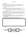
3 Operation
Many of the factories set default options can be changed either by Front Panel Operation or by Terminal
Operation. See appropriate sections for detail. The allowed operations are described below.
All configuration settings are stored in non-volatile memory. Thus for all components of the Loop-H 3300
system, upon power-up, the last settings will be in place.
3.1 Mode
Operated in pairs, one Loop-H unit must have its mode set as master and the other slave. The remote unit,
slave or master updates its configuration accordingly upon receipt of the new configuration.
Note:
In xDSL terminology, the unit configured as master is also called LTU for E1 networks and
HTU-C for T1 networks. The unit configured as slave is also called NTU for E1 networks
and HTU-R for T1 networks.
3.2 Clocks
The default configuration is for the master unit clock to synchronize to the incoming signal, which may be E1,
T1, or the V.35 signal, and for the slave unit clock to synchronize to the 16PAM line. This configuration can
be changed individually, for each unit to use its internal clock, to loop time at either end, or to the use
external clock from the incoming signal. If clocked separately, the two clocks must be within 32 ppm of each
other.
3.3 Terminal configuration
The terminal configurations for administration, maintenance, and reports are fixed to 9600-8-n-1 for both the
master and the slave unit. Flow control Xon/Xoff is off. The device is configured as a DCE device.
3.4 Load Default
Upon initial power up you will see the following screen on your VT-100 monitor. The H3300 will
automatically load the system hardware configuration stored in the flash memory. If you prefer to load the
factory default configuration press the ACO button during the countdown (ie. 3….2…1).
';;'
;;
,, , ,,
,, , ,,
, ,, ,, , ,
;;
,;'
';,
,;'
';,
;; ; ' '; ,
;;
,; '
' ;, ,; '
' ;,
;;
';,
;;
;;
;; ;;
;;
;;
;;
;;
, ;;
;; ;;
;;
;; ,
;;
;;
,; ; ;
;;
;;
;;
;; ' ;, , ;'
, ; ; ,, , ,, ; ;;
' ;, , ,; '
' ;, , ,; '
;;
;;
T e l e c o m
, ;; ,
L O O P- H 3 3 00
I n i t s ys t em co n fi g ur a ti o n. . .3 . .. 2 .. . 1 .. .
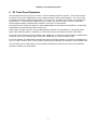
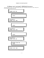
3.5 Alarms
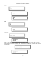
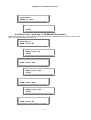
B
Network
D
Loop-1
A
Master
F
Slave
LINE
Loop--2
C
E
Figure 3- 1 Status and Performance Reference Points
3-1
DTE
Customer
Chapter 3 Operation
The definition of the alarms is as follows. Each of the detection point is key to the diagram below.
Table 3 - 1 E1 version with two LOOPs
Alarm Type
Detect
-ion
Threshold
Description
Point
LOS, MASTER-LOOP1
B
None
Master Loop-1 Loss of signal/ LOSW*
LOS, MASTER-LOOP2
C
None
Master Loop-2 Loss of signal/ LOSW*
LOS, SLAVE-LOOP1
D
None
Slave Loop-1 Loss of signal/ LOSW*
LOS, SLAVE-LOOP2
E
None
Slave Loop-2 Loss of signal/ LOSW*
LOS/LOF, MASTER-E1
A
None
Master E1 Line Loss of signal or loss of framing
LOS/LOF, SLAVE-E1
F
None
Slave E1 Line Loss of signal or loss of framing
ES15M, MASTER-LOOP1
B
1-900 (default 1)
Master Loop-1 Error Second in current 15-minute
interval
ES15M, MASTER-LOOP2
C
1-900 (default 1)
Master Loop-2 Error Second in current 15-minute
interval
ES15M, SLAVE-LOOP1
D
1-900 (default 1)
Slave Loop-1 Error Second in current 15-minute interval
ES15M, SLAVE-LOOP2
E
1-900 (default 1)
Slave Loop-2 Error Second in current 15-minute interval
ES15M, MASTER-E1
A
1-900 (default 1)
Master E1 Line Error Second in current 15-minute
interval
ES15M, SLAVE-E1
F
1-900 (default 1)
Master E1 Line Error Second in current 15-minute
interval
SES15M, MASTER-LOOP1 B
1-900 (default 1)
Master Loop-1 Severely Error Second in current 15minute interval
SES15M, MASTER-LOOP2 C
1-900 (default 1)
Master Loop-2 Severely Error Second in current 15minute interval
SES15M, SLAVE-LOOP1
D
1-900 (default 1)
Slave Loop-1 Severely Error Second in current 15minute interval
SES15M, SLAVE-LOOP2
E
1-900 (default 1)
Slave Loop-2 Severely Error Second in current 15minute interval
SES15M, MASTER-E1
A
1-900 (default 1)
Master E1 Line Severely Error Second in current 15minute interval
SES15M, SLAVE-E1
F
1-900 (default 1)
Slave E1 Line Severely Error Second in current 15minute interval
ES24H, MASTER-LOOP1
B
1-65535 (default 1) Master Loop-1 Error Second in current 24 hours
ES24H, MASTER-LOOP2
C
1-65535 (default 1) Master Loop-2 Error Second in current 24 hours
ES24H, SLAVE-LOOP1
D
1-65535 (default 1) Slave Loop-1 Error Second in current 24 hours
ES24H, SLAVE-LOOP2
E
1-65535 (default 1) Slave Loop-2 Error Second in current 24 hours
ES24H, MASTER-E1
A
1-65535 (default 1) Master E1 Line Error Second in current 24 hours
ES24H, SLAVE-E1
F
1-65535 (default 1) Slave E1 Line Error Second in current 24 hours
SES24H, MASTER-LOOP1 B
1-65535 (default 1) Master Loop-1 Severely Error Second in current 24
hours
SES24H, SLVAE-LOOP2
1-65535 (default 1) Master Loop-2 Severely Error Second in current 24
hours
C
SES24H, MASTER-LOOP1 D
1-65535 (default 1) Slave Loop-1 Severely Error Second in current 24 hours
SES24H, SLAVE-LOOP2
E
1-65535 (default 1) Slave Loop-2 Severely Error Second in current 24 hours
SES24H, MASTER-E1
A
1-65535 (default 1) Master E1 Line Severely Error Second in current 24
hours
SES24H, SLAVE-E1
F
1-65535 (default 1) Slave E1 Line Severely Error Second in current 24 hours
3-2
Chapter 3 Operation
LOW NOISE MARGIN
B, C, D, E
0 – 60 (default 1)
Signal Noise Margin of Line
* Loss of Synchronous Word
The alarm queue can be obtained for both master and slave, which contains the time stamp and alarm type
of the last 40 alarms. Alarm history and alarm status registers are also kept, which are used to track the
alarm count. Each alarm can be individually enabled or disabled. When disabled, no action is taken upon
detection of an alarm. When enabled, the alarm counter increases by one for each alarm type. Alarm is
triggered when an alarm occurs or when the counter exceeds a set threshold.
3.6 Reports
From the master unit, by use of the LCD front panel, or a terminal connected to the Loop-H, the current
status of both master and slave units can be obtained. Status includes sync status of loop1, loop2, and one
of V.35, E1, or T1.
Also, by use of the terminal connected to the master, the performance report of both master and slave unit
can be obtained. Performance reports contain performance parameters recorded in 15-minute intervals for
the past 24 hours. Reports for each of the following parameters are available.
Table 3- 1 Performance Parameter
Performance Parameter
ES
SES
UAS
Description
Error Seconds
Severe Error Second
Unavailable Second
3.7 Date and Time
The Loop-H 3300 is equipped with an RTC (real time clock). The date and time is set to Zulu+8 at the
factory. Users can change the date and time. The RTC has a self-contained battery with a power-off life of
10 years from shipment.
3.8 Front Panel Lock
Normally, front panel can provide configuration change capability. If the "menu lock" is enabled,
configuration change is allowed only with a password. Without a password, users still can operate front
panel to obtain the configuration information and line status. However, no modification is allowed. This
function is linked with the password enable function of the terminal operation; i.e. the password enabled in
the terminal operation will lock the front panel as well.
When enabled, for some operations, users have to enter the password correctly. Use left or right arrows (<>)
to pick the character. There are 66 characters to choose from. Password modification can only be done
using terminal operation. The default is unlocked.
3-3
Chapter 3 Operation
3.9 LED Indicators
The front panel of each Loop-H has 12 LEDs. One is to indicate presence of power. The next four shows
the status of one or two 16PAM loops, a test condition indicator, and an alarm indicator. The next 7 LEDs
are defined according to whether the interface is V.35 or E1/T1. One LED is to indicate V.35, another is to
indicate E1/T1. If V.35, there are LEDs for RTS, TD, TEST, RD, and CLK-LOSS. If E1/T1, three LEDs
indicate bipolar violation, RAI/AIS and a sync or test indicator.
Front Panel for E1:
TM
Loop-H
ESC
G.shdsl
G.shdsl
SYNC/TEST
RAI/AIS
BPV
E1
ENTER
POWER
LOOP1
LOOP2
TEST
ALARM
DTE
RTS
TD
TEST
RD
CLK-LOSS
Front Panel for T1:
TM
Loop-H
ESC
G.shdsl
G.shdsl
SYNC/TEST
YEL/AIS
BPV
T1
ENTER
POWER
LOOP1
LOOP2
TEST
ALARM
DTE
RTS
TD
TEST
RD
Figure 3- 2 LED Front Panel
3-4
CLK-LOSS
Chapter 4 Maintenance
4 Maintenance
Maintenance of the Loop-H 3300 system is aided by the self-test capability of the units and by the loopback
facilities.
4.1 Self test
As each element is powered up, a self-test is automatically performed to check for internal operations. At
system power up, a complete self-test routine is run to check all system elements, including the metallic
loops used for the 16PAM facility. System power up means that all elements, including master and slaves,
are powered up. The front panel LEDs, LCD panel, and the terminal screen can all be used to obtain the
general performance of the system.
Table 4- 1 LED Indication for Normal Operation
LED
Color
Indication
Power
Green
Off
Power on and operational
Power off, self-test failure, or during initialization
Loop 1
Green
Flashing Green
Off
Loop 1 is in sync
Loop 1 synchronization is in progress
Loop 1 is not sync or not existed
x Loop 2
D
S
L Test
Green
Flashing Green
Off
Loop 2 is in sync
Loop 2 synchronization is in progress
Loop 2 is not sync or not existed
Off
Amber
Normal
xDSL line-side test is in progress
Alarm
Off
Red
Normal
Alarm happened
E1
Green
Off
E1 Card is present
E1 Card is not present
E1
SYNC/TEST Green
Flashing Green
Off
E1 Line frame is sync
E1 Line-side test is in progress
E1 Line frame is unsync
RAI/AIS
Off
Amber
Flashing Amber
Normal
Receive Remote Alarm Indication from E1 line
Receive AIS from E1 line
BPV
Off
Red
Normal
E1 line has bipolar
T1
Green
Off
T1 Card is present
T1 Card is not present
SYNC/TEST Green
T1
Flashing Green
Off
T1 Line frame is sync
T1 Line-side test is in progress
T1 Line frame is unsync
YEL/AIS
Off
Amber
Flashing Amber
Normal
Receive Yellow Alarm from T1 line
Receive AIS from T1 line
BPV
Off
Red
Normal
T1 line has bipolar
4-1
Chapter 4 Maintenance
4.2 Diagnostics
A 20-bit register QRSS (quasi-random signal sequence) is used in Loop-H 3300 as an aid in trouble location.
This is used in conjunction with various loopbacks to isolate faults. In both front panel and terminal operation,
user may utilize ‘ < ‘ key to reset error counter. To choose Off under BERT to terminate the BERT test.
4.3 Loopbacks
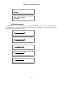
Trouble isolation of the entire xDSL system is facilitated by the use of loopbacks. By determining where one
loopback is successful and another is not, the repair personnel can isolate the fault to a particular line or
equipment. Loopbacks can be towards the network, or towards the customer.
NOTE: User have to terminate the current loopback function before using other loopback functions. For
example, if you wants to change xDSL to LINE loopback as xDSL to DTE loopback, you must
terminate the xDSL to LINE loopback first.
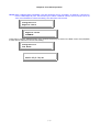
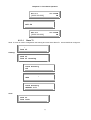
Loopbacks are activated from (a) the front panel of the units, (b) a terminal attached to the units. Only the
master can activate a loopback remotely. Figure 5 illustrates the various loopbacks.
E1: 1032 - 200 Kbps
T1: 776 - 200 Kbps
Network
Loop-H 3300
Master
Loop-H 3300
Slave
Master Network Loopback
Customer
Slave Network Loopback
E1: 1032 - 200 Kbps
T1: 776 - 200 Kbps
Network
Loop-H 3300
Master
Loop-H 3300
Slave
Master Customer Loopback
Network
Loop-H 3300
Master
Customer
Slave Customer Loopback
E1: 2056 - 200 Kbps
T1: 1544 - 200 Kbps
Master Customer Loopback
Loop-H 3300
Slave
Customer
Slave Customer Loopback
E1: 2056 - 200 Kbps
T1: 1544 - 200 Kbps
Network
Loop-H 3300
Master
Loop-H 3300
Slave
Master Customer Loopback
Customer
Slave Customer Loopback
NOTE: Both network and customer site could be independently E1, T1 or DTE.
Figure 4- 1 Loopbacks available
4.3.1 Loopbacks Toward Network
Loopbacks toward the network take signals originating from the network transmit pair and send them back to
the network receive pair. The various loopbacks are illustrated in the upper diagram of Figure 4-1.
4.3.2 Loopbacks Toward Customer
Loopbacks toward the customer take signals originating from the customer transmit pair and send them back
to the customer receive pair.
4-2
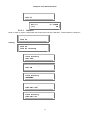
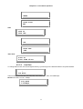
Chapter 5 Front Panel Operation
5 E1 Front Panel Operation
The front panel of each Loop-H has 12 LEDs. One is to indicate presence of power. The next four shows
the status of one or two 16PAM loops, a test condition indicator, and an alarm indicator. The next 7 LEDs
are defined according to whether the interface is V.35 or E1/T1. One LED is to indicate V.35, another is to
indicate E1/T1. If V.35, there are LEDs for RTS, TD, TEST, RD, and CLK-LOSS. If E1/T1, three LEDs
indicate bipolar violation, RAI/AIS alarm conditions, and a sync or test indicator.
A terminal must be used for the display of other detailed status and to initiate local loopbacks. Furthermore,
configuration must be performed at the master end.
Power LED is a single color LED. Loop-H 3300 performs self-test on the powering up. The power LED is
green if the self-test is passed. Otherwise, it is off and the rest of LCD shows the cause of the failure.
Loop1 and Loop2 indicators show the status of the 16PAM line. It is green if synchronization is established. It
is off when sync is lost. Flashing green shows the 16PAM loop is in synchronization mode.
For E1/T1 interface, the SYNC/TEST indicates the status of the DS1 interface. It is green if the interface is in
sync. It is off if it is loss of sync or loss of frame. Flashing green indicates the interface is under loopback test.
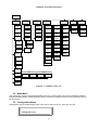
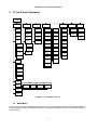
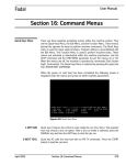
The LCD menu tree is shown below. By successively selecting the menu item at each level, the desired
operation or display can be obtained.
5-1
Chapter 5 Front Panel Operation
Main Menu
Alarm
Configuration
Diagnostics
Status
Performance
Informance
Miscellaneous
xDSL
Mode
Alarm
Queue
xDSL
Loopback
Reset
Performance
Master
Loop1 ES
M-Loop1
Status
Software
Version
Date
Clock
Source
Alarm
History
E1
Loopback
Master
Loop1 ES
Master
Loop1 SES
S-Loop1
Status
Serial
Number
Time
Slave
Clock
Alarm
Clear
Slave
Loopback
Master
Loop1 SES
Master
Loop1
UAS
M-Loop2
Status
E1
Alarm
Setup
BERT
Master
Loop1
UAS
Master
Loop2 ES
S-Loop2
Status
Framing
Alarm
Type
Master
Loop2 ES
Master
Loop2 SES
M-E1 TxStatus
Code
Alarm
Threshol
d
Master
Loop2 SES
Master
Loop2
UAS
M-E1 RxStatus
Master
Loop2
UAS
Master E1
ES
S-E1 TxStatus
Master E1
ES
Master E1
SES
S-E1 RxStatus
Framing
Master E1
SES
Master E1
UAS
Code
Master E1
UAS
Time Slot
Alarm
Cut Off
Slave E1
Lock Front
Panel
Time Slot
Line
Rate
1 Pair
Loop
Num
Loop-One
2 Pairs
Loop-Two
Two-Loops
One + One
Baud
Rate
Adaptive
Rate
Figure 5- 1 LCD Menu Tree – E1
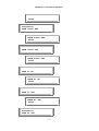
5.1 Main Menu
The main menu, the first menu displayed after power up, is shown below, where the underlined character
indicates flashing display, meaning that this item is selected by default unless the user presses the right or
left arrow keys.
5.2 Configuration Menu
Configuration group includes xDSL mode, clock source, slave clock, E1, slave E1, line rate.
xDSL-E1-MASTER
Configuration
5-2
Chapter 5 Front Panel Operation
5.2.1 xDSL Mode
Mode can be master or slave. For each pair of connected Loop-H, one must be master and the other slave.
The Slave mode Loop-H can only be synchronized to the master through the line. To change the mode to
master or slave, use left and right arrow key cycle through to the desired selection and press ENTER. The
current selection is indicated by “*”.
Configuration
xDSL Mode
xDSL Mode
*MASTER
xDSL Mode
SLAVE
5.2.2 Clock Source
Clock source group includes LINE, INTERNAL, E1 and Slave Clock. Press ENTER to change the clock
source to LINE, INTERNAL, E1, and Slave Clock. For the mode selected, if an invalid clock is selected, the
command will be ignored.
Configuration
Clock Source
Clock Source
*LINE
Clock Source
INTERNAL
Clock Source
E1
5-3
Chapter 5 Front Panel Operation
Configuration
Slave Clock
Slave Clock
*LINE
Slave Clock
INTERNAL
Slave Clock
E1
5.2.3 E1 Menu
E1 menu is used to configuration the framing and code of the E1. Press ENTER to configure it.
Configuration
E1
Framing:
E1
Framing
Framing
*CRC-OFF
Framing
*CRC-ON
Framing
*CAS-CRC-OFF
Framing
*CAS-CRC-ON
5-4
Chapter 5 Front Panel Operation
Framing
UNFRAME
Code:
E1
Code
Code
*HDB3
Time Slots:
E1
Time Slots
Time Slots
TS00-09
Here "i" (eye, idle) m eans T S that cannot be used for transmission of any data; "1" (one)
means active T S carrying custom er data; "X" means TS available for customer data, but not
in active use.
TS00-09
*[iX11ii1111]
32:2048K
OK
Time Slots
TS10-19
TS10-19
*[11llllllll]
31:1984K
OK
Time Slots
TS20-29
TS20-29
*[llllllllll]
5-5
31:1984K
OK
Chapter 5 Front Panel Operation
Time Slots
TS30-31
TS30-31
*[ll]
5.2.3.1
31:1984K
OK
Slave E1
Slave E1 menu is used to configuration the framing and code of the Slave/E1. Press ENTER to configure it.
Configuration
Slave E1
Framing:
Slave E1
Slave E1 Framing
Slave Framing
*CRC-OFF
Slave Framing
*CRC-ON
Slave Framing
*UNFRAME
Slave Framing
*CAS-CRC-OFF
Slave Framing
*CAS-CRC-ON
5-6
Chapter 5 Front Panel Operation
Code:
Slave E1
Slave Code
Slave Code
*HDB3
Time Slots:
Slave E1
Slave Time Slots
5.2.3.2
Line Rate
To change the line rate, use left and right arrow key cycle through to the desired selection and press ENTER.
Configuration
Line Rate
The line rate choices are 200, 264, 392, 520, 776, 1032, 1160, 1544, and 2056 Kbps.
NOTE: Each rate is n x 64 + 8 Kbps.
Line Rate
*1160Kbps
5.2.3.3
Loop Number
Under Configuration menu, use arrow keys to select Loop Num option, which supports 1 pair and 2 pairs.
Configuration
Loop Num
Press ENTER from the above menu. Use arrow keys to select one desired number from these options: Two
Loops, Loop-One, Loop-Two, and One + One. Then press ENTER after finishing the selection. The current
selection will be highlighted by an asterisk (*).
When 1 pair is used, user can select Loop-One or Loop-Two as the active Loop.
1 pair: Loop-One
Configuration
Loop Num
5-7
Chapter 5 Front Panel Operation
The following LCD means Loop-One is active now.
Loop Num
*Loop-One
1 pair: Loop-Two
Configuration
Loop Num
The following LCD means Loop-Two is active now.
Loop Num
*Loop-Two
When 2 pairs are used, user can select Two Loops used together or One + One protection.
2 pairs: Two-Loops
Configuration
Loop Num
The following LCD means two loops are active now.
Loop Num
*Two Loops
2 pairs: One + One
Configuration
Loop Num
The following LCD means 1 + 1 protection is available now.
Loop Num
*One + One
5-8
Chapter 5 Front Panel Operation
5.2.3.4
Baud Rate
Under Configuration menu, use arrow keys to select Baud Rate option. Two options, 9600 or 19200 are
available. Move the cursor to the desired option, then press ENTER to confirm the selection. The current
selection will be highlighted by an asterisk (*).
Configuration
Baud Rate
Baud Rate
*9600
Baud Rate
19200
5.2.3.5
Adaptive Line Rate
Under Configuration menu, use arrow keys to select Adaptive Rate option, press ENTER to enter into its
submenu. This menu is used to enable or disable adaptive line rate.
NOTE: When "Adaptive Rate" is enabled, users are not allowed to set up "Line Rate". See also blew LCD
screens.
Configuration
Adaptive Rate
Adaptive Rate
*ENABLE
Press ESC to exit the "Adaptive Rate" menu, and use arrow keys to select "Line Rate" menu. Press ENTER
to enter into its submenu to display the current line rate setting.
Configuration
Line Rate
Line Rate:1608K
Nx64:25
5-9
Chapter 5 Front Panel Operation
NOTE: When "Adaptive Rate" is disabled, users are allowed to set up "Line Rate". An asterisk (*) will show in
front of "NX64:25(3-32) OK". Use arrow keys to select a desired number, then move the cursor at
"OK". Press ENTER to confirm the setting. See also blew LCD screens.
Configuration
Adaptive Rate
Adaptive Rate
*DISABLE
Press ESC to exit the "Adaptive Rate" menu, and use arrow keys to select "Line Rate" menu. Press ENTER
to enter into its submenu to do line rate setting.
Configuration
Line Rate
Line Rate:1608K
*Nx64:25(3-32)OK
5-10
Chapter 5 Front Panel Operation
5.3 Alarm
The alarm menu allows the user to view the latest alarm. Alarm group includes Alarm Queue, Alarm History,
Alarm Clear, Alarm Setup, and Alarm Cut Off. Alarm menu is used to view alarm queue and alarm history, to
clear alarm queue, and alarm history, alarm cut off, as well as setup alarm threshold, etc. as in the following
paragraph.
xDSL-E1-MASTER
Alarm
5.3.1 Alarm Queue
The alarm queue is a consolidation of the latest 40 alarms from all of the Loop-H plug-in cards. When the
queue is full, the earliest one is replaced by the latest one.The user can select one of latest alarms.
Alarm
Alarm Queue
When the item QUEUE is first selected, the latest alarm will be displayed.
01 LOS,M-L1
08:09:10 04/16
21 SES24H, M-L1
08:09:10 04/16
5.3.2 Alarm History
Alarm History menu is used to view alarm history. Under Alarm menu, use left or right key to select Alarm
History menu.
Alarm
Alarm History
LOS, M-L1
DISABLE 0
LOS, M-L1
ENABLE ALM 1
5-11
Chapter 5 Front Panel Operation
SES24H, M-L1
DISABLE 0
SES24H, M-L1
ENABLE 0
Alarm History menu shows the alarm history of various type of alarm. To view alarm history, use left or right
arrow key to cycle through and the alarm history is shown.
5.3.3 Alarm Clear
Alarm Clear menu is used to clear alarm queue and history. Under Alarm menu, use left or right key to select
Alarm Clear menu.
Alarm
Alarm Clear
At this menu, press ENTER to confirm clear alarm queue and history. Otherwise press ESC to exit without
any action.
Alarm
Confirm ?
Alarm Clear
Clearing...OK
5.3.4 Alarm Setup
Alarm Setup menu is used to set up the threshold level of each alarm type. Some type of alarm does not
have threshold level. Under Alarm menu, use left or right key to select Alarm Setup menu.
Alarm
Alarm Setup
5.3.4.1
Alarm Type
Alarm Type menu is used to disable or enable the alarm type of M-L1.
Alarm Setup
Alarm Type
Alarm Type
LOS,M-L1
5-12
Chapter 5 Front Panel Operation
LOS,M-L1
*DISABLE
LOS,M-L1
ENABLE
5.3.4.2
Alarm Threshold
To setup ES, UAS, OS are similar. For example, to setup ES15M, M-L1 threshold level and press ENTER.
Alarm Setup
Alarm Threshold
Threshold
LOS, M-L1
ES15M, M-L1
*001 (1-900)
OK
Threshold
SES24H, M-L1
SES24H, M-L1
*00001
OK
To change threshold level of ES (or others), use left or right arrow key to cycle through to the digit position,
and press ENTER key to cycle through the number. This operation must be concluded by moving left or right
arrow key to OK position and press ENTER to enable the changes.
5.3.5 Alarm Cut Off
To cut off alarm, enter "A". A prompt asking for action is shown.
Alarm
Alarm Cut Off
Alarm Cut Off
Confirm?
5-13
Chapter 5 Front Panel Operation
Alarm Cut Off
AC0...OK
5.4 Diagnostics Menu
Diagnostics group includes xDSL Loopback, E1 Loopback, Slave Loopback, BERT. If a xDSL loopback is in
session, the front panel SYNC/TEST LED flashes green. If a E1 Loopback is in session, the front panel
TEST LED flashes green.
xDSL-E1-MASTER
Diagnostics
5.4.1 xDSL Loopback Menu
Loopback menus are used to control near end xDSL line side loopback operation such TO-E1 and TO-LINE
loopback test. Under Diagnostics menu, use left or right key to select xDSL Loopback menu.
Diagnostics
xDSL Loopback
xDSL Loopback
*OFF
xDSL Loopback
TO-E1
xDSL Loopback
TO-LINE
To select a loopback type, use left or right arrow key to cycle through to a desired selection and press
ENTER. Select OFF to end the loopback test.
5.4.2 E1 Loopback Menu
E1 loopback menu used to control E1 loopback. Under Diagnostics menu, use left or right key to select E1
Loopback menu.
Diagnostics
E1 Loopback
To select a loopback type, use left or right arrow key to cycle through to a desired selection and press
ENTER. Select OFF to end the loopback test.
5-14
Chapter 5 Front Panel Operation
E1 Loopback
*OFF
E1 Loopback
TO-E1
E1 Loopback
TO-LINE
5.4.3 Slave Loopback Menu
Slave Loopback is used to activate slave loopback test. A proprietary message is sent to request the remote
Loop-H to perform Line or E1 loopback. Under Diagnostics menu, use left or right key to select Slave
Loopback menu.
Diagnostics
Slave Loopback
Slave Loopback
*OFF
Slave Loopback
E1-TO-LINE
Slave Loopback
xDSL-TO-LINE
Slave Loopback
E1-TO-E1
Slave Loopback
xDSL-TO-E1
To activate slave loopback, use left or right arrow key cycle through to a desired selection and press ENTER.
To deactivate slave loopback, select OFF.
5-15
Chapter 5 Front Panel Operation
5.4.4 BERT
After the loopback is in place, BERT test can be performed. Select BERT menu to start the bit error rate test.
Diagnostics
BERT
BERT
*OFF
BERT
QRSS
5.5 Performance
PERF shows the performance information about the Reset Performance, Master Loop-1, Loop-2, and E1
Performance, Slave Loop-1, Loop-2, and E1 Performance. The current 24 hours data are recorded in
performance register.
xDSL-E1-MASTER
Performance
5.5.1 Reset Performance
Reset Performance menu is used to clear all Loop-H performance status report. Under Performance menu,
use left or right key to select Reset Performance menu.
At this menu, press ENTER to confirm clear all performance status report. Otherwise press ESC to exit
without any action.
Performance
Reset Perf.
Reset Perf.
Corfirm?
5-16
Chapter 5 Front Panel Operation
5.5.2 Master Loop1, Loop2 and E1 ES/SES/UAS Performance
Under Performance menu, you could select ES, SES, and UAS Performance menu for Loop1, Loop2, and
E1 by using left and right arrow keys.
Performance
MASTER LOOP1 ES
MASTER LOOP1 ES
65535
Performance
MASTER LOOP1 SES
MASTER LOOP1 SES
65535
Performance
MASTER LOOP1 UAS
MASTER LOOP1 UAS
65535
Performance
MASTER LOOP2 ES
MASTER LOOP2 ES
65535
Performance
MASTER LOOP2 SES
5-17
Chapter 5 Front Panel Operation
MASTER LOOP2 SES
65535
Performance
MASTER LOOP2 UAS
MASTER LOOP2 UAS
65535
Performance
MASTER E1 ES
MASTER E1 ES
65535
Performance
MASTER E1 SES
MASTER E1 SES
65535
Performance
MASTER E1 UAS
MASTER E1 UAS
65535
5-18
Chapter 5 Front Panel Operation
5.5.3 Slave Loop1, Loop2 and E1 ES/SES/UAS Performance
Under Performance menu, you could select slave ES, SES, and UAS Performance menu for Loop1, Loop2,
and E1 by using left and right arrow keys.
Performance
SLAVE LOOP1 ES
SLAVE LOOP1 ES
65535
Performance
SLAVE LOOP1 SES
SLAVE LOOP1 SES
65535
Performance
SLAVE LOOP1 UAS
SLAVE LOOP1 UAS
65535
Performance
SLAVE LOOP2 ES
SLAVE LOOP2 ES
65535
Performance
SLAVE LOOP2 SES
5-19
Chapter 5 Front Panel Operation
SLAVE LOOP2 SES
65535
Performance
SLAVE LOOP2 UAS
SLAVE LOOP2 UAS
65535
Performance
SLAVE E1 ES
SLAVE E1 ES
65535
Performance
SLAVE E1 SES
SLAVE E1 SES
65535
Performance
SLAVE E1 UAS
SLAVE E1 UAS
65535
5-20
Chapter 5 Front Panel Operation
5.6 Status
STATUS is to show the various statuses of the local or slave xDSL loops (LINE) and local or slave E1.
The status is shown as normal if the interface is not experienced any problem. Otherwise, the problem is
shown. The possible problems are LOS (loss of signal), LOF (loss of framing), RAI (receive remote alarm
information), AIS (receive Alarm indication).
xDSL-E1-MASTER
Status
Status
M-LOOP1 Status
M-LOOP1 Status
SYNC
Status
S-LOOP1 Status
S-LOOP1 Status
SYNC
Status
M-LOOP2 Status
M-LOOP2 Status
SYNC
Status
S-LOOP2 Status
S-LOOP2 Status
SYNC
5-21
Chapter 5 Front Panel Operation
Status
M-E1 Tx-Status
M-E1 Tx-Status
*TxAIS TxRAI
Status
M-E1 Rx-Status
M-E1 Rx-Status
*LOS
*LOF
Status
S-E1 Tx-Status
S-E1 Tx-Status
*TxAIS TxRAI
Status
S-E1 Rx-Status
S-E1 Rx-Status
RxAIS *RxRAI
S-E1 Rx-Status
*LOS
*LOF
5-22
Chapter 5 Front Panel Operation
5.7 Information
The Information item provides software and hardware version number, and serial number of the Loop-H unit.
Modifications are not allowed.
xDSL-E1-MASTER
Information
Information
S/W Version
S/W Version
V1.10 05/25/1998
Information
Serial number
Serial Number
8888
5-23
Chapter 5 Front Panel Operation
5.8 Miscellaneous
The miscellaneous group includes the date and information items.
To modify the date and time, first move cursor to the date and time digit on the first-line. Press ENTER.
Then move cursor to the desired number on the second line. Press ENTER. Move the cursor to YES, then
ENTER, to start the new date. Use ESCAPE key to abort the changes.
The system information includes the software release version and date, and the serial number.
xDSL-E1-MASTER
Miscellaneous
Miscellaneous
Date
Date
05/25/1998
OK
Miscellaneous
Time
Time
15:40:30
OK
5.8.1 Lock Front Panel
Lock menu is used to control LCD panel operation. Normally, front panel can provide configuration change
capability. If the "menu lock" is enabled, configuration change is allowed only with a password. Without a
password, users still can operate front panel to obtain the configuration information and line status. However,
no modification is allowed. This function is linked with the password enable function of the terminal operation,
i.e. the password enabled in the terminal operation will lock the front panel as well.
When enabled, for some operations, users have to enter the password correctly. Use left or right arrows (<>)
to pick the character. There are 66 characters to choose from. Password modification can only be done
using terminal operation. The default password is LOOP.
Miscellaneous
Lock front panel
5-24
Chapter 5 Front Panel Operation
Lock front panel
*ENABLE
Lock front panel
*DISABLE
5.8.2 Password Setup
To enable the password, select "ENABLE". The previous entered password is used. The password itself is
not case sensitive. If you want to select your own password, select "CHANGE". A prompt asking the original
password and new password are shown.
PW:
OK
0123456789ABCDEF
PW:
OK
GHIJKLMNOPQRSTUV
PW:
OK
WXYZ!”#$%&’()*+,
PW:
OK
-./:;<=>?@[]^_`{
PW:
|}
OK
5-25
Chapter 6 T1 Front Panel Operation
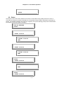
6 T1 Front Panel Operation
Main Menu
Configuration
Alarm
Diagnostics
Status
Performance
Informance
Miscellaneous
xDSL
Mode
Alarm
Queue
xDSL
Loopback
Reset
Performance
Master
Loop1 ES
M-Loop1
Status
Software
Version
Date
Clock
Source
Alarm
History
T1
Loopback
Master
Loop1 ES
Master
Loop1 SES
S-Loop1
Status
Serial
Number
Time
Slave
Clock
Alarm
Clear
Slave
Loopback
Master
Loop1 SES
Master
Loop1
UAS
M-Loop2
Status
T1
Alarm
Setup
BERT
Master
Loop1
UAS
Master
Loop2 ES
S-Loop2
Status
Alarm
Type
Master
Loop2 ES
Master
Loop2 SES
M-E1 TxStatus
Alarm
Master
Loop2 SES
Master
Loop2
UAS
M-E1 RxStatus
Master
Loop2
UAS
Master T1
ES
S-E1 TxStatus
Master T1
ES
Master T1
SES
S-E1 RxStatus
Master T1
SES
Master T1
UAS
Framing
Code
CAS
Threshold
Alarm
Cut Off
Time Slot
Slave T1
Lock Front
Panel
Master T1
UAS
Framing
Code
CAS
Time Slot
Line
Rate
1 Pair
Loop
Num
Loop-One
2 Pairs
Loop-Two
Two-Loops
One + One
Baud
Rate
Adaptive
Rate
Figure 6- 1 LCD Menu Tree – T1
6.1 Main Menu
The main menu, the first menu displayed after power up, is shown below, where the underlined character
indicates flashing display, meaning that this item is selected by default unless the user presses the right or
left arrow keys.
6-1
Chapter 6 T1 Front Panel Operation
6.2 Configuration Menu
Configuration group includes xDSL mode, clock source, slave clock, T1, slave T1, line rate.
xDSL-T1-MASTER
Configuration
6.2.1 xDSL Mode
Mode can be master or slave. For each pair of connected Loop-H, one must be master and the other slave.
The Slave mode Loop-H can only be synchronized to the master through the line. To change the mode to
master or slave, use left and right arrow key cycle through to the desired selection and press ENTER. The
current selection is indicated by “*”.
Configuration
xDSL Mode
xDSL Mode
*MASTER
xDSL Mode
SLAVE
6.2.2 Clock Source
Clock source group includes LINE, INTERNAL, T1 and Slave Clock. Press ENTER to change the clock
source to LINE, INTERNAL, T1, and Slave Clock. For the mode selected, if an invalid clock is selected, the
command will be ignored.
Configuration
Clock Source
Clock Source
*LINE
Clock Source
INTERNAL
Clock Source
T1
6-2
Chapter 6 T1 Front Panel Operation
Configuration
Slave Clock
Slave Clock
*LINE
Slave Clock
INTERNAL
Slave Clock
T1
6.2.3 T1 Menu
T1 menu is used to configuration the framing and code of the T1. Press ENTER to configure it.
Configuration
T1
Framing:
T1
Framing
Framing
*D4
Framing
*ESF
Framing
*ESF&T1.403
6-3
Chapter 6 T1 Front Panel Operation
Code:
T1
Code
Code
*B8ZS
Code
AMI
CAS:
T1
CAS
CAS
*OFF
Time Slots:
T1
Time Slots
Time Slots
TS00-09
Here "i" (eye, idle) m eans T S that cannot be used for transmission of any data; "1" (one)
means active T S carrying custom er data; "X" means TS available for customer data, but not
in active use.
TS00-09
*[1ii11X1111]
Time Slots
TS10-19
6-4
24:1536K
OK
Chapter 6 T1 Front Panel Operation
TS10-19
*[11llllllll]
24:1536K
OK
Time Slots
TS21-24
TS21-24
*[llllllllll]
6.2.3.1
24:1536K
OK
Slave T1
Slave T1 menu is used to configuration the framing and code of the Slave/T1. Press ENTER to configure it.
Configuration
Slave T1
Framing:
Slave T1
Slave T1 Framing
Slave Framing
*D4
Slave Framing
*ESF
Slave Framing
*ESF&T1.403
Code
Slave T1
Slave Code
6-5
Chapter 6 T1 Front Panel Operation
Slave Code
*B8ZS
Slave Code
AMI
CAS:
Slave T1
Slave CAS
Slave CAS
*ON
Slave CAS
OFF
Time Slots:
Slave T1
Slave Time Slots
6.2.3.2
Line Rate
To change the line rate, use left and right arrow key cycle through to the desired selection and press ENTER.
Configuration
Line Rate
The line rate choices are 200, 264, 392, 520, 776, 1032, 1160, 1544, and 2056 Kbps.
NOTE: Each rate is n x 64 + 8 Kbps.
Line Rate
*1160Kbps
6-6
Chapter 6 T1 Front Panel Operation
6.2.3.3
Loop Number
Under Configuration menu, use arrow keys to select Loop Num option, which supports 1 pair and 2 pairs.
Configuration
Loop Num
Press ENTER from the above menu. Use arrow keys to select one desired number from these options: Two
Loops, Loop-One, Loop-Two, and One + One. Then press ENTER after finishing the selection. The current
selection will be highlighted by an asterisk (*).
When 1 pair is used, user can select Loop-One or Loop-Two as the active Loop.
1 pair: Loop-One
Configuration
Loop Num
The following LCD means Loop-One is active now.
Loop Num
*Loop-One
1 pair: Loop-Two
Configuration
Loop Num
The following LCD means Loop-Two is active now.
Loop Num
*Loop-Two
When 2 pairs are used, user can select Two Loops used together or One + One protection.
2 pairs: Two-Loops
Configuration
Loop Num
The following LCD means two loops are active now.
Loop Num
*Two Loops
6-7
Chapter 6 T1 Front Panel Operation
2 pairs: One + One
Configuration
Loop Num
The following LCD means 1 + 1 protection is available now.
Loop Num
*One + One
6.2.3.4
Baud Rate
Under Configuration menu, use arrow keys to select Baud Rate option. Two options, 9600 or 19200 are
available. Move the cursor to the desired option, then press ENTER to confirm the selection. The current
selection will be highlighted by an asterisk (*).
Configuration
Baud Rate
Baud Rate
*9600
Baud Rate
19200
6.2.3.5
Adaptive Line Rate
Under Configuration menu, use arrow keys to select Adaptive Rate option, press ENTER to enter into its
submenu. This menu is used to enable or disable adaptive line rate.
NOTE: When "Adaptive Rate" is enabled, users are not allowed to set up "Line Rate". See also blew LCD
screens.
Configuration
Adaptive Rate
Adaptive Rate
*ENABLE
6-8
Chapter 6 T1 Front Panel Operation
Press ESC to exit the "Adaptive Rate" menu, and use arrow keys to select "Line Rate" menu. Press ENTER
to enter into its submenu to display the current line rate setting.
Configuration
Line Rate
Line Rate:1608K
Nx64:25
NOTE: When "Adaptive Rate" is disabled, users are allowed to set up "Line Rate". An asterisk (*) will show in
front of "NX64:25(3-32) OK". Use arrow keys to select a desired number, then move the cursor at
"OK". Press ENTER to confirm the setting. See also blew LCD screens.
Configuration
Adaptive Rate
Adaptive Rate
*DISABLE
Press ESC to exit the "Adaptive Rate" menu, and use arrow keys to select "Line Rate" menu. Press ENTER
to enter into its submenu to do line rate setting.
Configuration
Line Rate
Line Rate:1608K
*Nx64:25(3-32)OK
6-9
Chapter 6 T1 Front Panel Operation
6.3 Alarm
The alarm menu allows the user to view the latest alarm. Alarm group includes Alarm Queue, Alarm History,
Alarm Clear, Alarm Setup, and Alarm Cut Off. Alarm menu is used to view alarm queue and alarm history, to
clear alarm queue, and alarm history, alarm cut off, as well as setup alarm threshold, etc. as in the following
paragraph.
xDSL-T1-MASTER
Alarm
6.3.1 Alarm Queue
The alarm queue is a consolidation of the latest 40 alarms from all of the Loop-H plug-in cards. When the
queue is full, the earliest one is replaced by the latest one.The user can select one of latest alarms.
Alarm
Alarm Queue
When the item QUEUE is first selected, the latest alarm will be displayed.
01 LOS,M-L1
08:09:10 04/16
21 SES24H, M-L1
08:09:10 04/16
6-10
Chapter 6 T1 Front Panel Operation
6.3.2 Alarm History
Alarm History menu is used to view alarm history. Under Alarm menu, use left or right key to select Alarm
History menu.
Alarm
Alarm History
LOS, M-L1
DISABLE 0
LOS, M-L1
ENABLE ALM 1
SES24H, M-L1
DISABLE 0
SES24H, M-L1
ENABLE 0
Alarm History menu shows the alarm history of various type of alarm. To view alarm history, use left or right
arrow key to cycle through and the alarm history is shown.
6.3.3 Alarm Clear
Alarm Clear menu is used to clear alarm queue and history. Under Alarm menu, use left or right key to select
Alarm Clear menu.
Alarm
Alarm Clear
At this menu, press ENTER to confirm clear alarm queue and history. Otherwise press ESC to exit without
any action.
Alarm
Confirm ?
Alarm Clear
Clearing...OK
6-11
Chapter 6 T1 Front Panel Operation
6.3.4 Alarm Setup
Alarm Setup menu is used to set up the threshold level of each alarm type. Some type of alarm does not
have threshold level. Under Alarm menu, use left or right key to select Alarm Setup menu.
Alarm
Alarm Setup
6.3.4.1
Alarm Type
Alarm Type menu is used to disable or enable the alarm type of M-L1.
Alarm Setup
Alarm Type
Alarm Type
LOS,M-L1
LOS,M-L1
*DISABLE
LOS,M-L1
ENABLE
6.3.4.2
Alarm Threshold
To setup ES, UAS, OS are similar. For example, to setup ES15M, M-L1 threshold level and press ENTER.
Alarm Setup
Alarm Threshold
Threshold
LOS, M-L1
ES15M, M-L1
*001 (1-900)
OK
Threshold
SES24H, M-L1
6-12
Chapter 6 T1 Front Panel Operation
SES24H, M-L1
*00001
OK
To change threshold level of ES (or others), use left or right arrow key to cycle through to the digit position,
and press ENTER key to cycle through the number. This operation must be concluded by moving left or right
arrow key to OK position and press ENTER to enable the changes.
6.3.5 Alarm Cut Off
To cut off alarm, enter "A". A prompt asking for action is shown.
Alarm
Alarm Cut Off
Alarm Cut Off
Confirm?
Alarm Cut Off
AC0...OK
6.4 Diagnostics Menu
Diagnostics group includes xDSL Loopback, T1 Loopback, Slave Loopback, BERT. If a xDSL loopback is in
session, the front panel SYNC/TEST LED flashes green. If a T1 Loopback is in session, the front panel
TEST LED flashes green.
xDSL-T1-MASTER
Diagnostics
6.4.1 xDSL Loopback Menu
Loopback menus are used to control near end xDSL line side loopback operation such TO-T1 and TO-LINE
loopback test. Under Diagnostics menu, use left or right key to select xDSL Loopback menu.
Diagnostics
xDSL Loopback
xDSL Loopback
*OFF
xDSL Loopback
TO-T1
6-13
Chapter 6 T1 Front Panel Operation
xDSL Loopback
TO-LINE
To select a loopback type, use left or right arrow key to cycle through to a desired selection and press
ENTER. Select OFF to end the loopback test.
6.4.2 T1 Loopback Menu
T1 loopback menu used to control T1 loopback. Under Diagnostics menu, use left or right key to select T1
Loopback menu.
Diagnostics
T1 Loopback
To select a loopback type, use left or right arrow key to cycle through to a desired selection and press
ENTER. Select OFF to end the loopback test.
T1 Loopback
*OFF
T1 Loopback
TO-T1
T1 Loopback
TO-LINE
6.4.3 Slave Loopback Menu
Slave Loopback is used to activate slave loopback test. A proprietary message is sent to request the remote
Loop-H to perform Line or T1 loopback. Under Diagnostics menu, use left or right key to select Slave
Loopback menu.
Diagnostics
Slave Loopback
Slave Loopback
*OFF
Slave Loopback
T1-TO-LINE
6-14
Chapter 6 T1 Front Panel Operation
Slave Loopback
xDSL-TO-LINE
Slave Loopback
T1-TO-T1
Slave Loopback
xDSL-TO-T1
To activate slave loopback, use left or right arrow key cycle through to a desired selection and press ENTER.
To deactivate slave loopback, select OFF.
6.4.4 BERT
After the loopback is in place, BERT test can be performed. Select BERT menu to start the bit error rate test.
Diagnostics
BERT
BERT
*OFF
BERT
QRSS
6.5 Performance
PERF shows the performance information about the Reset Performance, Master Loop-1, Loop-2, and T1
Performance, Slave Loop-1, Loop-2, and T1 Performance. The current 24 hours data are recorded in
performance register.
xDSL-T1-MASTER
Performance
6-15
Chapter 6 T1 Front Panel Operation
6.5.1 Reset Performance
Reset Performance menu is used to clear all Loop-H performance status report. Under Performance menu,
use left or right key to select Reset Performance menu.
At this menu, press ENTER to confirm clear all performance status report. Otherwise press ESC to exit
without any action.
Performance
Reset Perf.
Reset Perf.
Corfirm?
6.5.2 Master Loop1, Loop2 and T1 ES/SES/UAS Performance
Under Performance menu, you could select ES, SES, and UAS Performance menu for Loop1, Loop2, and
T1 by using left and right arrow keys.
Performance
MASTER LOOP1 ES
MASTER LOOP1 ES
65535
Performance
MASTER LOOP1 SES
MASTER LOOP1 SES
65535
Performance
MASTER LOOP1 UAS
MASTER LOOP1 UAS
65535
6-16
Chapter 6 T1 Front Panel Operation
Performance
MASTER LOOP2 ES
MASTER LOOP2 ES
65535
Performance
MASTER LOOP2 SES
MASTER LOOP2 SES
65535
Performance
MASTER LOOP2 UAS
MASTER LOOP2 UAS
65535
Performance
MASTER T1 ES
MASTER T1 ES
65535
Performance
MASTER T1 SES
MASTER T1 SES
65535
6-17
Chapter 6 T1 Front Panel Operation
Performance
MASTER T1 UAS
MASTER T1 UAS
65535
6.5.3 Slave Loop1, Loop2 and T1 ES/SES/UAS Performance
Under Performance menu, you could select slave ES, SES, and UAS Performance menu for Loop1, Loop2,
and T1 by using left and right arrow keys.
Performance
SLAVE LOOP1 ES
SLAVE LOOP1 ES
65535
Performance
SLAVE LOOP1 SES
SLAVE LOOP1 SES
65535
Performance
SLAVE LOOP1 UAS
SLAVE LOOP1 UAS
65535
Performance
SLAVE LOOP2 ES
6-18
Chapter 6 T1 Front Panel Operation
SLAVE LOOP2 ES
65535
Performance
SLAVE LOOP2 SES
SLAVE LOOP2 SES
65535
Performance
SLAVE LOOP2 UAS
SLAVE LOOP2 UAS
65535
Performance
SLAVE T1 ES
SLAVE T1 ES
65535
Performance
SLAVE T1 SES
SLAVE T1 SES
65535
Performance
SLAVE T1 UAS
6-19
Chapter 6 T1 Front Panel Operation
SLAVE T1 UAS
65535
6.6 Status
STATUS is to show the various statuses of the local or slave xDSL loops (LINE) and local or slave T1.
The status is shown as normal if the interface is not experienced any problem. Otherwise, the problem is
shown. The possible problems are LOS (loss of signal), LOF (loss of framing), RAI (receive remote alarm
information), AIS (receive Alarm indication).
xDSL-T1-MASTER
Status
Status
M-LOOP1 Status
M-LOOP1 Status
SYNC
Status
S-LOOP1 Status
S-LOOP1 Status
SYNC
Status
M-LOOP2 Status
M-LOOP2 Status
SYNC
Status
S-LOOP2 Status
6-20
Chapter 6 T1 Front Panel Operation
S-LOOP2 Status
SYNC
Status
M-T1 Tx-Status
M-T1 Tx-Status
*TxAIS TxRAI
Status
M-T1 Rx-Status
M-T1 Rx-Status
*LOS
*LOF
Status
S-T1 Tx-Status
S-T1 Tx-Status
*TxAIS TxRAI
Status
S-T1 Rx-Status
S-T1 Rx-Status
RxAIS *RxRAI
S-T1 Rx-Status
*LOS
*LOF
6-21
Chapter 6 T1 Front Panel Operation
6.7 Information
The Information item provides software and hardware version number, and serial number of the Loop-H unit.
Modifications are not allowed.
xDSL-T1-MASTER
Information
Information
S/W Version
S/W Version
V1.10 05/25/1998
Information
Serial number
Serial Number
8888
6.8 Miscellaneous
The miscellaneous group includes the date and information items.
To modify the date and time, first move cursor to the date and time digit on the first-line. Press ENTER.
Then move cursor to the desired number on the second line. Press ENTER. Move the cursor to YES, then
ENTER, to start the new date. Use ESCAPE key to abort the changes.
The system information includes the software release version and date, and the serial number.
xDSL-T1-MASTER
Miscellaneous
Miscellaneous
Date
Date
05/25/1998
OK
6-22
Chapter 6 T1 Front Panel Operation
Miscellaneous
Time
Time
15:40:30
OK
6.8.1 Lock Front Panel
Lock menu is used to control LCD panel operation. Normally, front panel can provide configuration change
capability. If the "menu lock" is enabled, configuration change is allowed only with a password. Without a
password, users still can operate front panel to obtain the configuration information and line status. However,
no modification is allowed. This function is linked with the password enable function of the terminal operation,
i.e. the password enabled in the terminal operation will lock the front panel as well.
When enabled, for some operations, users have to enter the password correctly. Use left or right arrows (<>)
to pick the character. There are 66 characters to choose from. Password modification can only be done
using terminal operation. The default password is LOOP.
Miscellaneous
Lock front panel
Lock front panel
*ENABLE
Lock front panel
*DISABLE
6-23
Chapter 6 T1 Front Panel Operation
6.8.2 Password Setup
To enable the password, select "ENABLE". The previous entered password is used. The password itself is
not case sensitive. If you want to select your own password, select "CHANGE". A prompt asking the original
password and new password are shown.
PW:
OK
0123456789ABCDEF
PW:
OK
GHIJKLMNOPQRSTUV
PW:
OK
WXYZ!”#$%&’()*+,
PW:
OK
-./:;<=>?@[]^_`{
PW:
|}
OK
6-24
Chapter 7 Terminal Operation
7 Terminal Operations
Using single-character commands and arrow keys, the Loop-H 3300 system can be configured and
monitored through the use of a VT100 terminal. The single-character commands are not case sensitive. On
each screen, the available commands and the configurable fields are highlighted. Alarm messages are also
sent to the supervisory port and are shown blinking on the top of the screen, when they are present. Else,
on the upper right of every screen, the sync status is shown. The main menu consists of three groups of
commands, Display, Access, and Setup. Initially only Display and Access commands are available. To
enable Setup, user has to log on using the "O" command, after which the full screen is shown.
When a VT100 terminal is connected to the RS232 port on the front panel of the HTU-R, upon power up, a
main menu is shown.
If password is correctly entered, or if the password option is OFF, the full main menu is shown. Else only the
display options are shown.
7.1 Main Menu
7.1.1 For E1 Interface
x D S L- E 1- M AS T ER - 77 6 K- 2
== = M a i n M en u = = =
S e r ia l N u mb e r: 10 3 0
V e r si o n
: V1 02 / 22 / 20 0 2
S t a rt Ti m e
: 11 : 33 : 14 02 / 26 / 20 0 2
S t a tu s
: Lo o p- 1 S Y NC IN _ SY N C
Lo o p- 2 S Y NC IN _ SY N C
1 1: 3 4 :4 5 0 2/ 2 6/ 2 00 2
[ D I SP L AY ]
C - > S ys t em Co n fi g ur a ti o n
I - > S ys t em St a tu s
R - > P er f or m an c e R ep o rt
Q - > A la r m Q ue u e
H - > A la r m H is t or y
U - > C us t om e r I nf o rm a ti o n
E - > H DS L I n fo r ma t io n
[S E TU P ]
S - > S ys t em Se t up
L - > L oo p ba c k a nd T es t
M - > A la r m S et u p
X - > C le a r A la r m Q ue u e
K - > C le a r P er f or m an c e
T - > C us t om e r I nf o rm a ti o n S e t u p
P - > P as s wo r d S et u p
B - > L in e R a te
[ L O G]
F - > L og Of f [ S ET U P] an d [ M IS C ] M en u
O - > L og On [ S ET U P] an d [ M IS C ] M en u
[M I SC ]
Y - > L oa d D e fa u lt Co n fi g & Re s et
Z - > S ys t em Re s et
A - > A la r m C ut Of f
D - > U pg r ad e F i rm w ar e
> > SP A CE ba r t o r e fr e sh , o r e n te r a c om m an d - - - >
7.1.2 For T1 Interface
x D S L- T 1- M AS T ER - 77 6 K- 1
== = M a i n M en u = = =
S e r ia l N u mb e r: 0
V e r si o n
: S1 . o7 05 / 31 / 20 0 2
S t a rt Ti m e
: 15 : 22 : 22 05 / 31 / 20 0 2
S t a tu s
: Lo o p- 1 U N SY N C L OS LO S W O U T_ O F_ S YN C
1 5: 4 1 :0 0 0 5/ 3 1/ 2 00 2
[ D I SP L AY ]
C - > S ys t em Co n fi g ur a ti o n
I - > S ys t em St a tu s
R - > P er f or m an c e R ep o rt
Q - > A la r m Q ue u e
H - > A la r m H is t or y
U - > C us t om e r I nf o rm a ti o n
E - > H DS L I n fo r ma t io n
[S E TU P ]
S - > S ys t em Se t up
L - > L oo p ba c k a nd Te s t
M - > A la r m S et u p
X - > C le a r A la r m Q ue u e
K - > C le a r P er f or m an c e
T - > C us t om e r I nf o rm a ti o n S et u p
P - > P as s wo r d S et u p
B - > L in e R a te
[ L O G]
F - > L og Of f [ S ET U P] an d [ M IS C ] M en u
O - > L og On [ S ET U P] a nd [ M IS C ] M en u
[M I SC ]
Y - > L oa d D e fa u lt Co n fi g & Re s et
Z - > S ys t em Re s et
A - > A la r m C ut Of f
D - > U pg r ad e F i rm w ar e
> > SP A CE ba r t o r e fr e sh , o r e n te r a c om m an d - - - >
7-1
Chapter 7 Terminal Operation
7.2 System Configuration
Press “C” from the main menu to view the system configuration. Move the cursor at a desired option, press
ENTER to enter into sub-menu. The current selection will highlighted by an asterisk (*).
x D S L- E 1- M AS T ER - 77 6 K- 2
> > Se l ec t ?
= = = S ys t e m C on f ig u ra t io n == =
* Ge n er a l S et u p
1 1 :3 3: 1 5 0 4/ 2 9/ 2 00 5
A d va n ce Se t up
7.2.1 For E1 Interface
x D S L- E 1- M AS T ER - 77 6 K- 2
= = = G en e r al Se t up == =
1 1: 3 3 :1 5 0 4/ 2 9/ 2 00 5
A R R OW KE Y S: CU R SO R M O VE , T A B: RO L L O P TI O NS
L i n e R at e : 7 76 K bp s ( 2 p a ir s )
[ - - -- - -- - L O CA L - - -- - - - - ]
[- - - - - - - FAR - E ND - - - - - - - ]
x D S L M OD E
: M A ST E R
xD S L M O DE
: S L AV E
C L O CK SO U RC E : I N TE R NA L
CL O CK SO U RC E : L I NE
E 1 FR A MI N G
: C R C- O N
E1 FR A MI N G
: C R C- O N
E 1 CO D E
: H D B3
E1 CO D E
: H D B3
E 1 In t er f ac e : 1 2 0 O hm Tw i st e d P ai r
E1 In t er f ac e : 12 0 O hm T wi st e d P ai r
S e l ec t 2 4 C h an n el s f r om E1 ti m e s lo t s
t o ro u te in t o x DS L c h an n el s :
E 1 Ti m e S lo t s :
[ i 11 1 XX X XX X XX X XX X XX X XX X XX i Xi i ii i i ]
x D S L c ar r ie s E 1 t i me sl o ts as :
TS 01 02 03 04 05 06 07 08 09 10
TS 11 12 13 14 15 16 17 18 19 20
TS 21 22 23 25
Se l ec t 2 4 C h an n el s f r om E 1 ti m e s lo t s
to ro u te in t o x DS L c h an n e ls :
E1 Ti m e S lo t s :
[ i 11 1 XX X XX X XX X XX X XX X X XX XX i Xi i ii i i]
xD S L c ar r ie s E 1 t i me sl o t s as :
TS 01 02 03 04 05 06 0 7 08 09 10
TS 11 12 13 14 15 16 1 7 18 19 20
TS 21 22 23 25
D A T E a nd TI M E : 1 1 :3 3 :0 2 0 4 /2 9 /2 0 05
B a u d R at e
: 3 84 0 0
< < Pr e ss ES C k e y t o r et u rn to Ma i n M e nu >>
7.2.2 For T1 Interface
x D S L- T 1- M AS T ER - 77 6 K- 1
= == Sy s t em Se t up == =
1 5: 4 6 :3 1 0 5/ 3 1/ 2 00 2
A R R OW KE Y S: CU R SO R M O VE , T A B: RO L L O P TI O NS
L i n e R at e : 7 76 K bp s ( 1 p a ir )
[ - - -- - -- - L O CA L - - -- - - - - ]
[- - - - - - - FAR - E ND - - - - - - - ]
x D S L M OD E
: M A ST E R
xD S L M OD E
: S L AV E
C L O CK SO U RC E : I N TE R NA L
CL O CK SO U RC E : L I NE
T 1 FR A MI N G
: ESF
T1 FR A MI N G
: D4
T 1 CO D E
: B 8 ZS
T1 CO D E
: B 8 ZS
T 1 CA S
: OFF
T1 CA S
: ON
T 1 IN T ER F AC E : L O NG - HA U L
Se l ec t 1 2 C h an n el s f r om T 1 ti m e s lo t s
T 1 LB O
: 0dB
to ro u te in t o x DS L c h an n e ls :
T 1 YE L
: ON
T1 Ti m e S lo t s :
T 1 IN B AN D
: OFF
[ i 11 1 11 1 11 1 11 1 ii i ii i i ii ii ]
T 1 Ti m e S lo t s :
xD S L c ar r ie s T 1 t i me sl o t s as :
[ i 11 1 11 1 11 1 11 1 ii i ii i ii i ii ]
T S 0 2 0 3 0 4 0 5 0 6 0 7 08 0 9 1 0 1 1
x D S L c ar r ie s T 1 t i me sl o ts as :
TS 12 13
TS 02 03 04 05 06 07 08 09 10 11
TS 12 13
B a u d R at e : 9 60 0
< < Pr e ss ES C k e y t o r et u rn to Ma i n M e nu >>
7-2
Chapter 7 Terminal Operation
7.3 System Status
7.3.1 For E1 Interface
To view the current system status, press " I " from the main menu, then the following screen will show up.
x D S L- E 1- M AS T ER - 77 6 K- 2
= = = S ys t e m S ta t us == =
1 1: 3 5 :4 2 0 2/ 2 6/ 2 00 2
L i n e R at e : 7 76 K bp s ( 2 p a ir s )
[ - - -- - -- - -- - -- - M A ST E R - - - - - - - - - - - - - - - ] [-- - - - - - - - - - - - - - SLAV E - - - - - - - - - - - - - - - ]
S e r ia l N u mb e r: 10 3 0
Se r ia l N u mb e r: 0
[ L O OP - 1]
[ L OO P -2 ]
[ E1 ]
[L O OP - 1 ]
[ L OO P - 2 ]
[ E1 ]
SYNC : YES
S Y NC : Y ES
S YN C : YE S
SY N C : Y E S
S Y NC : Y ES
S YN C : YE S
ES
: 1
ES
: 1
ES
: 1
ES
: 1
ES
: 1
ES
: 0
SES : 0
SES : 0
S ES : 0
SE S : 0
SES : 0
S ES : 0
UAS : 21
UAS : 15
U AS : 0
UA S : 2 1
UAS : 15
U AS : 0
T xA I S: NO
T xA I S: NO
T xR A I: NO
T xR A I: NO
R xA I S: NO
R xA I S: NO
R xR A I: NO
R xR A I: NO
L OS : NO
L OS : NO
L OF : NO
L OF : NO
[ L o op b ac k S t at u s]
x D S L L oo p ba c k : O FF
E 1 Lo o pb a ck
: O FF
S l a ve Lo o pb a ck : O FF
BERT
: O FF
S l a ve BE R T
: O FF
< < ES C k e y t o r et u rn to Ma i n M en u , S P AC E b a r t o r ef r es h >
7.3.2 For T1 Interface
x D S L- T 1- M AS T ER - 77 6 K- 1
= = = S ys t e m S ta t us == =
1 5: 4 3 :2 7 0 5/ 3 1/ 2 00 2
L i n e R at e : 7 76 K bp s ( 1 p a ir )
[ - - -- - -- - -- - -- - M A ST E R - - - - - - - - - - - - - - - ] [-- - - - - - - - - - - - - - SLAV E - - - - - - - - - - - - - - - ]
S e r ia l N u mb e r: 0
Se r ia l N u mb e r: 0
[ L O OP - 1]
[ T1 ]
[L O OP - 1 ]
[ T1 ]
SYNC : YES
S YN C : NO
SY N C : Y E S
S YN C : NO
ES
: 2
ES
: 0
ES
: 2
ES
: 0
SES : 0
S ES : 0
SE S : 0
S ES
: 0
UAS : 833
U AS : 12 6 0
UA S : 8 3 3
U AS
: 16
T xA I S: NO
T xA I S : NO
T xY E L: YE S
T xY E L : YE S
R xA I S: NO
R xA I S : NO
R xY E L: NO
R xY E L : NO
L OS : YE S
L OS
: YE S
L OF : YE S
L OF
: YE S
[ L o op b ac k S t at u s]
x D S L L oo p ba c k : O FF
T 1 Lo o pb a ck
: O FF
S l a ve Lo o pb a ck : O FF
BERT
: O FF
S l a ve BE R T
: O FF
< < ES C k e y t o r et u rn to Ma i n M en u , S P AC E b a r t o r ef r es h > >
7-3
Chapter 7 Terminal Operation
7.4 Performance Report
7.4.1 For E1 Interface
Press “R” from the main menu to display performance report, the system will show up a prompt asking for
selecting a desired location: MASTER-E1, MASTER-L1, MASTER-L2, SLAVE-L1, SLAVE-L2, and SLAVEE1. Use arrow keys to select an option, press ENTER. The current selection will highlighted by an asterisk (*).
x D S L- E 1- M AS T ER - 77 6 K- 2
> > L oc a ti o n ? * M AS T ER - E1
= == Pe r fo r m an c e r ep o rt = ==
M A ST E R- L 1
M AS T ER - L 2
1 1: 3 6 :1 0 0 2/ 2 6/ 2 00 2
S L AV E - L 1
S LA V E- L 2
SL A VE - E 1
After done the selection from the above screen, press ENT ER, then the screen for
performance report will show.
x D S L- E 1- M AS T ER - 77 6 K- 2
= == Pe r f or m an c e r ep o rt == =
1 1: 3 6 :3 4 0 2/ 2 6/ 2 00 2
L o c at i on : M A ST E R- E 1
V a l id Se c on d s i n C ur r en t 1 5 - Mi n I nt e r va l : 12 7 s e co n ds
V a l id 15 - Mi n I n te r va l s i n C ur r en t 2 4 - ho u r: 0
[ 1 5 M i nu t e r eg i st e rs ]
[- - -- - - E S - - - - - - ]
[- - - - - - SE S - - - - - ]
C u r re n t:
1
0
1- 4 :
.
.
.
.
.
.
.
.
5- 8 :
.
.
.
.
.
.
.
.
9 -1 2 :
.
.
.
.
.
.
.
.
1 3 -1 6 :
.
.
.
.
.
.
.
.
1 7 -2 0 :
.
.
.
.
.
.
.
.
2 1 -2 4 :
.
.
.
.
.
.
.
.
2 5 -2 8 :
.
.
.
.
.
.
.
.
2 9 -3 2 :
.
.
.
.
.
.
.
.
[ 2 4 h o ur re g is t er s ]
[C u rr e nt ]
[ 1
ES :
1
SES:
0
UAS:
0
]
.
.
.
[ 2 ]
.
.
.
[ 3 ]
.
.
.
[ 4 ]
.
.
.
[------ UAS
0
.
.
.
.
.
.
.
.
.
.
.
.
.
.
.
.
[ 5 ]
.
.
.
-----]
.
.
.
.
.
.
.
.
[ 6 ]
.
.
.
.
.
.
.
.
.
.
.
[ 7 ]
.
.
.
< < T AB to ch a ng e l o ca t io n , S PA C E b ar t o r ef r es h , E SC to re t ur n t o Ma in Me n u> >
7.4.2 For T1 Interface
x D S L- T 1- M AS T ER - 77 6 K- 1
> > L oc a ti o n ? * M AS T ER - T1
x D S L- T 1- M AS T ER - 77 6 K- 1
= == Pe r fo r m an c e r ep o rt == =
M A ST E R- L OO P 1
S LA V E- L OO P 1
1 5: 4 3 :4 4 0 5/ 3 1/ 2 00 2
SL A VE - T 1
= == Pe r fo r m an c e r ep o rt == =
1 5: 4 3 :5 3 0 5/ 3 1/ 2 00 2
L o c at i on : M A ST E R- T 1
V a l id Se c on d s i n C ur r en t 1 5 - Mi n I nt e r va l : 38 7 se co n ds
V a l id 15 - Mi n I n te r va l s i n C ur r en t 2 4 - ho u r: 1
[ 1 5 M i nu t e r eg i st e rs ]
[- - -- - - E S - - - - - - ]
[- - - - - - SE S - - - - - ]
C u r re n t:
0
0
1- 4 :
0
.
.
.
0
.
.
.
5- 8 :
.
.
.
.
.
.
.
.
9 -1 2 :
.
.
.
.
.
.
.
.
1 3 -1 6 :
.
.
.
.
.
.
.
.
1 7 -2 0 :
.
.
.
.
.
.
.
.
2 1 -2 4 :
.
.
.
.
.
.
.
.
2 5 -2 8 :
.
.
.
.
.
.
.
.
2 9 -3 2 :
.
.
.
.
.
.
.
.
[ 2 4 h o ur re g is t er s ]
[C u rr e nt ]
[ 1
ES :
0
SES:
0
UAS:
1 28 5
]
.
.
.
[ 2 ]
.
.
.
[ 3 ]
.
.
.
[ 4 ]
.
.
.
[ 5 ]
.
.
.
[ - - - - - - U AS
3 87
8 98
.
.
.
.
.
.
.
.
.
.
.
.
.
.
.
[ 6 ]
.
.
.
-----]
.
.
.
.
.
.
.
.
.
.
.
.
.
.
.
.
[ 7 ]
.
.
.
< < T AB to ch a ng e l o ca t io n , S PA C E b ar t o r ef r es h , E SC to re t ur n t o Ma in Me n u> >
7-4
Chapter 7 Terminal Operation
7.5 Alarm Queue
7.5.1 For E1 Interface
Press “Q” from the main menu to view alarm queue.
x D S L- E 1- M AS T ER - 77 6 K- 2
1 st ne a re s t a la r m - 2 nd ne a re s t a la r m - 3 rd ne a re s t a la r m - 4 th ne a re s t a la r m - 5 th ne a re s t a la r m - 6 th ne a re s t a la r m - 7 th ne a re s t a la r m - 8 th ne a re s t a la r m - 9 th ne a re s t a la r m - 1 0 th ne a re s t a la r m - 1 1 th ne a re s t a la r m - 1 2 th ne a re s t a la r m - 1 3 th ne a re s t a la r m - 1 4 th ne a re s t a la r m - 1 5 th ne a re s t a la r m - 1 6 th ne a re s t a la r m - -
= == Al a r m Q ue u e = ==
1 1: 3 8 :3 1 0 2/ 2 6/ 2 00 2
E S2 4 H, S LA V E- L O OP 2 - - - - - - - - - - - - - - - - - - - 1 1:38: 28 0 2 /2 6 /2 0 02
E S1 5 M, S LA V E- L O OP 2 - - - - - - - - - - - - - - - - - - - 1 1:38: 28 0 2 /2 6 /2 0 02
E S2 4 H, S LA V E- L O OP 1 - - - - - - - - - - - - - - - - - - - 1 1:38: 28 0 2 /2 6 / 20 02
E S1 5 M, S LA V E- L O OP 1 - - - - - - - - - - - - - - - - - - - 1 1:38: 28 0 2 /2 6 /2 0 02
E S2 4 H, M AS T ER - L OO P 2- - - - - - - - - - - - - - - - - - 1 1:38: 26 0 2 /2 6 /2 0 02
E S1 5 M, M AS T ER - L OO P 2- - - - - - - - - - - - - - - - - - 1 1:38: 26 0 2 /2 6 /2 0 02
E S2 4 H, M AS T ER - L OO P 1- - - - - - - - - - - - - - - - - - 1 1:38: 26 0 2 /2 6 /2 0 02
E S1 5 M, M AS T ER - L OO P 1- - - - - - - - - - - - - - - - - - 1 1:38: 26 0 2 /2 6 /2 0 02
L OW NO I SE MA R G IN - - - - - - - - - - - - - - - - - - - - 1 1:38: 24 0 2 /2 6 /2 0 02
L OS , SL A V E- LO O P 2- - - - - - - - - - - - - - - - - - - - - 1 1:38: 06 0 2 /2 6 /2 0 02
L OS , MA S TE R - LO O P2 - - - - - - - - - - - - - - - - - - - - 1 1:38: 06 0 2 /2 6 /2 0 02
L OS , SL A VE - LO O P 2- - - - - - - - - - - - - - - - - - - - - 1 1:37: 49 0 2 /2 6 /2 0 02
L OS , MA S TE R - LO O P2 - - - - - - - - - - - - - - - - - - - - 1 1:37: 49 0 2 /2 6 /2 0 02
L OS , SL A VE - LO O P 1- - - - - - - - - - - - - - - - - - - - - 1 1:37: 49 0 2 /2 6 /2 0 02
L OS , MA S TE R - LO O P1 - - - - - - - - - - - - - - - - - - - - 1 1:37: 49 0 2 /2 6 /2 0 02
L OW NO I SE MA R G IN - - - - - - - - - - - - - - - - - - - - 1 1:37: 33 0 2 / 26 /2 0 02
< < SP A CE ba r t o r e fr e sh , E S C k ey re t u rn to Ma i n M en u > >
7.5.2 For T1 Interface
x D S L- T 1- M AS T ER - 77 6 K- 1
= == Al a r m Q ue u e = ==
1 5: 4 6 :0 4 0 5/ 3 1/ 2 00 2
1 st ne a re s t a la r m - - L OS / LO F ,S L AV E - T1 - - - - - - - - - - - - - - - - - - - - 1 5:45: 51 0 5 /3 1 /2 0 02
2 nd ne a re s t a la r m - - L OS / LO F ,M A ST E R - T1 - - - - - - - - - - - - - - - - - - - 1 5:45: 51 0 5 /3 1 /2 0 02
< < SP A CE ba r t o r e fr e sh , E S C k ey re t u rn to Ma i n M en u > >
7-5
Chapter 7 Terminal Operation
7.6 Alarm History
7.6.1 For E1 Interface
Press "H” from the main menu to display the unit alarm history. The count column is used to display the total
alarm occurrences, the state column is used to display the current alarm state, and the mode column is
used to indicate whether this alarm will cause the alarm relay and ACO LED to operate.
x D S L- E 1- M AS T ER - 77 6 K- 2
= == Un i t A l ar m H i st o ry == =
[ - - -- A la r m T yp e -- - -] [ Cn t ][ S ta ] [- S et u p - ]
L O S ,M A ST E R- L OO P 1
1
EN
L O S ,M A ST E R- L OO P 2
2
EN
L O S ,S L AV E -L O OP 1
1
EN
L O S ,S L AV E -L O OP 2
2
EN
L O S /L O F, M AS T ER - E1
0
EN
L O S /L O F, S LA V E- E 1
0
EN
E S 1 5M , MA S TE R -L O OP 1 1
A LM EN 1
E S 1 5M , MA S TE R -L O OP 2 1
A LM EN 1
E S 1 5M , SL A VE - LO O P1
1
A LM EN 1
E S 1 5M , SL A VE - LO O P2
1
A LM EN 1
E S 1 5M , MA S TE R -E 1
0
EN 1
E S 1 5M , SL A VE - E1
0
EN 1
S E S 15 M ,M A ST E R- L OO P 1 0
EN 1
S E S 15 M ,M A ST E R- L OO P 2 0
EN 1
S E S 15 M ,S L AV E -L O OP 1 0
EN 1
S E S 15 M ,S L AV E -L O OP 2 0
EN 1
S E S 15 M ,M A ST E R- E 1
0
EN 1
S E S 15 M ,S L AV E -E 1
0
EN 1
1 1: 3 9 :0 1 0 2/ 2 6/ 2 00 2
[- - - - A lar m T yp e - - - - ] [Cnt ] [S ta ] [- S e tu p- ]
ES 2 4H , MA S TE R - L OOP 1 1
A LM EN 1
ES 2 4H , MA S TE R - L OOP 2 1
A LM EN 1
ES 2 4H , SL A VE - L OO P1
1
A LM EN 1
ES 2 4H , SL A V E - L OOP2
1
A LM EN 1
ES 2 4H , MA S TE R - E 1
0
EN 1
ES 2 4H , SL A VE - E 1
0
EN 1
SE S 24 H ,M A ST E R- L OO P 1 0
EN 1
SE S 24 H ,M A ST E R- L OO P 2 0
EN 1
SE S 24 H ,S L AV E - L OOP 1 0
EN 1
SE S 24 H ,S L AV E - L OOP 2 0
EN 1
SE S 24 H ,M A ST E R- E 1
0
EN 1
SE S 24 H ,S L AV E - E 1
0
EN 1
LO W N O IS E M A RG I N
2
A LM EN 1 0
< < ES C k e y t o r et u rn to Ma i n M en u , S P AC E b a r t o r ef r es h > >
7.6.2 For T1 Interface
x D S L- T 1- M AS T ER - 77 6 K- 1
= == Un i t A l ar m H i st o ry == =
[ - - -- A la r m T yp e -- - -] [ Cn t ][ S ta ] [- S et u p - ]
L O S ,M A ST E R- L OO P 1
0
EN
L O S ,S L AV E -L O OP 1
0
EN
L O S /L O F, M AS T ER - T1
1
A LM EN
L O S /L O F, S LA V E- T 1
1
A LM EN
E S 1 5M , MA S TE R -L O OP 1 0
EN 1
E S 1 5M , SL A VE - LO O P1
0
EN 1
E S 1 5M , MA S TE R -T 1
0
EN 1
E S 1 5M , SL A VE - T1
0
EN 1
S E S 15 M ,M A ST E R- L OO P 1 0
EN 1
S E S 15 M ,S L AV E -L O OP 1 0
EN 1
S E S 15 M ,M A ST E R- T 1
0
EN 1
S E S 15 M ,S L AV E -T 1
0
EN 1
E S 2 4H , MA S TE R -L O OP 1 0
EN 1
E S 2 4H , SL A VE - LO O P1
0
EN 1
E S 2 4H , MA S TE R -T 1
0
EN 1
E S 2 4H , SL A VE - T1
0
EN 1
S E S 24 H ,M A ST E R- L OO P 1 0
EN 1
S E S 24 H ,S L AV E -L O OP 1 0
EN 1
1 5: 4 6 :1 1 0 5/ 3 1/ 2 00 2
[- - - - A lar m T yp e - - - - ] [Cnt ] [ S t a][- S e tu p- ]
SE S 24 H ,M A ST E R- T 1
0
EN 1
SE S 24 H ,S L AV E - T 1
0
EN 1
LO W N O IS E M A RG I N
0
EN 1
< < ES C k e y t o r et u rn to Ma i n M en u , S P AC E b a r t o r ef r es h > >
7-6
Chapter 7 Terminal Operation
7.7 Customer Information
Press “U” from the main menu to display the customer information
x D S L- E 1- M AS T ER - 77 6 K- 2
C u s to m er Na m e
= == Un i t A l ar m H i st o ry == =
1 1 : 39 :0 1 0 2/ 2 6/ 2 00 2
: L O OP TE L EC O MM U NI C A TI O N I NT E RN A TI O NA L , I NC . _ __ _ __ __ _ __ _ __ _ __ _
C u s to m er Ad d re s s : 8 F , N O. 8 , H SI N A N N R D . S CI E NC E - B ASE D I N DU S TR I A L PA R K _ _ ___ __ _ _
C o n ta c t P er s io n
: E r ic
< < Pr e ss ES C k e y t o r et u rn to Ma i n M e nu >>
7.8 HDSL Information
Press "E" from the main menu to display HDSL information.
x D S L- E 1- M AS T ER - 26 4 K- 1
== = H D SL I nf o rm a ti o n = ==
L i n e R at e : 2 64 K bp s ( 1 p a ir )
0 0: 0 9 :2 5 0 3/ 1 2/ 2 00 1
[ - - -- - -- - -- - -- - -- - -- - - - - - - - MA ST E R - - - - - - - - - - - - - - - - - - - - - - - - - - - ]
[ Lo o p- 1 ]
N o i se Ma r gi n : 1 5. 0 dB
Max NMR
: 1 5. 0 dB
0 0: 0 9: 2 2 0 3/ 1 2 /2 0 01
Min NMR
: 1 5. 0 dB
0 0: 0 9: 2 2 0 3/ 1 2 /2 0 01
C R C c o un t
: 0
[ - - -- - -- - -- - -- - -- - -- - - - - - - - - SLA V E - - - - - - - - - - - - - - - - - - - - - - - - - - - ]
[ Lo o p- 1 ]
N o i se Ma r gi n : 1 5. 0 dB
Max NMR
: 1 5. 0 dB
0 0: 0 9: 2 2 0 3/ 1 2 /2 0 01
Min NMR
: 1 5. 0 dB
0 0: 0 9: 2 2 0 3/ 1 2 /2 0 01
F E B E c ou n t : 0
< < ES C k e y t o r et u rn to Ma i n M en u , S P AC E b a r t o r ef r es h > >
7-7
Chapter 7 Terminal Operation
7.9 System Setup
By pressing “S” from the Main Menu to do system setup. This menu is allowed to do general setup and
advance setup. Move the cursor at a desired option, press ENTER to enter into sub-menu. The current
selection will highlighted by an asterisk (*).
x D S L- E 1- M AS T ER - 77 6 K- 2
> > Se l ec t ?
= = = G en e r al Se t up == =
* Ge n er a l S et u p
1 1:3 3 : 15 0 4 /2 9 /2 0 05
A d va n ce Se t up
7.9.1 General Setup
This menu is used to do general setting for local and remote interfaces. The operations for
E1 and DS1 are sam e.
Here "i" (eye, idle) m eans T S that cannot be used for transmission of any data; "1" (one)
means active T S carrying custom er data; "X" means TS available for customer data, but not
in active use.
The sum of [l] and [x] should equal to the sum of line rate.
NOTE: For time slot setting, "1" m ust be set in the front of "X". T hat is the user cannot put
in (iXXX111). Also, the 111 must be consecutive.
In order to identify the current time slot, the system will according to the cursor's current
location to provide real-time information in the behind of this column, E1 T ime Slot. As
below exam ple shows, the cursor is moved at the twenty-second time slot, so the s ystem
shows [T S=22] after the E1 Tim e Slots column.
For E1 interface in local site and DT E interface in remote site:
The E1 has 32 TS (each T S is 64 Kbps), the line has 24 TS, and the far end DTE has 21 TS.
Since the far end can only have 21 T S, for E1, the user can have at most 21 "l". But the line
can carr y 24 T S. So the user have to fill out the E1 with 3 "X". Finally, the user fills out the
rest of the E1 with "i". For E1, TS0 is reserved for fram ing. So T S0 for E1 must be "i".
x D S L- E 1- M AS T ER - 77 6 K- 2
= = = G en e r al Se t up == =
1 1: 4 0 :3 7 0 4/ 2 9/ 2 00 5
A R R OW KE Y S: CU R SO R M O VE , T A B: RO L L O P TI O NS
L i n e R at e : 7 76 K bp s ( 2 p a ir s )
[ - - -- - -- - L O CA L - - -- - - - - ]
[- - - - - - - FAR - E ND - - - - - - - ]
x D S L M OD E
: M A ST E R
xD S L M OD E
: S L AV E
C L O CK SO U RC E : I N TE R NA L
CL O CK SO U RC E : L I NE
E 1 FR A MI N G
: C R C- O N
DT E R A TE
: 1 3 44 K bp s
E 1 CO D E
: H D B3
DT E C L OC K
: N O RM A L
E 1 In t er f ac e : 1 2 0 O hm Tw i st e d P ai r
DT E D A TA
: N O RM A L
DT E R T S
: P E RM A NE N T
S e l ec t 2 4 C h an n el s f r om E1 ti m e s lo t s
DT E T T M
: OFF
t o ro u te in t o x DS L c h an n el s :
DT E V . 54
: OFF
E 1 Ti m e S lo t s : [ T S= 2 2]
DT E I N TE R FA C E : E I A5 3 0/ R S 44 9
[ i 11 1 11 1 11 1 11 1 11 1 11 1 11 1 i XX X ii ii i i ] DT E M A PP I NG
:
x D S L c ar r ie s E 1 t i me sl o ts as :
[ 1 11 1 11 1 11 1 11 1 11 1 11 1 1 1 i i i ]
TS 01 02 03 04 05 06 07 08 09 10
DT E a r e a ss i gn e d o n E 1 t i me s l ot s :
TS 11 12 13 14 15 16 17 18 19 20
T S 0 1 0 2 0 3 0 4 0 5 0 6 07 0 8 0 9 1 0
TS 21 23 24 25
T S 1 1 1 2 1 3 1 4 1 5 1 6 17 1 8 1 9 2 0
TS 21
D A T E a nd TI M E : 1 1 :3 7 :5 7 0 4 /2 9 /2 0 05
B a u d R at e
: 3 84 0 0
< < Pr e ss ES C k e y t o r et u rn to Ma i n M e nu >>
7-8
Chapter 7 Terminal Operation
For E1 interface in local site and T1 interface in remote site:
At the far end, T 1 has 24 T S. If "X", then that time slot is available, but not used. If "1", then
that T S is used by customer. In this example, only TS3 at the far end is used. The rest of 23
"X" are available.
At the local end, at m ost 24 T S can be sent. In this example the 24 TS are TS 1 to 23, and
25. Note that TS0 must be "i". Because the customer wants to send local TS25 to the far
end, T S24 must be "i" to k eep the total available TS to 24. Of the 24 available TS, only T S3
is used by customer.
x D S L- E 1- M AS T ER - 15 4 4K - 1
= = = G en e r al Se t up == =
1 1: 2 9 :3 2 0 4/ 2 9/ 2 00 5
A R R OW KE Y S: CU R SO R M O VE , T A B: RO L L O P TI O NS
L i n e R at e : 1 54 4 Kb p s ( 1 p ai r )
[ - - -- - -- - L O CA L - - -- - - - - ]
[- - - - - - - FAR - E ND - - - - - - - ]
x D S L M OD E
: M A ST E R
xD S L M OD E
: S L AV E
C L O CK SO U RC E : I N TE R NA L
CL O CK SO U RC E : L I NE
E 1 FR A MI N G
: C R C- O N
T1 FR A MI N G
: ESF
E 1 CO D E
: H D B3
T1 CO D E
: B 8 ZS
E 1 In t er f ac e : 1 2 0 O hm Tw i st e d P ai r
T1 CA S
: OFF
S e l ec t 2 4 C h an n el s f r om E1 ti m e s lo t s
t o ro u te in t o x DS L c h an n el s :
E 1 Ti m e S lo t s :
[ i XX 1 XX X XX X XX X XX X XX X XX X XX i X ii ii i i ]
x D S L c ar r ie s E 1 t i me sl o ts as :
TS 01 02 03 04 05 06 07 08 09 10
TS 11 12 13 14 15 16 17 18 19 20
TS 21 22 23 25
Se l ec t 2 4 C h an n el s f r om T 1 ti m e s lo t s
to ro u te in t o x DS L c h an n e ls :
T1 Ti m e S lo t s :
[ X X 1 X XXX XX X XX X XX X XX X X XX XX ]
xD S L c ar r ie s T 1 t i me sl o t s as :
T S 0 1 0 2 03 0 4 0 5 0 6 07 0 8 0 9 1 0
TS 1 1 1 2 1 3 1 4 1 5 1 6 17 1 8 1 9 2 0
TS 21 22 23 24
D A T E a nd TI M E : 1 1 :2 9 :3 2 0 4 /2 9 /2 0 05
B a u d R at e
: 3 84 0 0
< < Pr e ss ES C k e y t o r et u rn to Ma i n M e nu >>
For both local site and remote site are E1 interfaces:
Since the line has only 24T S, then both local and remote can only have 24 TS available.
T he rest must be "i". Again T S0 must be "i". of the rest of T S1 to T S31, the user pick ed 24 T S1 to TS23, and T S25. Of that, only TS1 to 3 are actively used by the customer.
x D S L- E 1- M AS T ER - 77 6 K- 2
= = = G en e r al Se t up == =
1 1: 3 3 :1 5 0 4/ 2 9/ 2 00 5
A R R OW KE Y S: CU R SO R M O VE , T A B: RO L L O P TI O NS
L i n e R at e : 7 76 K bp s ( 2 p a ir s )
[ - - -- - -- - L O CA L - - -- - - - - ]
[- - - - - - - FAR - E ND - - - - - - - ]
x D S L M OD E
: M A ST E R
xD S L M OD E
: S L AV E
C L O CK SO U RC E : I N TE R NA L
CL O CK SO U RC E : L I NE
E 1 FR A MI N G
: C R C- O N
E1 FR A MI N G
: C R C- O N
E 1 CO D E
: H D B3
E1 CO D E
: H D B3
E 1 In t er f ac e : 1 2 0 O hm Tw i st e d P ai r
E1 In t er f ac e : 1 2 0 O hm T wi st e d P ai r
S e l ec t 2 4 C h an n el s f r om E1 ti m e s lo t s
t o ro u te in t o x DS L c h an n el s :
E 1 Ti m e S lo t s :
[ i 11 1 XX X XX X XX X XX X XX X XX X XX i X ii ii i i ]
x D S L c ar r ie s E 1 t i me sl o ts as :
TS 01 02 03 04 05 06 07 08 09 10
TS 11 12 13 14 15 16 17 18 19 20
TS 21 22 23 25
Se l ec t 2 4 C h an n el s f r om E 1 ti m e s lo t s
to ro u te in t o x DS L c h an n e ls :
E1 Ti m e S lo t s :
[ i 1 11 X XX XX X XX X XX X XX X X XX XX i X i i iii i ]
xD S L c ar r ie s E 1 t i me sl o t s as :
TS 01 02 03 0 4 05 06 0 7 08 09 10
TS 1 1 12 13 14 15 16 1 7 18 19 20
TS 2 1 22 23 25
D A T E a nd TI M E : 1 1 :3 3 :0 2 0 4 /2 9 /2 0 05
B a u d R at e
: 3 84 0 0
< < Pr e ss ES C k e y t o r et u rn to Ma i n M e nu >>
7-9
Chapter 7 Terminal Operation
7.9.2 Advance Setup
This menu is used to set up annex type, clock mode, PSD mask, and PBO mode.
x D S L- T 1- S LA V E- 7 76 K -1
= = = A dv a n ce Se t up == =
A R R OW KE Y S: CU R SO R M O VE , T A B: RO L L O P TI O NS
[ - - -- - -- - L O CA L - - -- - - - - ]
A N N EX TY P E : A
C L O CK MO D E : P L ES I OS Y NC H RO N OU S
PSD
MA S K : S Y MM E TR I C
PBO
MO D E : A U TO M AT I C
< < Pr e ss ES C k e y t o r et u rn to Ma i n M e nu >>
7-10
1 7: 0 7 :5 3 0 5/ 0 4/ 2 00 5
Chapter 7 Terminal Operation
7.10 Loopback and Test
7.10.1 For E1 Interface
Press “L” from the main menu to do loopback test, then the following screen will show up.
x D S L- E 1- M AS T ER - 77 6 K- 2
= == Lo o pb a c k a nd Te s t = ==
A R R OW KE Y S: CU R SO R M O VE , E N TE R : S EL E C T
[ T E ST ME N U]
x D S L L oo p ba c k
E 1 Lo o pb a ck
S l a ve Lo o pb a ck
BERT
:
:
:
:
* OF F
* OF F
* OF F
* OF F
T O- E 1 TO - LI N E
T O- E 1 TO - LI N E
E 1- T O- L IN E x D SL - TO - L IN E
Q RS S
E1 - T O- E 1
1 1: 4 0 :3 0 0 2/ 2 6/ 2 00 2
x D SL - T O - E 1
< < Pr e ss ES C k e y t o r et u rn to Ma i n M e nu >>
7.10.2 For T1 Interface
x D S L- T 1- M AS T ER - 77 6 K- 1
= == Lo o pb a c k a nd Te s t = ==
A R R OW KE Y S: CU R SO R M O VE , E N TE R : S EL E C T
[ T E ST ME N U]
x D S L L oo p ba c k : * OF F T O- T 1 TO - LI N E
T 1 Lo o pb a ck
: * OF F T O- T 1 TO - LI N E
S l a ve Lo o pb a ck : * OF F T 1- T O- L IN E x D SL - TO - L IN E
BERT
: * OF F Q RS S
S e n d L oo p ba c k A ct i ve Co d e T o F ar - En d :
* IN - BA N D AT & T- P A NS I - P A N S I- L
S e n d L oo p ba c k D ea c ti v e C od e T o F a r- E n d :
* IN - BA N D AT & T- P A NS I - P A N S I- L
< < Pr e ss ES C k e y t o r et u rn to Ma i n M e nu >>
7-11
T1 - T O- T 1
1 5: 4 6 :4 2 0 5/ 3 1/ 2 00 2
x D SL - T O - T 1
Chapter 7 Terminal Operation
7.11 Alarm Setup
7.11.1 For E1 Interface
To enable or disable alarm setup, press "M" from the main menu.
x D S L- E 1- M AS T ER - 77 6 K- 2
= == Al a r m S et u p = ==
A R R OW KE Y S: CU R SO R M O VE , T A B: RO L L O P TI O NS
1 1: 4 1 :0 7 0 2/ 2 6/ 2 00 2
[ - - -- - T y pe -- - -- - ]
L O S ,M A ST E R- L OO P 1
L O S ,M A ST E R- L OO P 2
L O S ,S L AV E -L O OP 1
L O S ,S L AV E -L O OP 2
L O S /L O F, M AS T ER - E1
L O S /L O F, S LA V E- E 1
E S 1 5M , MA S TE R -L O OP 1
E S 1 5M , MA S TE R -L O OP 2
E S 1 5M , SL A VE - LO O P1
E S 1 5M , SL A VE - LO O P2
E S 1 5M , MA S TE R -E 1
E S 1 5M , SL A VE - E1
S E S 15 M ,M A ST E R- L OO P 1
S E S 15 M ,M A ST E R- L OO P 2
S E S 15 M ,S L AV E -L O OP 1
S E S 15 M ,S L AV E -L O OP 2
S E S 15 M ,M A ST E R- E 1
S E S 15 M ,S L AV E -E 1
[Al a r m]
E NA B L E
E NA B L E
E NA B L E
E NA B L E
E NA B L E
E NA B L E
E NA B L E
E NA B L E
E NA B L E
E NA B L E
E NA B L E
E NA B L E
E NA B L E
[ Al a rm ]
E NA B LE
E NA B LE
E NA B LE
E NA B LE
E NA B LE
E NA B LE
E NA B LE
E NA B LE
E NA B LE
E NA B LE
E NA B LE
E NA B LE
E NA B LE
E NA B LE
E NA B LE
E NA B LE
E NA B LE
E NA B LE
[T hr e sh o l d] [- - - - - Type - - - - - - ]
ES 2 4H , MA S TE R - L OOP 1
ES 2 4H , MA S TE R - L OOP 2
ES 2 4H , SL A VE - L OO P1
ES 2 4H , SL A VE - L OO P2
ES 2 4H , MA S TE R - E 1
ES 2 4H , SL A VE - E 1
1
SE S 24 H ,M A ST E R- L OO P 1
1
SE S 24 H ,M A ST E R- L OO P 2
1
SE S 24 H ,S L AV E - L OOP 1
1
SE S 24 H ,S L AV E - L OOP 2
1
SE S 24 H ,M A ST E R- E 1
1
SE S 24 H ,S L AV E - E 1
1
LO W N O IS E M A RG I N
1
1
1
1
1
[ T hr e sh o ld ]
1
1
1
1
1
1
1
1
1
1
1
1
10
< < Pr e ss ES C k e y t o r et u rn to Ma i n M e nu >>
7.11.2 For T1 Interface
x D S L- T 1- M AS T ER - 77 6 K- 1
= == Al a r m S et u p = ==
A R R OW KE Y S: CU R SO R M O VE , T A B: RO L L O P TI O NS
1 5: 4 6 :5 1 0 5/ 3 1/ 2 00 2
[ - - -- - T y pe -- - -- - ]
L O S ,M A ST E R- L OO P 1
L O S ,S L AV E -L O OP 1
L O S /L O F, M AS T ER - T1
L O S /L O F, S LA V E- T 1
E S 1 5M , MA S TE R -L O OP 1
E S 1 5M , SL A VE - LO O P1
E S 1 5M , MA S TE R -T 1
E S 1 5M , SL A VE - T1
S E S 15 M ,M A ST E R- L OO P 1
S E S 15 M ,S L AV E -L O OP 1
S E S 15 M ,M A ST E R- T 1
S E S 15 M ,S L AV E -T 1
E S 2 4H , MA S TE R -L O OP 1
E S 2 4H , SL A VE - LO O P1
E S 2 4H , MA S TE R -T 1
E S 2 4H , SL A VE - T1
S E S 24 H ,M A ST E R- L OO P 1
S E S 24 H ,S L AV E -L O OP 1
[Al a r m]
E NA B L E
E NA B L E
E NA B L E
[ Al a rm ]
E NA B LE
E NA B LE
E NA B LE
E NA B LE
E NA B LE
E NA B LE
E NA B LE
E NA B LE
E NA B LE
E NA B LE
E NA B LE
E NA B LE
E NA B LE
E NA B LE
E NA B LE
E NA B LE
E NA B LE
E NA B LE
[ T hr e sh o l d] [- - - - - Type - - - - - - ]
SE S 24 H ,M A ST E R- T 1
SE S 24 H ,S L AV E - T 1
LO W N O IS E M A RG I N
1
1
1
1
1
1
1
1
1
1
1
1
1
1
< < Pr e ss ES C k e y t o r et u rn to M ai n M e nu >>
7-12
[ T hr e sh o ld ]
1
1
1
Chapter 7 Terminal Operation
7.12 Clear Alarm Queue
To clear alarm queue, press "X" from the main menu. Then press “Y” or “N” to confirm it.
= = > > C le a r a la r m q ue u e - a r e y ou su r e ? [Y / N]
7.13 Clear performance Data
Press “K” from the main menu to clear performance data. Press “Y” or “N” to confirm it.
C l ea r P e rf o rm a nc e D a ta - A re yo u s u r e ? ( Y /N )
7.14 Customer Information Setup
Under the main menu, press “T” to setup the customer information. Use arrow keys to move the cursor, and
BACKSPACE key to edit the content.
x D S L- E 1- M AS T ER - 40 0 K- 2
= = = C us t om e r I n fo r ma t io n = = =
A R R OW KE Y S: CU R SO R M O VE , B A CK S PA C E t o e d it , E S C t o a bo r t
C u s to m er Na m e
2 0 :3 7 : 20 0 2 /0 9 /2 0 00
: L O OP TE L EC O MM U NI C A TI O N I NT E RN A TI O NA L , I NC . _ __ _ __ __ _ __ _ __ _ __ _
C u s to m er Ad d re s s : 8 F , N O. 8 , H SI N AN N R D . S CI E NC E - B ASE D I N DU S TR I A L PA R K _ _ ___ __ _ _
C o n ta c t P er s io n
: E r ic
< < Pr e ss ES C k e y t o r et u rn to Ma i n M e nu >>
7.15 Password Setup
Press “P” from the main menu to setup password.
x D S L- E 1- M AS T ER - 77 6 K- 2
= = = P as s w or d S e tu p = = =
A R R OW KE Y S: CU R SO R M O VE , T A B: RO L L O P TI O NS
E n ab l e P as s wo r d : Y E S
C h an g e P as s wo r d : N O
< < Pr e ss ES C k e y t o r et u rn to Ma i n M e nu >>
7-13
1 1: 4 1 :2 6 0 2/ 2 6/ 2 00 2
Chapter 7 Terminal Operation
7.16 Line Rate
7.16.1 For E1 Interface
To change line rate, press "B" from the main menu. After using TAB key to select a proper line rate, press
ENTER. Then enter "Y" to save the change.
NOTE 1: Each rate is n x 64 + 8 Kbps.
NOT E 2: If software version is low er than Version 1.07, the "Line Rate" m enu will show as
below.
X D S L- E 1- M AS T ER - 77 6 K- 2
== = L i n e R at e = = =
A R R OW KE Y S: CU R SO R M O VE , T A B: RO L L O P TI O NS
L I N E R AT E :
L O O P N UM :
1 1: 4 2 :0 5 0 2/ 2 6/ 2 00 2
7 7 6K b ps
T w o L oo p s
< < Pr e ss ES C k e y t o r et u rn to Ma i n M e nu >
If software version is Version 1.07 or over, the "Line Rate" m enu will support "Adaptive Line
Rate" option for users to disable or enable this function, see also below screen shows.
NOTE: When "Adaptive Line Rate" is enable, this bandwidth option, "NX64", will not allowed to be set up.
"NX64", N = 3 to 32.
x D S L- E 1- S LA V E- 1 60 8 K- 1
== = L i n e R at e = = =
1 7: 2 0 :3 5 0 8/ 3 0/ 2 00 4
A R R OW KE Y S: CU R SO R M O VE , P l ea s e I np u t : 0 ~9 , B A CK S PA C E t o e di t
Nx64 : 25
L I N E R AT E : 16 0 8K b ps
L O O P N UM : L o op _ On e
A D A PT I VE LI N E R AT E : DI S AB L E
< < Pr e ss ES C k e y t o r et u rn to Ma i n M e nu >>
7-14
Chapter 7 Terminal Operation
7.16.2 For T1 Interface
NOT E 2: If software version is low er than Version 1.07, the "Line Rate" m enu will show as
below.
x D S L- T 1- M AS T ER - 77 6 K- 1
== = L i n e R at e = = =
A R R OW KE Y S: CU R SO R M O VE , T A B: RO L L O P TI O NS
L I N E R AT E :
L O O P N UM :
1 5: 4 7 :5 0 0 5/ 3 1/ 2 00 2
7 7 6K b ps
L o op _ On e
< < Pr e ss ES C k e y t o r et u rn to Ma i n M e nu >>
If software version is Version 1.07 or over, the "Line Rate" m enu will support "Adaptive Line
Rate" option for users to disable or enable this function, see also below screen shows.
NOTE: When "Adaptive Line Rate" is enable, this bandwidth option, "NX64", will not allowed to be set up.
"NX64", N = 3 to 32.
x D S L- E 1- S LA V E- 1 60 8 K- 1
== = L i n e R at e = = =
1 7: 2 0 :3 5 0 8/ 3 0/ 2 00 4
A R R OW KE Y S: CU R SO R M O VE , P l ea s e I np u t : 0 ~9 , B A CK S PA C E t o e di t
Nx64 : 25
L I N E R AT E : 16 0 8K b ps
L O O P N UM : L o op _ On e
A D A PT I VE LI N E R AT E : DI S AB L E
< < Pr e ss ES C k e y t o r et u rn to Ma i n M e nu >>
7-15
Chapter 7 Terminal Operation
7.17 Load Default Configuration and Reset
Press "Y" from the main menu to load default configuration.
x D S L- E 1- M AS T ER - 77 6 K- 2
== = M a i n M en u = = =
S e r ia l N u mb e r: 10 3 0
V e r si o n
: V1 02 / 22 / 20 0 2
S t a rt Ti m e
: 11 : 40 : 25 02 / 26 / 20 0 2
S t a tu s
: Lo o p- 1 S Y NC IN _ SY N C
Lo o p- 2 S Y NC IN _ SY N C
1 1: 4 2 :3 8 0 2/ 2 6/ 2 00 2
[ D I SP L AY ]
C - > S ys t em Co n fi g ur a ti o n
I - > S ys t em St a tu s
R - > P er f or m an c e R ep o rt
Q - > A la r m Q ue u e
H - > A la r m H is t or y
U - > C us t om e r I nf o rm a ti o n
E - > H DS L I n fo r ma t io n
[S E TU P ]
S - > S ys t em Se t up
L - > L oo p ba c k a nd Te s t
M - > A la r m S et u p
X - > C le a r A la r m Q u eu e
K - > C le a r P er f or m an c e
T - > C us t om e r I nf o rm a ti o n S et u p
P - > P as s wo r d S et u p
B - > L in e R a te
[ L O G]
F - > L og Of f [ S ET U P] an d [ M IS C ] M en u
O - > L og On [ S ET U P] an d [ M IS C ] M en u
[M I SC ]
Y - > L oa d D e fa u lt Co n fi g & Re s et
Z - > S ys t em Re s et
A - > A la r m C ut Of f
D - > U pg r ad e F i rm w ar e
R e t ur n t o D e fa u lt - A re yo u s u re ? ( Y /N )
7.18 System Reset
Press "Z" from the main menu to reset the system. Move the cursor to select the desired location, LOCAL or
FAR_END, then press ENTER to confirm the selection. The current selection will be highlighted by an
asterisk (*).
x D S L- E 1- M AS T ER - 77 6 K- 2
> > L oc a ti o n ? * L OC A L
= == Sy s t em Re s et == =
1 4: 1 2 :4 0 0 7/ 2 6/ 2 00 2
F A R_ E ND
Then the system will prompt the following message to ask user enter a valid password to execute this
commend.
x D S L- E 1- M AS T ER - 77 6 K- 2
== = M a i n M en u = = =
S e r ia l N u mb e r: 10 3 0
V e r si o n
: V1 02 / 22 / 20 0 2
S t a rt Ti m e
: 11 : 40 : 25 02 / 26 / 20 0 2
S t a tu s
: Lo o p- 1 S Y NC IN _ SY N C
Lo o p- 2 S Y NC IN _ SY N C
1 1: 4 2 :3 8 0 2/ 2 6/ 2 00 2
[ D I SP L AY ]
C - > S ys t em Co n fi g ur a ti o n
I - > S ys t em St a tu s
R - > P er f or m an c e R ep o rt
Q - > A la r m Q ue u e
H - > A la r m H is t or y
U - > C us t om e r I nf o rm a ti o n
E - > H DS L I n fo r ma t io n
[S E TU P ]
S - > S ys t em Se t up
L - > L oo p ba c k a nd Te s t
M - > A la r m S e t up
X - > C le a r A la r m Q ue u e
K - > C le a r P er f or m an c e
T - > C us t om e r I nf o rm a ti o n S et u p
P - > P as s wo r d S et u p
B - > L in e R a te
[ L O G]
F - > L og Of f [ S ET U P] an d [ M IS C ] M en u
O - > L og On [ S ET U P] an d [ M IS C ] M en u
[M I SC ]
Y - > L oa d D e fa u lt Co n fi g & Re s et
Z - > S ys t em Re s et
A - > A la r m C ut Of f
D - > U pg r ad e F i rm w ar e
= = > En t er Pa s sw o rd :
7-16
Chapter 7 Terminal Operation
7.19 Alarm Cut Off
To cut off alarm indication, press "A" from the main menu. Then press “Y” or “N” to confirm the change.
x D S L- E 1- M AS T ER - 77 6 K- 2
== = M a i n M en u = = =
S e r ia l N u mb e r: 10 3 0
V e r si o n
: V1 02 / 22 / 20 0 2
S t a rt Ti m e
: 11 : 40 : 25 02 / 26 / 20 0 2
S t a tu s
: Lo o p- 1 S Y NC IN _ SY N C
Lo o p- 2 S Y NC IN _ SY N C
1 1: 4 3 :0 5 0 2/ 2 6/ 2 00 2
[ D I SP L AY ]
C - > S ys t em Co n fi g ur a ti o n
I - > S ys t em St a tu s
R - > P er f or m an c e R ep o rt
Q - > A la r m Q ue u e
H - > A la r m H is t or y
U - > C us t om e r I nf o rm a ti o n
E - > H DS L I n fo r ma t io n
[S E TU P ]
S - > S ys t em Se t up
L - > L oo p ba c k a nd Te s t
M - > A la r m S et u p
X - > C le a r A la r m Q ue u e
K - > C le a r P er f or m an c e
T - > C us t om e r I nf o rm a ti o n S et u p
P - > P as s wo r d S et u p
B - > L in e R a te
[ L O G]
F - > L og Of f [ S ET U P] an d [ M IS C ] M en u
O - > L og On [ S ET U P] an d [ M IS C ] M en u
[M I SC ]
Y - > L oa d D e fa u lt Co n fi g & Re s et
Z - > S ys t em Re s et
A - > A la r m C ut Of f
D - > U pg r ad e F i rm w ar e
= = > > C ut of f a l ar m i n di c at i on - a re y ou su r e ? [ Y /N ]
7-17
Chapter 7 Terminal Operation
7.20 Upgrade Firmware
Press “D” from the main menu to upgrade firmware, the screen will show up as below. Move the cursor to
select the desired location, LOCAL or FAR_END, then press ENTER to confirm the selection. The current
selection will be highlighted by an asterisk (*).
x D S L- E 1- M AS T ER - 77 6 K- 2
> > L oc a ti o n ? * L OC A L
= == Fi r mw a r e D ow n lo a d = ==
1 4: 1 3 :0 2 0 7/ 2 6/ 2 00 2
F A R_ E ND
Move the cursor to select local firmware from the above screen. Then press “Y” or “N” to confirm the upgrade
of local firmware.
x D S L- E 1- M AS T ER - 77 6 K- 2
= == Fi r mw a r e D ow n lo a d = ==
1 4: 1 3 :2 3 0 7/ 2 6/ 2 00 2
C u r re n t B an k 1 Ve r si o n
: * S1 . e2 07 / 2 6/ 2 00 2
C u r re n t B an k 2 Ve r si o n
: S1 . e2 07 / 2 6/ 2 00 2
U p g ra d e L oc a l F ir m wa r e - A r e y ou su r e ? (Y / N)
< < Pr e ss ES C k e y t o r et u rn to Ma i n M e nu >>
Move the cursor to select far-end firmware. Then press “Y” or “N” to confirm the upgrade of local firmware.
Note that loopback and BERT have to be turned off before upgrading far-end firmware.
x D S L- E 1- M AS T ER - 77 6 K- 2
= == Fi r mw a r e D ow n lo a d = ==
1 4: 1 3 :3 0 0 7/ 2 6/ 2 00 2
P l e as e t u rn of f t h e l oo p ba c k a nd BE R T b e fo r e u pg r ad e F a r_ e nd fi r m wa re .
U p g ra d e F ar _ en d F i rm w ar e - Ar e y o u s u re ? ( Y/ N )
< < Pr e ss ES C k e y t o r et u rn to Ma i n M e nu > >
7-18