1
LOOP-AM
MODEL 3440
Wideband Access DCS-MUX
USER'S MANUAL
LOOP TELECOMMUNICATION INTERNATIONAL, INC.
8F, NO. 8, HSIN ANN RD.
SCIENCE-BASED INDUSTRIAL PARK
HSINCHU, TAIWAN
Tel:
+886-3-578-7696
Fax:
+886-3-578-7695
© 2012 Loop Telecommunication International, Inc. All rights reserved.
Version 84 2 MAR 2012
CAUTION:
Only qualified service personnel shall install and maintain the system.
This equipment must be connected to an earth socket-outlet, which has a permanent
connection to protective earth with a cross-sectional area of not less than 2.5 mm2.
Ensure protective earthing connected before install /uninstall telephone wires.
Never install telephone wiring during a lightning storm.
Never install telephone jacks in wet locations unless the jack is specifically designed for wet
locations.
Never touch uninsulated telephone wires or terminals unless the telephone line has been
disconnected at the network interface.
Use caution when installing or modifying telephone lines.
Précautions :
Seul le personnel qualifié peut installer et entretenir le matériel.
L’équipement doit être connecté à la prise de terre, qui doit avoir une connexion permanente
à la terre de protection avec une section de fil supérieure à 2.5 mm2.
S’assurer que la terre de protection est branché lors de l’installation ou désinstallation des
fils téléphoniques.
Ne jamais installer les fils du téléphone pendant un orage.
Ne jamais installer la prise téléphonique dans un endroit humide sans prendre la précaution
que cette prise téléphonique soit prévu pour un environnement humide.
Ne jamais toucher les fils téléphoniques dénudés sans que la prise téléphonique soit
débranché du réseau.
Prendre toutes les précautions d'usages pendant l'installation ou les modifications de la
ligne téléphonique.
Note: AM3440 User’s Manual is available in different volumes
Main Chassis (LOOP AM3440 Wideband Access DCS-MUX USER'S MANUAL)
LCD Manual (only cover selected plug-in module)
1DTE Manual
1FOM Manual
1FOMA Manual
3E1 Manual
4E1T1 Manual
4E&M Manual
4FXSFXO Manual
8E&M Manual
8RS232 Manual
Conference Manual
Co-directional (G.703) Manual
Data Bridge Manual
Dry Contact/Dry Contact-B Manual
E1T1 Manual
FOM Manual
G.703 (Co-direction) Manual
G.SHDSL Manual
Low Speed Optical (C37.94) Manual
Magneto Manual
OCU-DP Manual
Router Manual
Router-A Manual
Router-B Manual
Single E1/T1 Manual
TDMoE Card
Terminal Server Manual
12/24-FXSFXO Manual
U-interface Manual (Discontinued)
Please refer to the Manual that meet your specific needs.
TABLE OF CONTENTS
1 Product Description ....................................................................................................................................... 1
1.1
Function Description......................................................................................................................... 1
1.2
Physical Description ......................................................................................................................... 1
1.3
Application ........................................................................................................................................ 2
1.4
Specifications for AM3440................................................................................................................ 3
2 Installation.................................................................................................................................................... 15
2.1
Site Selection.................................................................................................................................. 15
2.2
Mechanical Installation ................................................................................................................... 15
2.3
Electrical Installation....................................................................................................................... 15
2.3.1
Chassis Grounding ................................................................................................................. 16
2.3.2
Electrical Installation Guide .................................................................................................... 17
2.3.3
Fan Tray Setting ..................................................................................................................... 20
2.3.4
Alarm Relay ............................................................................................................................ 22
2.3.5
Fuse Relay ............................................................................................................................. 23
2.3.6
Jumper Location for Mini Quad E1 card................................................................................. 23
2.3.7
Line Power Option .................................................................................................................. 24
2.4
Configuration Setting ...................................................................................................................... 24
2.4.1
Software Configuration Setting............................................................................................... 24
2.4.2
Replacement of Plug-in card .................................................................................................. 24
3 Operation ..................................................................................................................................................... 31
3.1
Quick Start for Loop-AM ................................................................................................................. 31
3.1.1
Power On................................................................................................................................ 31
3.1.2
Load Default ........................................................................................................................... 31
3.1.3
Using Front Panel................................................................................................................... 31
3.1.3.1.
Review of Default Settings.................................................................................... 31
3.1.3.2.
Map Setup............................................................................................................. 31
3.1.3.3.
DS1 ....................................................................................................................... 32
3.1.3.4.
Unit Selection........................................................................................................ 32
3.1.4
Using Terminal ........................................................................................................................ 32
3.1.5
Configuration Settings ............................................................................................................ 32
3.2
System Operation ........................................................................................................................... 33
3.2.1
Date ........................................................................................................................................ 33
3.2.2
Master Clock........................................................................................................................... 33
3.2.3
Console Port........................................................................................................................... 33
3.2.4
Menu Lock .............................................................................................................................. 33
3.2.5
Logon, Logoff, and Password................................................................................................. 34
3.3
Alarms and Reports ........................................................................................................................ 34
3.3.1
Alarms..................................................................................................................................... 34
3.3.2
Reports ................................................................................................................................... 37
3.4
LED Operation ................................................................................................................................ 39
3.5
Telnet Connectivity ......................................................................................................................... 40
3.6
Embedded SNMP Agent ................................................................................................................ 40
3.7
In-Band Management Setup........................................................................................................... 41
4 Maintenance ................................................................................................................................................ 43
4.1
Self-Test ......................................................................................................................................... 43
4.2
Diagnostics ..................................................................................................................................... 43
4.3
Near End Loopback........................................................................................................................ 43
4.4
Far End Loopback .......................................................................................................................... 43
4.5
Test Pattern .................................................................................................................................... 43
4.6
Verifying Loop-AM Operations ....................................................................................................... 43
4.6.1
Quick Test ............................................................................................................................... 44
4.6.1.1.
LCD/Display .......................................................................................................... 44
4.6.1.2.
Independent Test.................................................................................................. 44
4.6.2
Substitution............................................................................................................................. 44
4.6.3
Using Loopback Plugs............................................................................................................ 44
4.6.4
Using Bert Test Set................................................................................................................. 44
5 Front Panel Operation ................................................................................................................................. 45
i
5.1
Refer to AM3440-A LCD separate Manual..................................................................................... 45
6 Terminal Operation ...................................................................................................................................... 46
6.1
Menu Tree ...................................................................................................................................... 47
6.2
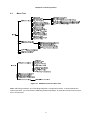
Main Menu ...................................................................................................................................... 48
6.2.1
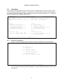
Controller Configuration.......................................................................................................... 48
6.2.1.1.
System .................................................................................................................. 49
6.2.1.2.
Clock Source......................................................................................................... 49
6.2.1.3.
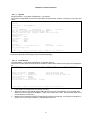
TSI Map ................................................................................................................ 51
6.2.1.4.
Current TSI Map ................................................................................................... 52
6.2.1.5.
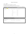
Power/Fan Status ................................................................................................. 53
6.2.1.6.
Link backup function ............................................................................................. 54
6.2.1.7.
QDS1 1:1 protection ............................................................................................. 54
6.2.1.8.
DS0-SNCP Status ................................................................................................ 55
6.2.2
Clock Source Configuration.................................................................................................... 55
6.2.3
Alarm Queue Summary .......................................................................................................... 55
6.2.4
Information Summary ............................................................................................................. 56
6.2.5
Redundant CTRL Information................................................................................................. 56
6.2.6
Performance Report ............................................................................................................... 57
6.2.7
System Setup ......................................................................................................................... 59
6.2.7.1.
System .................................................................................................................. 59
6.2.7.2.
SNMP.................................................................................................................... 62
6.2.7.3.
Password .............................................................................................................. 68
6.2.7.4.
TSI Map Setup ...................................................................................................... 68
6.2.7.5.
Select a New TSI Map .......................................................................................... 69
6.2.7.6.
Copy a TSI Map to another................................................................................... 69
6.2.7.7.
Clear a TSI Map.................................................................................................... 70
6.2.7.8.
Command Line...................................................................................................... 70
6.2.7.9.
Init New Card ........................................................................................................ 71
6.2.7.10.
Clear Empty Slot ................................................................................................... 72
6.2.7.11.
Link back up.......................................................................................................... 73
6.2.7.12.
QDS1 1:1 Protection............................................................................................. 73
6.2.7.13.
DS0-SNCP Setup ................................................................................................. 73
6.2.7.14.
PDH Ring Protection............................................................................................. 74
6.2.7.15.
PDH Ring Diagnostic ............................................................................................ 75
6.2.7.16.
SNTP Setup .......................................................................................................... 75
6.2.7.17.
TELNET/SSH Setup ............................................................................................. 76
6.2.7.18.
Power Setup ......................................................................................................... 77
6.2.7.19.
Multicast Mapping Procedure ............................................................................... 77
6.2.8
System Alarm Setup ............................................................................................................... 83
6.2.9
Firmware Transfer .................................................................................................................. 84
6.2.9.1.
Download Mainboard Firmware............................................................................ 85
6.2.9.2.
Application of upload / download configuration .................................................... 86
6.2.9.3.
Copy Firmware to Redundant............................................................................... 87
6.2.10
Store/ Retrieve Configuration ................................................................................................. 93
6.2.11
Clock Source Setup................................................................................................................ 95
6.2.12
Bit Error Rate Test ................................................................................................................ 101
6.2.13
Alarm Cut Off ........................................................................................................................ 102
6.2.14
Clear Alarm Queue ............................................................................................................... 102
6.2.15
Return to Default .................................................................................................................. 102
6.2.16
Controller Reset.................................................................................................................... 102
6.3
DTE (V.35) Sub-Menu .................................................................................................................. 103
6.3.1
DTE Configuration ................................................................................................................ 103
6.3.2
DTE Status............................................................................................................................ 105
6.3.3
Alarm History ........................................................................................................................ 105
6.3.4
System Setup ....................................................................................................................... 106
6.3.5
Loopback Test....................................................................................................................... 106
6.3.6
Alarm Setup.......................................................................................................................... 107
6.3.7
Upgrade Firmware................................................................................................................ 107
6.3.8
Clear Current Port Performance Data .................................................................................. 108
6.3.9
Return to Default .................................................................................................................. 108
6.3.10
Reset Current DTE Board .................................................................................................... 108
ii
6.4
ATM Frame Relay Sub-Menu....................................................................................................... 109
1-Hour Performance Report ................................................................................................. 109
6.4.1.1.
ATM Frame Relay - T1 ....................................................................................... 109
6.4.1.2.
ATM Frame Relay - E1 ....................................................................................... 111
6.4.2
24-Hour Performance Report ............................................................................................... 112
6.4.2.1.
ATM Frame Relay – T1 ...................................................................................... 112
6.4.2.2.
ATM Frame Relay – E1 ...................................................................................... 113
6.4.3
Port Statistics ........................................................................................................................ 114
6.4.3.1.
T1/E1 Line Availability ........................................................................................ 114
6.4.3.2.
Frame Relay Statistics........................................................................................ 115
6.4.3.3.
ATM Statistics ..................................................................................................... 116
6.4.4
Unit Configuration................................................................................................................. 116
6.4.4.1.
System Setup – ATM/ FR T1.............................................................................. 116
6.4.4.2.
System Setup – ATM/ FR E1.............................................................................. 117
6.4.5
Alarm History ........................................................................................................................ 117
6.4.5.1.
Alarm History - FR to ATM.................................................................................. 117
6.4.5.2.
Alarm History - FR to FR .................................................................................... 118
6.4.6
Port Status ............................................................................................................................ 118
6.4.6.1.
T1/ E1 Status ...................................................................................................... 118
6.4.6.2.
Frame Relay Status ............................................................................................ 119
6.4.6.3.
ATM Status ......................................................................................................... 120
6.4.7
Alarm Queue ........................................................................................................................ 121
6.4.8
Loopback Test....................................................................................................................... 121
6.4.8.1.
ATM Frame Relay – T1 ...................................................................................... 121
6.4.8.2.
ATM Frame Relay – E1 ...................................................................................... 122
6.4.9
Alarm Setup.......................................................................................................................... 122
6.4.9.1.
Alarm Setup - FR to ATM ................................................................................... 122
6.4.9.2.
Alarm Setup - FR to FR ...................................................................................... 123
6.4.10
AM 3440 TSI MAP Setup ..................................................................................................... 123
6.4.10.1.
Map slot D (ATM/FR) to slot B (E1 card)............................................................ 123
6.4.10.2.
Map slot D (ATM/FR) to slot 6 (V.35 card) ......................................................... 124
6.4.10.3.
Map slot D (ATM/FR) to slot 1 (V.35 card) ......................................................... 124
6.4.10.4.
Map slot D (ATM/FR) to HDLC (Inband Channel) .............................................. 125
6.4.11
System Setup ....................................................................................................................... 125
6.4.11.1.
ATM/ FR card Configuration ............................................................................... 125
6.4.11.2.
System Specific to ATM Protocol ....................................................................... 126
6.4.11.3.
Setup Specific to FR-FR Protocol....................................................................... 130
6.4.12
Clear Alarm Queue and History............................................................................................ 133
6.4.13
Clear Performance Data....................................................................................................... 134
6.4.14
Upgrade Firmware................................................................................................................ 134
6.4.15
Unit Load Default Configuration ........................................................................................... 135
6.4.16
Unit Reset............................................................................................................................. 135
6.5
Mini Quad E1 Sub-Menu .............................................................................................................. 136
6.5.1
Unit 1-Hour Performance Report.......................................................................................... 137
6.5.2
Unit 24-Hour Performance Report........................................................................................ 138
6.5.3
Unit Line Availability.............................................................................................................. 139
6.5.4
Unit Configuration................................................................................................................. 139
6.5.5
Unit Status ............................................................................................................................ 140
6.5.6
Unit Alarm History................................................................................................................. 140
6.5.7
Unit Alarm Queue ................................................................................................................. 141
6.5.8
Unit Loopback Setup ............................................................................................................ 141
6.5.9
Unit System Setup................................................................................................................ 142
6.5.10
Unit Clear Performance Data ............................................................................................... 142
6.5.11
Unit Alarm Setup................................................................................................................... 143
6.5.12
Unit Clear Alarm Queue & History........................................................................................ 143
6.5.13
Unit Upgrade Firmware ........................................................................................................ 144
6.5.14
Unit Load Default Configuration ........................................................................................... 144
6.5.15
Unit Reset............................................................................................................................. 145
7 Appendix A – Link Backup Function .......................................................................................................... 146
7.1
Introduction ................................................................................................................................... 146
7.2
Physical Requirement................................................................................................................... 147
6.4.1
iii
7.3
Setup Procedure........................................................................................................................... 147
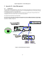
8 Appendix B – Inband Management ........................................................................................................... 149
8.1
Introduction ................................................................................................................................... 149
8.2
Inband Management Setup Procedure ........................................................................................ 150
9 Appendix C –QDS1 1:1 Protection ............................................................................................................ 154
9.1
Introduction ................................................................................................................................... 154
9.2
Setting up Circuit Protection ......................................................................................................... 154
9.2.1
Connecting the Y-Box to the AM 3440 Shelf ........................................................................ 154
9.2.2
Quad E1 card Location......................................................................................................... 156
9.2.3
Setting up a VT-100 Monitor................................................................................................. 156
9.2.4
Step by Step Quad E1 Plug-in card Circuit Protection Setup............................................... 156
9.3
Setting up Line Protection ............................................................................................................ 157
9.3.1
Step by Step Quad E1 Card Line Protection Setup.............................................................. 158
10 Appendix D: Loop AM-3440-A Alarm Trap Information.............................................................................. 161
10.1
Trap definition ............................................................................................................................... 161
10.2
ccAlarmModel: Plug-in card model type...................................................................................... 162
10.3
ccAlarmSlot: Slot index................................................................................................................ 163
10.4
ccAlarmPort: Port index............................................................................................................... 163
10.5
ccAlarmType < 20: Controller alarm............................................................................................ 163
10.6
ccAlarmType: Unit alarm ............................................................................................................. 164
10.7
Alarm Setup Indication ................................................................................................................. 169
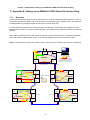
11 Appendix E: Setting up an AM3440-A PDH Shared Protection Ring ........................................................ 170
11.1
Overview....................................................................................................................................... 170
11.2
Setup Instructions ......................................................................................................................... 171
12 Appendix F: Setting up an AM3440-A PDH Shared Protection Ring (T1)................................................. 176
12.1
Overview....................................................................................................................................... 176
12.2
Setup Instructions ......................................................................................................................... 177
13 3E1 DS0-SNCP Setup............................................................................................................................... 182
13.1
Physical Requirement................................................................................................................... 182
13.2
Setup Procedures ......................................................................................................................... 184
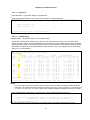
14 Appendix G: AM3440-A Power Consumption............................................................................................ 205
iv
LIST OF FIGURES
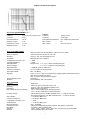
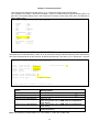
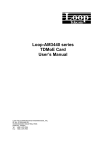
Figure 1-1 Loop-AM 3440 Application Illustration (1 of 2) ................................................................................ 2
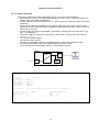
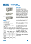
Figure 1-2 Loop-AM 3440 with Y-BOX (2 of 2) ................................................................................................ 2
Figure 2-1 Ground Screw Location................................................................................................................. 16
Figure 2-2 DC Power Without Grounding Application .................................................................................... 17
Figure 2-3 Panel Views - Main Shelf and CPU .............................................................................................. 18
Figure 2-4 Panel Views (for 1/2 slot) - Power Modules .................................................................................. 19
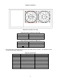
Figure 2-5 Front Panel View - Fan Tray ......................................................................................................... 20
Figure 2-6 Rear Panel View - Fan Tray.......................................................................................................... 20
Figure 2-7 Top View - Fan Tray...................................................................................................................... 21
Figure 2-8 Jumper Location for Mini Quad E1 Interface ................................................................................ 23
Figure 3-1 HDLC using E1 router ................................................................................................................... 41
Figure 6-1 AM3440 Controller: Menu Tree................................................................................................... 47
Figure 8-1 Inband Management Diagram .................................................................................................... 149
Figure 9-1 Connection for AM3440 and Y-BOX with BNC connectors ........................................................ 155
Figure 9-2 Connection for AM3440 and Y-BOX with RJ48C connectors..................................................... 155
Figure 9-3 Line Protection for Quad E1 Card............................................................................................... 157
Figure 13-1 Sample Application for 3E1 DS0-SNCP Setup......................................................................... 183
Figure 13-2 Application for BERT and Loopback Diagnosis ....................................................................... 201
v
LIST OF TABLES
Table 2-1 Power Connector for Fan Tray......................................................................................................... 21
Table 2-2 Power Connector for Main Unit ........................................................................................................ 21
Table 2-3 Console Port..................................................................................................................................... 21
Table 2-4 Ethernet Port .................................................................................................................................... 22
Table 2-5 Alarm Relay Circuit Contact State When Alarm Setup is Enable .................................................... 22
Table 2-6 Alarm Relay Circuit Contact State When Alarm Setup is Disable.................................................... 22
Table 2-7 FUSE Relay Connector .................................................................................................................... 23
Table 2-8 Circuit protection for Mini Quad E1 Interface ................................................................................... 24
Table 2-9 V.35/DB25 DTE Port Pin Definition.................................................................................................. 25
Table 2-10 V.36/ EIA530/ DB25 DTE Port Pin Definition ................................................................................ 26
Table 2-11 X.21/V.11 and DB15 DTE Port Pin Definition ................................................................................ 26
Table 2-12 RS232/DB25 DTE Port Pin Definition ............................................................................................ 27
Table 2-13 DB25 Mini Quad E1 Pin Definition ................................................................................................. 28
Table 2-14 Default Software Configuration ...................................................................................................... 28
Table 3-1 Console Port Setting ........................................................................................................................ 33
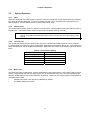
Table 3-2 Alarm Action Table ........................................................................................................................... 34
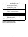
Table 3-3 System Alarm Type Table ................................................................................................................ 35
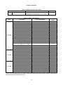
Table 3-4 DTE-PORT Alarm Type Table ......................................................................................................... 36
Table 3-5 Alarm Type Numbers ....................................................................................................................... 36
Table 3-6 Performance Parameter List ............................................................................................................ 37
Table 3-7 Performance Report Options ........................................................................................................... 38
Table 3-8 Front-Panel LED Table (DS1, DTE, ATM/FR) ................................................................................. 39
Table 3-9 Error Message Table........................................................................................................................ 42
Table 6-1 Power consumption.......................................................................................................................... 53
Table 14-1 Power Consumption of AM3440-A Plug-in cards for -48 Vdc (100W) ......................................... 205
Table 14-2 Power Consumption of AM3440-A Plug-in cards for -125 Vdc (100W) Power Module............... 207
vi
D
GB
F
ES
Bitte führen Sie das Gerät am Ende seinerLewbensdauer den zue Verfügung
stehended Rückgabeund Sammelsystemen zu.
At the end of the product's useful life, please dispose of it at appropriate collection
points provided in your country
Une fois le produit en fin devie, veuillez le déposer dans un point de recyclage
approprié.
Para preservar el medio ambiente, al final dela vida útil de su producto, depositelo
en los laguares destinado aello de acuerdo con la legislación vigente.
P
No final de vida útil do producto, por favor coloque no ponto de recolha
apropriado.
I
I Onde tutelare l'ambiente, non buttate l'apparecchio trai i normali rifiuti al termine
della sua vita utile, ma portatelo presso i punti di raccolta specifici per questi rifiuti
previsti dalla normativa vigente.
NL
Wij raden u aan het apparant aan het einde van zijn nuttige levensduur, niet bij
hey gewone huisafval te deponeren, maar op de dearvoor bestemde adressen.
DK
Når produktet er udtjent, bor det børtskaffes via de sæ rlige indsamlingssteder i
landet.
N
Ved slutten av produktets levetid bør det avhendes på en kommunal miljøstasjon
eller leveres til en elektroforhandler.
S
Lämna vänligen in produkten på lämplig återvinningsstation när den är förbrukad.
FIN
Hävitä tuote käytöiän päättyessä viemällä se asianmukaiseen keräyspisteeseen.
PL
Gdy produkt nie nadaje sie juz do dalszego uzytku, nalezy zostawic go w jednym
ze specjalnych punktów zajmujacych sie zbiórka zuzytych producktów w
wybranych miejscach na terenie kraju.
CZ
Po skončení jeho životnosti odložte prosím výrobek na přislušném sbĕrném místé
zřízeném dle předpisů ve vaší zemi.
SK
Po skončení jeho životnosti odovzdajte prosím zariadenie na príslušnom zbernom
mieste podía platných miestnych predpisov a noriem.
SLO
Ko se izdelku izteče življenska doba, ga odnesite na ustrezno zbirno mesto
oziroma ga odvrzite v skladu z veljavnimi predpisi.
GR
Στο Тέλος тης λειτουργικής Ζωής του προϊόντος παρακαλώ
Πετξτε το στα ειōικά σημεία που Παρέχονται οτη χωρα σας.
PRC
當產品使用壽命結束,請在你的國家所提供的適當地點做好回收處理
vii
Chapter 1 Product Description
1 Product Description
1.1
Function Description
For AM3440 Access DCS-MUX:
The Loop-AM3440-A is the Access DCS-MUX that combines various digital access interfaces into E1 or T1
lines for convenient transport and switching. The Loop-AM3440 Access DCS-MUX provides access for a
variety of TDM, IP, and voice interfaces detailed on next page. These interfaces are compatible with other
Loop products. Using these products, a DTE interface can be extended over copper wire pairs or any E1/T1
transport facility. For each Quad E1/T1 plug-in card, each card can have as many as DS0 124/96 time slots
from G.SHDSL, RS232, X.21, V.35, V.36 and EIA530/RS449 interfaces, which can be multiplexed to fill 4
E1/T1 lines. AM3440 also supports fiber optical plug-in card, which can be used to aggregate up to 4 E1
channels onto a single fiber optical interface to connect with other AM3440 or O9310-E1.
AM3440-A has capacity for 12 single slots and 4 mini plug-in slots
This unit is a full cross-connect and can act as a mini DACS. This means that one or more of the WAN ports
can be used as a Drop & Insert function with fractional E1/T1 lines, which can be muxed into a full E1/T1 line.
Redundancy is available in dual CPU controller and power supply options, making it an excellent fit for critical
applications. Although the chassis does not contain and has no need for fan cooling, an external fan tray is
available.
The Loop-AM3440 supports local control and diagnostics by using an external 2-line by 40-character LCD
display and keypads, or by using a VT-100 terminal connected to the console port. The Loop-AM3440 also
supports Ethernet, Telnet, and SNMP, so that it can be controlled and diagnosed from remote locations as well.
An in-band management channel with GUI is available. In addition to the LCD display, there is LED indication
for all plug-in cards.
Finally, the Loop-AM3440 consists of a rugged reinforced aluminum chassis, giving this equipment a more
durable structure and a longer physical life.
For Loop-VV Y-BOX:
Loop-VV Y-BOX is designed to provide 1 for 1 protection function for Quad E1 interfaces of AM3440 shelf.
Two kinds of connector type are available for Y-BOX: BNC connector and RJ48C connectors. Each Y-BOX
with BNC connectors support 1 for 1 protection function for 2 Quad E1 interfaces of AM3440, and each Y-BOX
with RJ48C connectors support 1 for 1 protection function for 8 Quad E1 interfaces of AM3440
1.2
Physical Description
Although it can be used as a desk-top unit, the Loop-AM 3440 is designed for rack mounting. Typically this unit
is to be installed in a Central Office location and is available with choice of single -48Vdc (100W),
-48Vdc(150W), -125Vdc (100W). or -24Vdc (150W), order two for redundancy.
Note: If the user orders -125 Vdc power module, the maximum number of particular cards allowed in slot 1 to
12 is: Four 12-channel FXS, Nine 12-channel Magneto, Eleven 8-channel 2W/4W E&M, Six 8-channel
OCU-DP, Two 4-channel G. SHDSL (1 pair) with line power, Three 2-channel G. SHDSL (2 pairs) with line
power, Two 24-channel FXS.
The front of the unit can accept E1, T1, E1/T1 ATM/Frame Relay, FOM, Router, G.SHDSL, Dry Contact, G.703,
C37.94, TDMoE, Data Bridge, DTE (V.35/V.36, X2.1/V.11, EIA530/RS449, and RS232), Conference, E&M,
Magneto, FXS/FXO and TS interface lines in 4 mini slots and 12 single slots. Also there is a console port for
connection to a VT-100 terminal.
The rear of the unit is blank except for DC fan connectors which will supply power to an external fan tray, if
warranted.
1
Chapter 1 Product Description
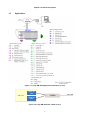
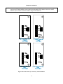
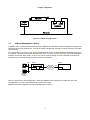
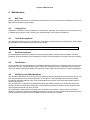
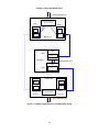
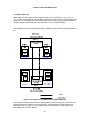
1.3
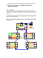
Application
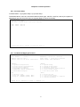
Figure 1-1 Loop-AM 3440 Application Illustration (1 of 2)
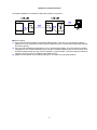
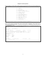
Quad E1
card
Y-BOX
AM 3440
Quad E1
card
Figure 1-2 Loop-AM 3440 with Y-BOX (2 of 2)
2
E1 Line
Chapter 1 Product Description
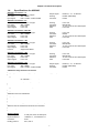
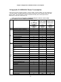
1.4
Specifications for AM3440
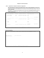
Network Line Interface - T1
Line Rate
1.544 Mbps ± 32ppm
Line Code
AMI or B8ZS
Input Signal
DSX-1 0 dB to -30 dB w/ALBO
Output Signal
Framing
Connector
DSX1w/0, -7.5, -15 dB LBO
D4/ESF (selectable)
RJ48C
Network Line Interface - E1
Line Rate
2.048 Mbps ± 50 ppm
Line Code
AMI or HDB3
Input Signal
ITU G.703
Output Signal
ITU G.703
Framing
Connector
Electrical
Jitter
ITU G.704
BNC/RJ48C
75 ohm Coax/120 ohm twisted pair
ITU G.823
Network Line Interface - Mini 4E1
Line Rate
2.048 Mbps ± 50 ppm
Line Code
AMI or HDB3
Input Signal
ITU G.703
Output Signal
ITU G.703
Framing
Connector
Electrical
Jitter
ITU G.704
DB25S
75 ohm Coax/120 ohm twisted pair
ITU G.823
Network Line Interface - 3E1
Line Rate
2.048 Mbps ± 50 ppm
Line Code
AMI or HDB3
Input Signal
ITU G.703
Output Signal
ITU G.703
Function
Support DS0-SNCP
Framing
Connector
Electrical
Jitter
ITU G.704
BNC/RJ48C
75 ohm Coax/120 ohm twisted pair
ITU G.823
Network Line Interface - 4E1
Line Rate
2.048 Mbps ± 50 ppm
Line Code
AMI or HDB3
Input Signal
ITU G.703
Output Signal
ITU G.703
Framing
Connector
Electrical
Jitter
ITU G.704
BNC/RJ48C
75 ohm Coax/120 ohm twisted pair
ITU G.823
Network Line Interface - 4T1
Line Rate
1.544 Mbps ± 32 ppm
Line Code
AMI or B8ZS
Input Signal
DSX-1 0 dB to -30 dB w/ALBO
Output Signal
Framing
Connector
DSX1w/0, -7.5, -15 dB LBO
D4/ESF (selectable)
RJ48C
ATM Frame Relay Network Line Interface
Supporting Network Interworking (FRF.5) and service interworking (FRF.8).
Network Interface:
T1 ATM UNI
− T1 Module:
FR (n x 64 Kbps, n=1 to 24)
E1 ATM UNI
− E1 Module:
FR (n x 64 Kbps, n= 1 to 31)
Up to 31 logical FR channels can be concentrated/ de-concentrated to FR or ATM.
Service Ports:
n x 64 Kbps, n=1 to 24
− T1/FT1 interface:
n x 64 Kbps, n= 1 to 31
− E1/FE1 interface:
Support HDLC to FR
Support HDLC to ATM
Supporting FR to FR multiplexing.
Support up to 128 DLCIs for total of 31 FR interfaces.
Support up to 128 VCs.
Peak cell rate on DLCI basis.
Manufacturing disable/enable ATM scrambling for internal testing (E1 ATM only).
AAL0 and AAL5 are supported in the ATM adaptation layer.
Support VBR service.
ANSI and ITU FR management protocols are supported.
Flash memory software download through RS485.
Only the PVC type of ATM/FR service is supported.
Router Interface
Number of ports
Physical Interface
Connector
Routing protocol
2 LAN ports, Max. 32 WAN ports
10 BaseT x 1, 10/100 BaseT x 1
RJ45
RIP-I, RIP-II
3
Chapter 1 Product Description
Data Rates
Supporting Protocols
Router-A Interface
Number of ports
Physical Interface
Connector
Routing protocol
Supporting Protocols
Diagnostic
QoS
Router-B Interface
Number of ports
Physical Interface
Connector
Routing protocol
Supporting Protocols
Diagnostic
QoS
Channelized N x 64 Kbps, 1≤ n ≤32
TCP/IP, PPP, HDLC
2 LAN ports, Max. 64 WAN ports, Each WAN port has data rate n x 64K bps, 1≤ n ≤32 (≤ 4Mbps for total
of all 64 WAN ports
10/100 BaseT x 2
RJ45
RIP-I, RIP-II, OSPF, Static
PPP (IPCP/BCP), MLPPP, HDLC, Frame Relay, and Cisco compatible HDLC, NAT/NAPT, DHCP
Ping, Trace route
Rate limit
8 LAN ports, Max. 64 WAN ports. Each WAN port has data rate n x 64K bps, 1≤ n ≤32 (≤ 8Mbps for total
of all 64 WAN ports
10/100 BaseT x 8
RJ45
RIP-I, RIP-II, OSPF, Static
PPP (IPCP/BCP), MLPPP, HDLC, Frame Relay, and Cisco compatible HDLC, NAT/NAPT, DHCP
Ping, Trace route
Rate limit
Terminal Server Interface
Connecotr
Ports
Data Rate
Layer 2 Protocol of RS232 Async
Layer 2 Protocol of RS232 Sync
Terminal Server Function
Router Function
One DB-44 converseion cable to one DB-9 and two DB-25 connecotrs
One Async RS232 port, two Async/Sync RS232 ports.
The two Async/Sync ports can be configured independently as Asynchronous or
Synchronous.
Async: 1.2kbps, 2.4kbps, 4.8kbps, 9.6kbps, 19.2kbps, 38.4kbps
Sync: 64 kbps
Raw data, SLIP
PPP
Supports Telnet
RIP- I, RIP-II, Static Route
Fiber Optical Interface / 1FOM-A Interface
Source
MLM Laser
Line Code
Scrambled NRZ
Wavelength
1310 ± 50 nm, 1550 ± 40 nm
Detector Type
PIN-FET
Protection
Optional 1+1 APS
50 Km reach
NOTE: Longer or shorter, 15 to 120Km, on special order.
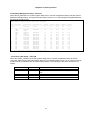
Optical Fiber Interface Characteristics
Optical Module
Single
Single
Fiber Direction
Dual uni-direction
Wavelength (nm)
Connector
Distance (km)
1310
SC (Subscriber Connector)
30
1310
SC (Subscriber Connector)
50
1310
FC (Fiber Connector)
30
1550
SC (Subscriber Connector)
20
1550
SC (Subscriber Connector)
100
Single bi-direction (master)
1310/1550
SC (Subscriber Connector)
30
Single bi-direction (slave)
1310/1550
SC (Subscriber Connector)
30
4
Chapter 1 Product Description
G.SHDSL Line Interface
Number of ports
Line Rate for 4-channel G.shdsl
Line Rate for 2-channel G.shdsl
Line Code
Connecotr
Electrical
Sealing current
Clock Source
Diagnostic Test
2 or 4
n x 64 Kbps (n=3 to 31)
n x 64Kbps (n= 3 to 15)
16- TCPAM, full duplex with adaptive echo cancellation
RJ45
Unconditioned 19-26 AWG twisted pair
Max. 20 MA source current
From System, Line
G.SHDSL Loopback: To-LINE, To-bus,
BERT:QRSS
DTE Interface (X.21)
Data Port
6-port DTE X.21 card; 1-port DTE X.21 card
Data Rate
56 or 64 Kbps, n = 1 to 32
Connector
DB15S
DTE Interface (V.35)
Data Port
6-port DTE V.35 card; ; 1-port V.35 card
Data Rate
56 or 64 Kbps, n = 1 to 32
Connector
DB25S (optional conversion cable DB25S to M34 connector)
DTE Interface (V.36)
Data Port
6-port DTE V.36 card
Data Rate
56 or 64 Kbps, n = 1 to 32
Connector
DB25S (optional conversion cable DB25S to DB37 connector)
DTE Interface (EIA530/RS449)
Data Port
6-port EIA530 DTE card; 1-port EIA530 card
Data Rate
56 or 64 Kbps, n = 1 to 32
Connector
DB25S (optional conversion cable DB25S male to DB37 female connector for RS449)
DTE Interface (RS232)
Data Port
1-port RS232 card
Data Rate
56 or 64 Kbps *n, n=1 - 2
Mapping
Any sequential time slots
DTE Interface (RS232-X.50 mux. 8-port)
Data Port
8-port RS232 cards
MUX
Maximum 5 subrate port per 64K bps
Data Rate
Mux mode
Asynchronous
Independent mode
Mux mode
Synchronous
Independent mode
0.6K, 1.2K, 2.4K, 4.8K, 9.6K
0.6K, 1.2K, 2.4K, 4.8K, 9.6K, 19.2K, 38.4K
0.6K, 1.2K, 2.4K, 4.8K, 9.6K
0.6K, 1.2K, 2.4K, 4.8K, 9.6K, 19.2K, 38.4K, 48K, 64K
Port Number
Card Type
Eight RJ48
Two DB44 + Two RJ48
Connector
1
2
3
4
5
6
7
8
Async Note 1
Async Note 1
Async
Async Note 1
Async Note 1
Async
Async
Async
Async/Sync Async/Sync Async
Async
Async
Async/Sync Async/Sync Async
Eight RJ48 (port 1 to port 8)
DB44 (port1,port2,port3), DB44 (port4,port5,port6), RJ48 (port7) and RJ48(port8)
Conversion Cable
Electrical
A three-into-one conversion cable adapts the DB44 connector to 3 connecters (one DB9S and two
DB25S)
RS232 Interface, DCE
Note 1: Up to 19.2 Kbps achieved by oversampling at 64 Kbps
DTE Interface (Data Bridge Card)
Data Port
8-port data bridge card (each card supports up to 120 DS0 for data bridge)
Feature
20 end points per multi-drop circuit to into a logical ended 56K or 64K channel
Per port supports bridge function to N remote Trib. Site (N=1~20)
5
Chapter 1 Product Description
Data Rate
Bridge function
Asynchronous
Support to receive 1200 to 19200 bps asynchronous data via oversampling channel
one port with one DS-0 to many (Maximum is 20 for remote Tributary data box )
20 drops for each DS0 to remote Tributary data box and 8 ports RS232 shared the 128 channels.
OCUDP Interface Card
Ports
Line Status Indicator
Network Connector
Electrical Network Connection
Transmit Source Impedance
Receive Input Imdednace
Receiver Sensitivity
Dynamic Range
Pulse Amplitude
Sealing Current
Operating Modes
Circuit Rates
Encoding and decoding rules
Maintenance control
Fault and Performance
Enviroment
Specification Standard
8 Ports for each card
Per Port 1 dual color LED; Red for LOS, Green for SYNC
RJ48S
Tip/Ring and Tip1/Ring1
135 Ohms +/-20%
135 Ohms +/-20%
0 to 43 dB loop loss at 72K & 56K
0 to 34 all other rates Automatic line equalization
+/- 1.5V (+/-10%) peak, all rates except 9.6K
+/-0.75 (+/-10%) peak at 9.6K
Bipolar Return to zero, 50 duty cycle
Typically 16mA DC
4-wire DDS
Switched 56 support is optional
SYNC: 2.4, 4.8, 9.6, 19.2, 56, 72 kbps (64k) clear channel
Conforms with AT&T Pub 41458
Use bipolar violation to indicate control information: Idle, out of service, Zero
Subsitution using unframed loops
DSU Non-latching loop-back code (for 2.4, 4.8, 9.6, 19.2, 56k circuit rate)
DSU Latching loop-back (TIP, LSC, LBE, FEV) code (for 72k circuit rate)
Machine maintenance OCU/DP card operation:
Payload loopback
OCU loopback
Local loopback
Bi-directional loopback
V.54 remote loopback code
Custom defined remote loopback code
BERT test support all ones, all zeros, 2047,511,63 pattern.
LOS, OOS, ES, SES and UAS alarm.
Current, last 96 registry and 7 days performance storage.
Operating: 0-50°C
Storage: -25-75°C
Humidity: Up to 90% RH non-condensing
ANSI T1.410; AT&T Pub 62319, AT&T Pub 62310, ITU-T V.54
Co-directional Interface
Interface
ITU G.703 64 Kbps co-directional interface
Connector
120ohm, RJ48
Line Distance
Up to 500 meters
Loopack
DTE Payload Loopback, Local Loopback
C37.94 Interface
Source
Wavelength
Conncetor
Optical Budget
Dry Contact Interface
Inputs 8-channel
Connector
Internal Resistance
Activation Current
Deactivation Current
Allowable Current
LED
820 nm 2Km reach
ST
50 Mircon core/9.6 db
62.5 Mircon core/15db
2-port per card, 4-pair per port
RJ45
1K
3 ma
1.5 ma
4 ma
Outputs 8-channel
Connector
Initial Insulation Resistance
Max. Current
Max. Voltage
6
8-pair per card
Screw type
Min. 100M ohm (at 500 Vdc)
5A
100 Vdc, 250 Vac
Chapter 1 Product Description
Dry Contact Type B Interface
Inputs 8-channel
2-port per card, 4-pair per port
Connector
RJ45
Internal Resistance
100 K
Activation Current
3 ma
Deactivation Current
1.5 ma
Allowable Current
4 ma
Voice Card (Q2EM, Q4EM)
Connector
Alarm Conditioning
Encoding
Outputs 8-channel
Connector
Initial Insulation Resistance
Max. Current
Max. Voltage
8-pair per card
Screw type
Min. 1000M ohm (at 500 Vdc)
2A
220 Vdc, 250 Vac
DB44 connector with external DB44 to 4 RJ45 connector cable
CGA busy after 2.5 seconds of LOS, LOF
Impedance
Longitudinal Conversion Loss
Longitudinal Balance
Gain Adjustment
(all port settings)
Signal/Distortion
Frequency Response
Idle Channel Noise
Signaling
A-law or μ-law, user selectable per card
Balanced 600 ohm or 900ohm
> 46dB
> 63dB
Normal mode 0, -3, -6 or +7 dB for transmit (D/A) gain
0, -3, -6 or +10 dB for receive (A/D) gain
> 25dB with 1004 Hz, 0dBm input
+0.5 to -0.9db from 300 to 3400 Hz
Max. –65 dBm0p
Type I, II, III, IV, V and TO (Transmit Only) signaling options (manufacture option)
In-band signaling tones
Modems
Side: A or B (manufacture option)
Wire: 2 wire or 4 wire (manufacture option)
transparent
Full compatibility with V.90 modems
Voice Card (8EM)
Connector
Alarm Conditioning
Encoding
Impedance
Gain Adjustment (Per-port setting)
I/O Power Range
Gain Variation
Frequency Response
Longitudinal Conversion Loss
Total Distortion
Idle Channel Noise
Carrier Connection
Wire Mode
Signaling
Modems
Eight RJ45
CGA busy after 2.5 seconds of LOS, LOF
A-law or μ-law, user selectable together for all
Balanced 600 or 900 ohms
-16 to +7 dB / 0.1dB step for transmit (D/A) gain
-16 to +14 dB / 0.1dB step for receive (A/D) gain
A/D Analog input level: -66 dBm (0.00039 Vrms) ~ + 3 dBm (1.09 Vrms)
D/A Analog output level: -66 dBm (0.00039 Vrms) ~ + 4 dBm (1.22 Vrms)
± 0.5 dB at 0 dBm0 input
± 0.5 dB at 0 dBm0 input
> 46dB
> 35 dB at 0 dBm0 input
Max. –65 dBm0p
Side A ( exchange side) and Side B (carrier side) setup by side switch
2 wire and 4 wire (programmable)
Type 1, Type 2, Type 3, Type 4, and Type 5, Transmit only (programmable)
Full compatibility with V.90 modems
7
Chapter 1 Product Description
All in-band signaling tones are carried transparently by the digitizing process.
Customer is responsible for in-band signaling compatibility between a telephone and a switch, or between a PBX and a switch.
Voice Card 12 MAG (Magneto)
Connector
Alarm Conditioning
Encoding
Impedance
Longitudinal Conversion Loss
Gain Adjustment
Signal/ Distortion
Frequency Response
Idle Channel Noise
Min Detectable Ringing Voltage
Ringing Detectable Across
Ringing Generation
Twelve RJ11
CGA busy after 2.5 seconds of LOS, LOF
A-law or μ-law, user selectable together for all
Balanced 600 or magneto telephone impedance match
> 46dB
-21 to +10 dB / 0.1dB step transmit & receive
> 25dB with 1004 Hz, 0dBm input
- 0.25 to -1 dB from 300 to 3400 Hz, coincide with ITU-T G.712
Max. –65 dBm0p
16 Vrms
L1 and L2 (Tip and Ring), L1 and GND (Tip and GND)
Voltage: 76 Vrms (sine wave)
Frequency: 20Hz (with optional choices of 16, 25, 50 Hz)
Cadence:
1. Normal:
Ring after crank
2. PLAR ON:
-Single Ring Type: ring for 2 sec. and stop, or ring for 4 sec. and stop
-Continuous Ring Type: 1 sec on 2 sec off, or 2 sec on 4 sec off
Ringing Send Across
L1 and L2 (Tip and Ring), L1 and GND (Tip and GND)
Signaling
Magneto MRD(Ringing across Tip and Ring or Tip and Ground)
Signaling Bit A,B,C,D
Programable
Signaling is carried transparently by the digitizing process.
Use Magneto card default setting for communications between magneto telephones
Use Magneto card PLAR mode setting for communications between a magneto telephone and a regular telephone
8
Chapter 1 Product Description
Conference Card
RS232 Interface
Data Port
ASYNC Data Rate
SYNC
Connector
FXS Voice Interface
Connector
Encoding
Longitudinal Conversion Loss
Cross Talk Measure
Gain Adjustment
Signal/ Distortion
Idle Channel Noise
Loop Resistance
FXS Loop Feed
FXS Ringing
Signaling
E&M Voice Interface
Connector
Encoding
Impedance
Longitudinal Conversion Loss
Gain Adjustment
Signal/Distortion
Idle Channel Noise
Carrier Connection
Phone line power+12V
Operation mode
Wire Mode
Signaling Type
EM Ringing
2-ports per card
300, 600, 1.2K, 2.4K, 4.8K, 9.6K, 19.2K
not supported
Two DB9, DCE, female
Two RJ11
G.723
> 46dB
Max -70dBm0
transmit (D/A) gain 0, +6dB
receive (A/D) gain +6, 0, -6dB
> 25dB with 1004 Hz, 0dBm input
Max. –65 dBm0p
Max 1800 ohm
Normal -48 Vdc with 25mA current limit
2 REN
20Hz
76 Vrms
2 sec on / 4 sec off for 1 min, or 1 sec on / 2 sec off for 30 sec (programmable)
Loop Start, DTMF
Two RJ45
G.723
Balanced 600 ohms
> 46dB
transmit (D/A) gain 0, +6dB
receive (A/D) gain +6, 0, -6dB
> 25dB with 1004 Hz, 0dBm input
Max. –65 dBm0p
Side A = exchange side, Side B = carrier side (Jumper selectable)
Type P (Jumper enable)
Master, standard (Jumper selectable)
4 wire
Type 1, Type 4, and Type 5 (Jumper selectable)
Single rainging for 5 sec only
2 sec on / 4 sec off for 1 min, or 1 sec on / 2 sec off for 30 sec (programmable)
9
Chapter 1 Product Description
Voice Card (QFXS, QFXO)
Connector
Alarm Conditioning
Encoding
AC impedance
Longitudinal Conversion
Loss
Loss Adjustment
Signal/Distorition
Frequency Response
FXS Loop Feed
FXS Ringing
FXO Ringing REN
Metering Pulse
Signaling
Inband Singaling Tone
Four RJ11
CGA busy after 2.5 seconds of LOS, LOF
A-law or μ-law, user selectable per card
Balanced 600 or 900 ohms, user selectable per card
> 46dB
0,3,6, or 9 dB transmit & receive, user selectable per card
> 25dB with 1004 Hz, 0dBm input
-0.25 to -1 dB from 300 to 3400 Hz
Nominal -48 Vdc with 25mA current limit per port
1 REN at 5000 meters per port
20 Hz, other frequencies (manufacture option): 16.7 Hz, 25 Hz, 50 Hz
76 Vrms (sine wave)
User selectable ring cadence per card for PLAR function: 2 sec on 4 sec off, or 1 sec on 2 sec off
Ringing REN
0.5B (AC)
Detectable Ringing
25 Vrms
Loop Resistance
≤ 1800 Ω
DC impedance (ON-HOOK)
> 1M Ω
DC impedance (OFF-HOOK)
235 Ω @ 25mA feed
90 Ω @ 100mA feed
12 KHz/16 KHz
Power: 10dBm
Sensitivity: -18dBm to -45dBm (manufacture option)
Loop Start, GND-Start, Metering Pulse (12 KHz, 16 KHz), DTMF, Dialing Pulse, PLAR,
Battery Reverse (support Line Reverse Signaling for Billing)
transparent
Voice Card (12FXS,12FXO,24FXS,24FXO)
12 FXS/FXO Connector
Twelve RJ11
24 FXS/FXO Connector
One RJ21X Female
Alarm Conditioning
CGA busy after 2.5 seconds of LOS, LOF
Encoding
A-law or μ-law, user selectable together for all
AC Impedance
Balanced 600 or 900 ohms (selectable together for all)
Longitudinal Conversion Loss
> 46dB
Cross talk measure
Max -70dBm0
Gain Adjustment
-21 to +10 dB / 0.1dB step transmit & receive
Signal/ Distortion
> 25dB with 1004 Hz, 0dBm input
Frequency Response
- 0.25 to -1 dB from 300 to 3400 Hz, coincide with ITU-T G.712
Idle Channel Noise
Max. –65 dBm0p
Variation of Gain
±0.5dB
FXO
Ringing REN
0.5B (AC)
Detectable Ringing
25 Vrms
Loop Resistance
≤ 1800 Ω
DC Impedance (ON-HOOK)
> 1M Ω
DC Impedance (OFF-HOOK)
235 Ω @ 25mA feed
90 Ω @ 100mA feed
FXS Loop Feed
-48Vdc or -24Vdc with 25mA current limit per port
Jumper Selectable: 25mA, 30mA, 35mA
FXS signalling
Normal / Automatic Ring down
FXS Ringing
1 REN at 5K meters per port
16.7Hz, 20Hz, 25Hz, 50Hz, user selectable for all ports
38 to 85 Vrms (sine wave), 76 Vrms for default Ring Voltage
2 sec on 4 sec off, or 1 sec on 2 sec off optional for PLAR
Signaling
Loop Start, DTMF, pulse, PLAR, Battery Reverse
Optional Signaling (for special
Ground Start, Metering pulse (12 KHz, 16 KHz), and P( in PLAR mode, PLAR signalling bits
order)
are programmable.
Signaling Bit A,B,C,D
Programable bit
All in-band signaling tones are carried transparently by the digitizing process.
Customer is responsible for in-band signaling compatibility between a telephone and a switch, or between a PBX and a switch.
-24Vdc power is for FXS PCB version L and up
10
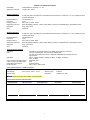
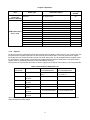
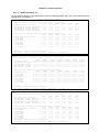
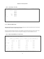
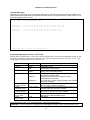
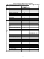
Chapter 1 Product Description
Phone Line Monitor Card
Connector
Alarm Conditioning
Encoding
Impedance
Total Distortion
Frequency Response
Four RJ11 connectors
CGA busy after 2.5 seconds of LOS, LOF
A-law or μ-law, user selectable as a group
Balanced 15K Ohm
> 35dB with 1004 Hz, 0dBm input
0 ~ -0.5 dB from 300 to 2000 Hz
-0.5 dB ~ -2 dB from 2000 to 3300 Hz
Idle Channel Noise
> -60 dBm0
Gain Adjustment
0, -3, -6 or +7 dB for PLM (B) transmit gain (D/A)
(All Port Setting)
0, -3, -6 or +3dB for PLM (A) receive gain (A/D)
Off-Hook Detect Level
< -6V Line to GND
Operational Temp.
0°C to 50°C
Relative Humidity
0% to 95%
Power
110 ~ 220 VAC, -48 Vdc
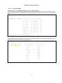
All in-band signaling tones are carried transparently by the digitizing process.
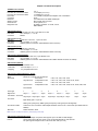
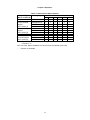
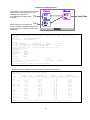
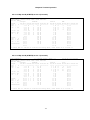
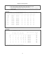
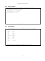
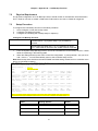
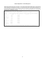
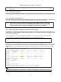
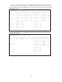
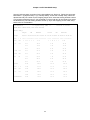
Signaling Bits
Normal
AB Bit Invert
Tx
Status
PLM (A) to Line
Rx
A
B
C
D
Line On Hook
1
1
0
Line Off Hook
0
1
0
A
B
Tx
C
D
Rx
A
B
C
D
1
0
1
0
1
1
1
1
0
1
A
B
C
D
Battery (-48V)
1
1
0
1
0
1
0
1
Battery (-6V)
0
1
0
1
1
1
0
1
PLM (B) to Monitor
11
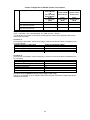
Chapter 1 Product Description
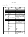
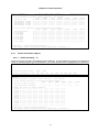
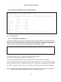
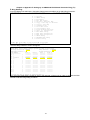
TDMoE
Combo Gigabit Ethernet(GbE) Interface
Number of Ports
2
Speed
10/100/1000M bps
Connector
RJ45 for twisted pair GbE, LC for optical GbE, auto detection
Gigabit Ethernet(GbE) Interface
Number of Port
2
Speed
10/100/1000 BaseT
Connector
RJ45
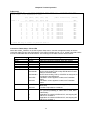
Ethernet Function
Basic Features
MDI/MDIX for 10/100/1000M BaseT auto-sensing
Ping function contained ARP
Per port, programmable MAC hardware address learn limiting (max. MAC table 8192 (8k) entry)
Packet Delay Variation:
- Unframed T1: Up to 340 ms
- Framed T1: Up to 256 ms
- E1:up to 256 ms
- Framed T1 with CAS: Up to 192 ms
Packet Transparency
Packet transparency support for all types of packet types including IEEE 802.1q VLAN and 802.1ad
(Q-in-Q)
QoS
User configurable 802.1p CoS, ToS in out going IP frame
Traffic Control
Ingress packet Rate limiting buckets per port for Ethernet port
Supporting Rate-based and Priority-based rate limiting for LAN port
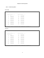
Granularity:
a. From 64 Kbps to 1 Mbps in increments of 64 Kbps
b. From 1 Mbps to 100 Mbps in increments of 1 Mbps
c. From 100 Mbps to 1000 Mbps in increments of 10Mbps
Pause frame issued when the traffic exceeding the limited rate before packet dropped following
IEEE802.3X
Jitter & Wander
PPM: per G.823 Traffic
PPB: per G.823 Synchronous*
Standard Compliance
IETF
TDMoIP (RFC5087), SAToP (RFC4553), CESoPSN (RFC5086)
IEEE
802.1q, 802.1p, 802.1d, 802.3, 802.3u, 802.3x, 802.3z, 802.1s, 802.1w
12
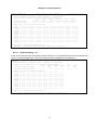
Chapter 1 Product Description
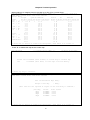
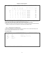
Clock Source
Internal, Line Interface, External (E1/T1/2048 KHz)
Alarm Relay
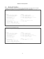
Alarm Relay: max. current: 1A for 24VDC/ 0.625A for 48VDC
Fuse alarm, and performance alarm
System Configuration Parameters
Active Configuration, Stored Configuration, and Default Configuration (Stored in Non-volatile Memory)
Management
Console
Ethernet
Inband Management
Ethernet LCD
Performance Monitor
Performance Registers
Separate Registers
Performance Reports
Alarm Queue
Threshold
Electrical: RS232; Connector: DB9, female
User Interface: Menu driven VT-100
1 port, Connector: RJ45
10/100 Base T, SNMPv1, v3/Telnet/SSH
Inband 64 Kbps, support HDLC/PPP
Optional
Last 24 hours performance in 15 minute intervals and last 7 days in 24 hour summaries
Network, user, and remote site
Reports include E1 Bursty Errored Second, Severe Errored Second, Degraded Minutes. Also
available in Statistics (%)
Containing 300 alarm records which record the latest alarm type, location, and date & time
Bursty Seconds, Severely Errored Second, Degraded Minutes
Diagnostics
Loopback
Test Pattern
E1/T1 interface (Line Loopback, Payload Loopback, Local Loopback)
For Controller: 220-1, 215-1, 211-1, 29-1, and 4-bye user define pattern
Physical /Electrical
Dimensions
432.4 x 220 x 223.5 mm (W×H×D)
Power
Single/ Dual -48 Vdc: -36 to -75 Vdc, 100 Watts max.
Single/ Dual -48 Vdc: -36 to -75 Vdc, 150 Watts max.
Single/ Dual -24 Vdc: -18 to -36 Vdc, 150 Watts max
Single/ Dual -125 Vdc: -40 to -150 Vdc, 100 Watts max
Temperature 0-55°C
Humidity
0-95%RH (non-condensing)
Mounting
Desk-top stackable, 19” /23” rack mountable
Line Power
Available only with DC power for G.SHDSL card only
Supply
Power
Max 110 Watts
Consumption
Certification
EN55022 Class A, EN50024, FCC Part 15 Class A, FCC Part 68, CS-03, IEC60950, UL60950
Compliance
ITU G.703, G.704, G.706, G.732, G.736, G.823, G.826, G.711, G.775, O.151, V.11, V.28, V.54
IETF SNMP v.3 (RFC2571~2575)
13
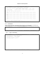
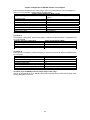
Chapter 1 Product Description
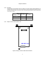
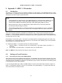
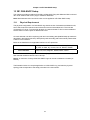
Specifications for Loop-VV Y-BOX
LINE
Connector
Port Number
BNC or RJ48C
For Y-BOX with BNC connectors: 4 line ports
For Y-BOX with RJ48C connectors: 16 line ports
For Y-BOX with BNC connectors: support 2 Quad E1 plug-in card, 4 active E1, 4 standby E1
For Y-BOX with RJ48C connectors: support 8 Quad E1 plug-in cards, 16 active E1, 16 standby E1
For Y-BOX with RJ48C connectors: support 8 Quad T1 plug-in cards, 16 active T1, 16 standby T1
Protection
Mechanical
Height
Width
Depth
44.5 mm/ 1.75 in
432 mm/ 17 in
100 mm/ 3.9 in
* Future Option
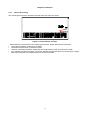
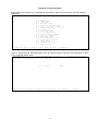
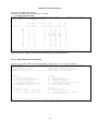
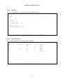
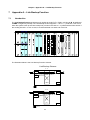
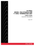
Front Panel View (with BNC connectors)
Loop-VV
TM
Y-BOX
1
A-TX
LINE-TX
B-TX
A-RX
LINE-RX
B-RX
1
2
A-TX
LINE-TX
B-TX
A-RX
LINE-RX
B-RX
2
3
A-TX
LINE-TX
B-TX
A-RX
LINE-RX
B-RX
3
4
A-TX
LINE-TX
B-TX
A-RX
LINE-RX
B-RX
4
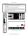
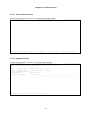
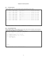
Front Panel View (with RJ48C connectors)
Loop-VV
A
LINE 9
B
A
LINE 10
B
A
LINE 11
B
A
LINE 12
B
A
LINE 13
B
A
LINE 14
B
A
LINE 15
B
A
LINE 16
B
A
LINE 1
B
A
LINE 2
B
A
LINE 3
B
A
LINE 4
B
A
LINE 5
B
A
LINE 6
B
A
LINE 7
B
A
LINE 8
B
TM
Y-BOX
14
Chapter 2 Installation
2 Installation
CAUTION:
• Only qualified service personnel shall install and maintain the system.
• This equipment must be connected to an earth socket-outlet, which has a permanent
connection to protective earth with a cross-sectional area of not less than 2.5 mm2.
• Ensure protective earthing connected before install /uninstall telephone wires.
• Never install telephone wiring during a lightning storm.
• Never install telephone jacks in wet locations unless the jack is specifically designed for wet
locations.
• Never touch uninsulated telephone wires or terminals unless the telephone line has been
disconnected at the network interface.
• Use caution when installing or modifying telephone lines.
2.1
Site Selection
The following list indicates a site selection guideline. User need to follow this guideline to select a proper
installation site.
• Location of the Rack should be part of the central office equipment layout design. Considerations should be
given to entrance cable routing and -48 Vdc (100W), -48 Vdc (150W), -125 Vdc (100W) or -24 Vdc (150W)
power.
• The installation site should have -48 Vdc power. An optional AC/DC power converter can be used. Use
only with Class 2 power source, -48 Vdc, 100 watts.
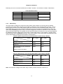
2.2
Mechanical Installation
AM3440 can be installed as a desk top unit or mounted on a 19 inch or a 23 inch rack. Mounting of the unit in a
rack follows standard telephone rack mount practices. Accessories to install on a 19 inch or 23 inch rack is
provided. As a desk-top unit AM3440 is stackable.
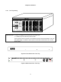
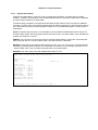
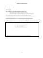
2.3
Electrical Installation
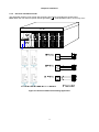
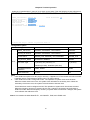
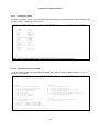
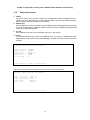
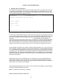
Central office -48 Vdc power is wired to terminal blocks in the front of the AM3440, shown in Figure 2-1.
Central office alarm system is wired to the Alarm Relay terminal blocks. For connection to the CONSOLE
(button down/ button up) connector for maintenance and administration, a CONSOLE port with DB9 connector
is located on the front panel, see also Figure 2-1. The RJ45 connector is for an Ethernet connection. For direct
modem or VT-100 terminal connection, use a null modem cable to connect the CONSOLE port on the front
panel.
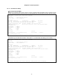
NOTE: When AM3440 is plugged with two CPU cards, both of these two CPU cards can be primary (master)
or redundant (slave) which only depends on which CPU card completes boot up first after powering
on the main unit. User can tell which CPU card is primary or redundant from the status of CPU card's
ACTIVE led. If ACTIVE led is flashing green, the CPU card is primary. When one CPU fails, the other
becomes master and remains master even when the failed is replaced.
15
Chapter 2 Installation
2.3.1 Chassis Grounding
The chassis ground screw is located in the right hand side of the rear panel.
Grounding
Screw
Figure 2-1 Ground Screw Location
When attaching a ground wire to the chassis ground screw, please follow these instructions.
Use copper grounding conductors of 18 AWG
Conductors should not be of dissimilar metals.
The bare conductors should be coated with anti-oxidant before crimp connections are made.
Any unplated connection surfaces, connectors, braided strap and bus bars must be bought to a bright
finish and coated with anti-oxidant before connections are made.
16
Chapter 2 Installation
2.3.2 Electrical Installation Guide
The application drawing of DC power with grounding and without grounding are shown below.
Note: When the user uses DC power without grounding ( ), noise problems and E1 errors may occur.
Figure 2-2 DC Power Without Grounding Application
17
Chapter 2 Installation
For Dual-CTRL protection:
NOTE: When an AM3440 has two controller plug-in cards, on applying power, the left controller (CTRL1) will
always be the primary, and the right controller (CTRL 2) will always be the redundant. If the
redundant card’s configuration is different from the primary, the redundant CTRL will synchronize its
configuration from the primary CTRL after the boot up and initiation process.
This synchronized takes 1-2 minutes. During configuration synchronization, the LED will show the
following sequence
1. LED for primary CTRL: <power> green, <active> flashing green.
2. LED for redundant CTRL: <power> flashing green, <active> dark.
Redundant CTRL will send heart beat every 0.5 second. After 5 consecutive no response from
primary CTRL, meaning primary CTRL dead, redundant CTRL will take over AM3440 and become
primary. Primary warm restart (reset) will not switch control back to the left CTRL, while Primary cold
restart will switch. Switching time is less than 50ms.
Condition: To avoid sync failure, the brand and the firmware version of CTRL1 and CTRL2 should
be the same.
PO
W
ER
AC
TI
VE
AL
AR
M
POWER
A
B
C
E1/T1(C)
E1/T1(D)
CPU-1
CPU-2
C
P
U
C
P
U
1
2
1
2
3
4
5
6
7
8
9
E1/T1 E1/T1
D
SYNC/TES
T
E1/T1(A)
E1/T1(B)
LOF
BPV
E1/T1 E1/T1
RAI/AIS
ACO
TIP
RING
NC
COM
EXT.
CLOCK
FUSE
RELAY
Main Access DCS-Mux Shelf - Front Side
NO
NC
COM
ALARM
RELAY
NO
ETHERNET
CONSOLE
9600,N,8,1
Grounding
Screw
LCD INTERFACE
Main Access DCS-Mux Shelf - Rear Side
CPU
Figure 2-3 Panel Views - Main Shelf and CPU
18
10
11
12
Chapter 2 Installation
OTE:
When these plug-in cards( two CPU cards, four mini Quad E1 plug-in cards, ten G.shdsl plug-in
cards, and one 100W UM5813 power module) are plugged into an AM3440, one more 100W
UM5813 power module should be added to plug into the AM3440.
Figure 2-4 Panel Views (for 1/2 slot) - Power Modules
19
Chapter 2 Installation
2.3.3
Fan Tray Setting
FAN TRAY
POWER
E1/T1(C) E1/T1(D)
E1/ E1/
T1 T1
CPU-1
CPU-2
C
P
U
C
P
U
1
2
1
2
3
4
5
6
7
8
9
10
11
12
E1/T1(A) E1/T1(B)
E1/ E1/
T1 T1
Important Note:
Install a fan tray on the top of a AM3440 to reduce the temperature when the following
modules are plugged into the AM3440 at the same time:
1. G.shdsl plug-in card with line power module
The fan power socket in the back of the AM3440 chassis would be activated if it use -48
Vdc power supply. In addition, the fan power module will not work when it use -24 Vdc
power supply.
Figure 2-5 Front Panel View - Fan Tray
Figure 2-6 Rear Panel View - Fan Tray
20
Chapter 2 Installation
Figure 2-7 Top View - Fan Tray
Table 2-1 Power Connector for Fan Tray
Signal
Description
ALM
+V
-V
Alarm
+DC Return
-DC 48 Volts
Table 2-2 Power Connector for Main Unit
Signal
Description
-V
+V
-DC 48 Volts
+DC Return
Chassis Ground
The console port is configured as a DCE device with a DB-9 female connector. Pin definitions and pin
connections are listed in Table below.
Pin Number
1
2
3
4
5
6
7
8
9
Table 2-3 Console Port
Signal
Data Carrier Detect
Receive Data
Transmit Data
Unassigned
Signal Ground
Data Set Ready
Unassigned
Clear to send
Unassigned
To DTE
To DTE
From DTE
To DTE
To DTE
21
Source
Chapter 2 Installation
Ethernet port can be connected via Ethernet 10-Base-T interface. Pin definition is listed in Table below.
Table 2-4 Ethernet Port
Pin Number
1
2
3
6
2.3.4
Signal
Description
TPTX+
TPTXTPRX+
TPRX-
TP Driver Output
TP Receive Input
Alarm Relay
The Alarm Relay is applied to configure the Alarm Relay output present on the front panel of AM3440
Controller Card. Alarm Relay outputs are provided for operators to drive external alerting devices, such as
flashing lights and sirens. The Alarm Relay signals when the device has exceeded its alarm severity. The
Alarm Relay will act on pre-set conditions configured by the user according to the tables below. When the
alarm setup is Enabling, the alarm relay circuit will be triggered if the alarm is detected. To return the alarm
relay to the normal state after it is enabled, the user has three modes to choose from: Auto, Period and Manual.
For detailed information, please refer to the section “System Alarm Setup” in the chapter of “System Setup”.
When the alarm setup is Disabling, the alarm relay circuit will stay in the normal state. Activated alarm relay
can be deactivated by pushing the ACO (Alarm Cut-Off) button.
Table 2-5 Alarm Relay Circuit Contact State When Alarm Setup is Enable
Circuit
NC + COM
NO + COM
System Power Off
Short
Open
Alarm On
Open
Short
Normal State for Auto, Period and
Manual Mode:
Short
Open
Condition
Alarm Cut Off or No Alarm
Table 2-6 Alarm Relay Circuit Contact State When Alarm Setup is Disable
Circuit
NC + COM
NO + COM
System Power Off
Short
Open
System Power On
Short
Open
Alarm On
Short
Open
Condition
Note: The maximum voltage for the alarm relay is 48Vdc, and the maximum current is 1A.
22
Chapter 2 Installation
2.3.5
Fuse Relay
The fuse relay will be triggered when the condition of the power supply changes (ON/OFF). For
example, when the power is “ON”, NC will open relative to COM, and NO shorted relative to COM. If
the fuse in the power supply card is brown (“OFF”), NC will be shorted relative to COM, and NO will be
open relative to COM.
Table 2-7 FUSE Relay Connector
Circuit
NC + COM
NO + COM
System Power Off
Short
Open
System Power On
Open
Short
Condition
JP8
JP9
JP10
Jumper Location for Mini Quad E1 card
JP7
2.3.6
Mini QE1 Card
OFF
Figure 2-8 Jumper Location for Mini Quad E1 Interface
23
Chapter 2 Installation
Table 2-8 Circuit protection for Mini Quad E1 Interface
2.3.7
Jumper
Circuit Protection
7
8
9
10
OFF
OFF
OFF
OFF
Line Power Option
The line power option only available on G.SHDSL cards which takes 2 DTE slots per card. It is factory installed
option available with -48 Vdc, 125Vdc powered chassis only. Also, Fan tray is required.
2.4
2.4.1
Configuration Setting
Software Configuration Setting
There are four system configurations:
· Factory default
·
Current working
·
User stored
·
Link backup
The factory default configurations are not changeable. Each Loop-AM is shipped with all three configurations
set to the factory default configuration.
The current working configuration, which can be saved into nonvolatile memory as a user-stored configuration,
can be changed at any time. When the system is reset, the previous configuration will be retrieved as the
current working configuration.
The user-stored configuration can be retrieved at any time. User can retrieve the user-stored configuration to
overwrite the current working configuration. Please refer to the section of Store/ Retrieve Configuration for
the detail operation.
The link backup configuration are the 1:1 and 1+1 protection schemes which only available in single E1/T1,
FOM(mini slot) and 1FOMA (single slot) cards. This occurs when the system is set up so that a backup line (or
lines in the case of 1: n) will be switched into service if the working line fails. Please refer to the section of Link
Backup Function for the detail operation.
2.4.2
Replacement of Plug-in card
When a plug-in card is removed and replaced with a plug-in card of a different type, default configuration is
assigned to the new plug-in card. The user must set the configuration for each change of plug-in card type. If
the same type plug-in card is inserted, depending on plug-in card type.
24
Chapter 2 Installation
Pin Number
1
2
3
4
5
6
7
8
9
10
11
12
13
14
15
16
17
18
19
20
21
22
23
24
25
Table 2-9 V.35/DB25 DTE Port Pin Definition
Signal
Source
Cable Shield
Transmit Data
Receive Data
Request To Send
Clear To Send
Data Set Ready
Signal Ground
Data Carrier Detect
Receive Clock Return
Unassigned
External Clock Return
Transmit Clock Return
Unassigned
Transmit Data Return
Transmit Clock
Receive Data Return
Receive Clock
Local Loopback
Unassigned
Data Terminal Ready
Remote Loopback
Unassigned
Unassigned
External Clock
Test Mode
25
DTE
DCE
DTE
DCE
DCE
DCE
DCE
DTE
DCE
DTE
DCE
DCE
DCE
DTE
DTE
DTE
DTE
DCE
Chapter 2 Installation
Table 2-10 V.36/ EIA530/ DB25 DTE Port Pin Definition
Pin Number
Signal
Source
1
Cable Shield
2
Transmit Data
DTE
3
Receive Data
DCE
4
Request To Send
DTE
5
Clear To Send
DCE
6
Data Set Ready
DCE
7
Signal Ground
8
Data Carrier Detect
DCE
9
Receive Clock Return
DCE
10
Data Carrier Detect Return
DCE
11
External Clock Return
DTE
12
Transmit Clock Return
DCE
13
Clear To Send Return
DCE
14
Transmit Data Return
DTE
15
Transmit Clock
DCE
16
Receive Data Return
DCE
17
Receive Clock
DCE
18
Local Loopback
DTE
19
Request To Send Return
DTE
20
Data Terminal Ready
DTE
21
Remote Loopback
DTE
22
Data Set Ready Return
DCE
23
Data Terminal Ready Return
DTE
24
External Clock
DTE
25
Test Mode
DCE
Table 2-11 X.21/V.11 and DB15 DTE Port Pin Definition
Pin Number
Signal
Source
1
Cable Shield
2
Transmit Data
DTE
3
Control
DTE
4
Receive Data
DCE
5
Indication
DCE
6
Signal Timing
DCE
7
External Clock
DTE
8
Signal Ground
9
Transmit Data Return
DTE
10
Control Return
DTE
11
Receive Data Return
DCE
12
Indication Return
DCE
13
Signal Timing Return
DCE
14
External Clock Return
DTE
15
Unassigned
26
Chapter 2 Installation
Table 2-12 RS232/DB25 DTE Port Pin Definition
Pin Number
Signal
Source
1
Cable Shield
2
Transmit Data
DTE
3
Receive Data
DCE
4
Request To Send
DTE
5
Clear To Send
DCE
6
Data Set Ready
DCE
7
Signal Ground
8
Data Carrier Detect
DCE
9
Unassigned
10
Unassigned
11
Unassigned
12
Unassigned
13
Unassigned
14
Unassigned
15
Transmit Clock
DCE
16
Unassigned
17
Receive Clock
DCE
18
Local Loopback
DTE
19
Unassigned
20
Data Terminal Ready
DTE
21
Remote Loopback
DTE
22
Unassigned
23
Unassigned
24
External Clock
DTE
25
Test Mode
DCE
27
Chapter 2 Installation
Table 2-13 DB25 Mini Quad E1 Pin Definition
Pin Number
Signal
Source
1
Transmit Data TIP_Port 1
2
Receive Data TIP_Port 1
3
Unassigned
4
Transmit Data TIP_Port 2
5
Receive Data TIP_Port 2
6
Unassigned
7
Transmit Data TIP_Port 3
8
Receive Data TIP_Port 3
9
Unassigned
10
Transmit Data TIP_Port 4
11
Receive Data TIP_Port 4
12
Unassigned
13
Unassigned
14
Transmit Data RING_Port 1
15
Receive Data RING_Port 1
16
Unassigned
17
Transmit Data RING_Port 2
18
Receive Data RING_Port 2
19
Unassigned
20
Transmit Data RING_Port 3
21
Receive Data RING_Port 3
22
Unassigned
23
Transmit Data RING_Port 4
24
Receive Data RING_Port 4
25
Unassigned
Table 2-14 Default Software Configuration
Console Port
Fixed
Baud Rate
Data Bit
Stop Bit
Parity Bit
XON-XOFF
Interface
SNMP
9600
8
1
NONE
OFF
TERMINAL
OFF
28
Chapter 2 Installation
DTE (V.35/ V.36/ EIA530/ X.21/V.11)
Item
RATE
CLOCK
DATA
RTS
TTM
V.54
Default
64K
Normal
Normal
Activate
Off
Off
V.35,
V.36,
EIA530/RS449,
X.21/V.11
INTERFACE
(Depend on which DTE plug-in card is
plugged into the shelf)
ATM FR T1 Line Items
Frame Format Mode
Line Code Mode
Line Build Out
Yellow Alarm
Alarm Indication Signal
Interface
Default
ESF
B8ZS
0 dB
ON
FRAMED
LONG HAUL
Miscellaneous
Default
Password
Device Name
LOOP
LOOP-AM-3440
29
Chapter 2 Installation
ATM FR E1 Line Items
Frame Format Mode
Line Code Mode
CRC
RAI
Alarm Indication Signal
CAS
FDL
Sa_bit
Interface
Default
ON
HDB3
ON
ON
FRAMED
OFF
OFF
Sa4
120 Ohm (Hardware)
Router Setup
Default
Net_Address
Netmask
Gateway_Address
NI_Address
Metric
000.000.000.000
000.000.000.000
000.000.000.000
000.000.000.000
01
30
Chapter 3 Operation
3 Operation
3.1
Quick Start for Loop-AM
After installation, the user may want to familiarize him with the equipment immediately. The following
abbreviated instructions will give the user a quick start.
3.1.1
Power On
Turn power on by attaching a power cable to the front of the unit.
3.1.2
Load Default
The unit is shipped with factory default setting.
Upon initial power up you will see the following screen on your VT-100 monitor. The AM3440 will automatically
load the system hardware configuration stored in the flash memory. If you prefer to load the factory default
configuration press the ACO button during the countdown (ie. 3….2…1).
';;'
;;
,, ,,,
,,, ,,
, ,, ,,,,
;;
, ;'
' ;,
,; '
';,
;;; ' ' ;,
;;
,; '
';, ,;'
'; ,
;;
';,
;;
;;
;; ;;
;;
;;
;;
;;
, ;;
;; ;;
;;
;;,
;;
;;
,; ;;
;;
;;
;;
;;' ;,,; '
,;;, ,,, ,;; ;
';, ,,; '
' ;,, ,;'
;;
;;
T e l e c o m
, ;;,
Boar d_S lot =0
Pres s A CO key to loa d de fau lt conf igu rat ion. ..3 ... 2... 1.. .
Init Sy ste m Co nfi gur atio n.. ... Load Pr evi ous
Test MA P R AM . ... .OK
Init TS I 9 0820 ... ..
Redu nda nt boar d.. ...
End tas k P rocH bDa ta. .... .
evRe dTo Pri hap pen ed duri ng ini tial iza tio n... ...
Redu nda nt- >Pri mar y t akeo ver !
R-Sy c=0 ,R- Init =1 P=0 ,S=0 000 Ch kEr= 000 0 E rCnt =00 00 CmdS ycE r=0 0 HB cnt =00 00 [ 000 ]
Test ing an d In it DM9 000 - E the rnet co ntr olle r.. .OK !
Init SC C1 - HD LC por t .. .
Init RS 485 SCC 4.. .
Trig ger al l Ta sk. ..
Enab le RS4 85 a nd Eth erne t . ..
Init Ma ste r Cl ock .. .
3.1.3 Using Front Panel
There is no front panel on the AM3440. A hand-held LCD device is available now and applies to some selective
plug-in cards. This device will allow configuration of and access to the various features without the need of a
VT100 terminal. More detail, please refer to LCD manual.
Note: Order separately for the hand-held LCD device.
3.1.3.1. Review of Default Settings
All the default settings can be reviewed or changed. This is done by selecting the menu item. Either a
sub-menu is shown or the selected setting is indicated with an asterisk.
3.1.3.2. Map Setup
Connect a VT100 terminal to the Console port. Press <o> to logon, then press <s> for system setup. Move the
cursor to <c> TSI MAP Setup. The TSI MAP Setup screen shows up.
31
Chapter 3 Operation
To change the settings, use arrow keys to select time slot. Press <Tab> to change the port values and enter
numbers for the time slot. Press <Esc> to exit the TSI map.
3.1.3.3. DS1
Next, adjust the DS1 settings.
3.1.3.4. Unit Selection
To review or change Slot settings, press <U> Choose a Slot from the main menu.
3.1.4 Using Terminal
To use the RS232 interface to configure the unit, connect a VT-100 terminal to the CONSOLE (button down/
button up) connector using a null modem cable. The VT-100 terminal can be a PC running a VT-100 emulator
software.
Upon connection, press ENTER and ESC alternately to bring the main menu into view.
Press O (Log On) to see the full menu.
Press S (System Setup) to review or change the configuration.
3.1.5 Configuration Settings
The entire configuration is shown when S -> System Setup is pressed. To change any setting, use the arrow
keys to move to the target setting. Then press the TAB key repeatedly to cycle to the desired setting for any
selected parameter.
32
Chapter 3 Operation
3.2
3.2.1
System Operation
Date
AM3440 is equipped with a RTC (Real Time Clock). User can change the current date and time as necessary.
RTC also can manage leap year. To save RTC battery life, the RTC is activated by the manufacturer just
before shipping. The RTC battery has a 10 years power-off life cycle.
3.2.2
Master Clock
This product has a system clock PLL (Phase Lock Loop) which may be phase locked to the DS1 line clock or
internal clock. The default master is the DS1 line clock. The default value is “Internal”.
NOTE: If no DS1 line clock is available, Loop-AM will automatically switch to the internal clock
source. Loop-AM will automatically switch back to the DS1 line clock when plug-in card
plug-in.
3.2.3
Console Port
The console port allows the user either to use a local VT-100 terminal via DB9 connector or use a remote
VT-100 terminal via modem for system configuration, diagnostics, polling status reports, etc. The console port
baud, data bit length, stop bit length, parity bit length, XON-XOFF flow control, and interface type are as shown
below.
Table 3-1 Console Port Setting
Item
Fixed Setting
Baud
Data Length
Stop Bit
Parity Bit
XON-XOFF
3.2.4
9600
8-Bits
1-Bit
NONE
OFF
Menu Lock
The terminal is used to read alarms, system configurations, and system status. It also can be used to change
system configurations and clear the alarm queue, etc. By enabling the menu-lock, only read operations are
allowed. Modifications to the current status are not allowed. Users may not change system configurations or
clear performance data.
Password and menu-clock options are disabled by default
The default password is LOOP
33
Chapter 3 Operation
3.2.5
Logon, Logoff, and Password
Logoff prevents system configuration changes at the terminal, while logon allows system configuration
changes. The password feature is used to augment lock control against unauthorized terminal users from
changing system parameters from the terminal. With password enabled, logon requires entering the correct
password. If password is disabled, no password is required to logon.
The default option of the password is disabled.
The default password is LOOP.
If password is enabled, users must enter the password when logging in to gain the privilege to change system
configurations by the terminal. To change the password for the first time, enter the default password when
prompted for the old password.
3.3
Alarms and Reports
3.3.1
Alarms
AM3440 has many types of alarm. This includes system to control all of alarm, as listed in Tables below. Also,
AM3440 has alarm queue which record the latest 300 alarms with time stamp. Alarm queue support controller
switched. AM3440 also has alarm history and alarm status registers which is used to track the alarm count.
Each alarm can be individually enabled or disabled. When disabled, no action is taken. When enabled, alarm
counter increments on the occurrence of the specific type of alarm. When alarm occurs or the counter
threshold exceeds, alarm is triggered.
When alarm is triggered, a relay is activated if it is enabled. Otherwise, no action is taken and only the specific
alarm count is incremented. When threshold level is implemented, it is based on the 15 minutes alarm count
register.
All alarms are disabled by default. The relay is also disabled by default.
Alarm Action
Alarm
Relay
Alarm Cut Off
Table 3-2 Alarm Action Table
Description
enable or disable all alarm/event (include plug-in card
alarm).
enable or disable relay while alarm occurs.
issue alarm to Management if "alarm cut off" key
pressed.
34
Alarm Severity
Disable/Enable
Disable/Manual/Auto
Disable/Enable
Chapter 3 Operation
Alarm Type
Port Inactive
Port Start-up
Clock Loss
Link Switch
Map Switch
Power Alarm
Type Mismatch
Table 3-3 System Alarm Type Table
Alarm Description
alarm control for:
a. slot inactive: pull out plug-in card or plug-in card
failed.
b. redundant loss: redundant CPU pull out or failed.
c. redundant checksum error: checksum error while
transmit data from primary to redundant.
d. redundant unsync: redundant SW is not same
with primary CPU.
alarm control for:
a. slot startup: plug in plug-in card.
b. primary startup: first startup CPU card.
c. redundant insert: redundant CPU inserted.
d. redundant to primary: redundant CPU become to
primary if primary CPU loss.
alarm control for clock loss (line clock or external clock).
alarm control for link switch in e1/t1 protection
mechanism.
alarm control for map switch (timing switch)
mechanism.
alarm control for:
a. power fail: power plug-in card failed.
b. fan fail: fan failed.
c. power consumption: power over load.
alarm control for:
a. plug-in card type mismatch: if plug in plug-in card
different with previous record.
b. link change: if link ID different with previous record.
Note:
disable: no alarm issue.
major: issue major alarm and enable major relay (if enabled).
minor: issue minor alarm and enable miner relay (if enabled).
critical: issue critical alarm and enable major relay (if enabled).
35
Alarm Severity
Disable/major/minor/critical
Disable/major/minor/critical
Disable/major/minor/critical
Disable/major/minor/critical
Disable/major/minor/critical
Disable/major/minor/critical
Disable/major/minor/critical
Chapter 3 Operation
Alarm Type
V.35
Table 3-4 DTE-PORT Alarm Type Table
Alarm Description
"slot-m DTE#n UNSYNC"
RTS Loss, V.35-interface
(slot number = m; port number = n, n=1-6)
Threshold
no
Table 3-5 Alarm Type Numbers
Unit
Alarm Type
Alarm Description
Alarm Type
Number
0
1
2
3
4
5
6
7
8
9
10
11
12
13
14
Alarm cut off
Slot no work
Slot start
Clock loss
Primary start
Redundant loss
Backup switch
Power failure
Redundant checksum error
Fan failure
Controller
TSI map switch
LINK_PROTECTION_ALARM
REDUNDANT_INSERT_ALARM
REDUNDANT_UNSYNC_ALARM
REDUNDANT_TO_PRIMARY_ALARM
PLUG-IN
15
CARD_TYPE_MISMATCH_ALARM
LINK_ID_MISMATCH_ALARM
16
POWER_CONSUMPTION_ALARM
17
SSM_CLOCK_SWITCH_ALARM
18
RAI
Remote Alarm Indication
21
AIS
Alarm Indication Signal
22
LOS
Loss of Signal
23
LOF
Loss of Frame
24
E1 card
BPV
Bipolar Violation
25
ES
Error Second
26
UAS
Unavailable Second
27
CSS
Control Slip Second
28
YEL
Yellow Alarm
21
AIS
Alarm Indication Signal
22
LOS
Loss of Signal
23
LOF
Loss of Frame
24
T1 card
BPV
Bipolar Violation
25
ES
Error Second
26
UAS
Unavailable Second
27
CSS
Control Slip Second
28
Note: If Redundant Loss and Redundant Insert are a pair, the alarm condition will be cleared when Redundant
Insert occurs after Redundant Loss. If Slot no work and Slot start are a pair, the alarm condition will be cleared
when Slot start occurs after Slot no work.
36
Chapter 3 Operation
Unit
Alarm Type
DTE cards
UNSYNC
(V.35/ V.36/
X.21/V.11/ EIA530)
RAI or YEL
AIS
LOS
LOF
BPV
ES
ATM Frame Relay
UAS
E1/T1 card
CSS
ATM LOS
ATM AIS
ATM RDI
ATM LOC
FR LKD
3.3.2
Alarm Description
Alarm Type
Number
Un-synchronous
20
Remote Alarm Indication or Yellow Alarm
Alarm Indication Signal
Loss of Signal
Loss of Frame
Bipolar Violation
Error Second
Unavailable Second
Control Slip Second
Loss of Signal
Alarm Indication Signal
ATM Remote Defect Indication
ATM Loss of Continuity
Frame Relay Link Down
21
22
23
24
25
26
27
28
29
30
31
32
33
Reports
For DS1 line receiver, AM3440 has three sets of performance registers. These are line, user, and far-end. The
line performance register tracks the DS1 line receiver performance status. The user performance register
tracks the DS1 line receiver as well, but user may clear at any time. The far-end performance register tracks
the far-end DS1 receiver status. The performance parameters are listed in Table below. User performance
register have an additional parameter, CSS (controlled slip second).
Each performance parameter has ninety six sets of registers to record 24 hours history in 15 minute intervals.
Performance
Parameter
Table 3-6 Performance Parameter List
Description
Definition
Definition
2 Frame/Multiframe
16 Frame/Multiframe
ES
Error Second
BES
Bursty Error
Second
Severe Error
Second
Degraded Minute
Loss Of Frame
Count
Unavailable
Second
Controlled Slip
Second
SES
DM
LOFC
UAS
CSS
BPV≥1, OOF≥1, or
CS≥1.
1 < BPV < 2048
CRC6 ERROR ≥ 1, OOF
≥1, or CS ≥1.
1 < CRC6 < 860
BPV ≥ 2048, or OOF ≥
1
BPV≥ 123
OOF for 2.5 ± 0.5 sec
CRC6 ≥ 860, or OOF ≥ 1
CRC6 ≥ 47
OOF for 2.5 ± 0.5 sec
≥ 10 consecutive SES
≥ 10 consecutive SES
frame slip ≥ 1
frame slip ≥ 1
Table lists below the types of reports available, performance parameters provided by each report, and the
reset commands for each report.
37
Chapter 3 Operation
Table 3-7 Performance Report Options
Report Type
Category
Report
[Menu Command]
ES UAS BES SES CSS
Front Panel Reports USER [Network]
Y
Y
Y
Y
Y
LOFC
Y
1-Hour Terminal
Reports
Menu Option [1]
USER [Network]
LINE [Network]
FAR-END
Y
N/C
N/C
Y
N/C
N/C
Y
N/C
N/C
Y
N/C
N/C
Y
N/C
N/C
Y
N/C
N/C
24-Hour Terminal
Reports
Menu Option [2]
USER [Network]
LINE [Network]
FAR-END
Y
N/C
N/C
Y
N/C
N/C
Y
N/C
N/C
Y
N/C
N/C
Y
N/C
N/C
Y
N/C
N/C
⎯
⎯
⎯
⎯
⎯
⎯
⎯
⎯
⎯
⎯
⎯
⎯
⎯
⎯
⎯
⎯
⎯
⎯
= Report available and can be cleared by admin terminal
command “Y”.
CRC Error Count
Terminal Reports
Menu Option [E]
Y
USER [Network]
LINE [Network]
FAR-END
N/C = No clear. Report available, but counts cannot be cleared by the user.
─
= Report not available.
38
Chapter 3 Operation
3.4
LED Operation
The front of the AM3440 has LEDs for operation and error indications. The indication can be in one or more
colors. Note that when powering up and self test is in progress, the unit front panel LEDs are also used to
indicate fault conditions.
LED
Table 3-8 Front-Panel LED Table (DS1, DTE, ATM/FR)
Color
Indication
POWER
Off
Green
Power off
Power on and operational
Off
Green
Off
Flashing Green
Off
Red
Power off
Power on and operational
CPU fails
Normal
Normal or alarm disable
Alarm
Off
Flashing Green
Off
Off
Power off
Power on and act as redundant CPU.
Normal
Normal
Redundant CPU board is synchronizing to
primary CPU board.
The synchronization
is done.
Redundant version is different with Primary
Primary CPU
Power
Active
Alarm
C
P
U
Redundant CPU
Power
Active
Alarm
Red
Off
Red
Active led is used to identify primary CPU.
If the color of Active led is flashing green, then this CPU is primary.
Off
Not existed
SYNC/TEST
Green
DS1 line frame in sync
Flash Green
DS1 line is under testing
Off
Normal
LOF
Red
Loss of Frame (LOF) or Loss of Signal ( LOS)
BPV
Off
BPV Led is not functional
Off
Normal
Amber
Receive remote alarm indication from DS1
RAI/AIS
Flashing Amber
line
Receive alarm indication signal from DS1 line
Off
No signal or port not equipped
Normal, 4E1/ T1 interface in sync
Green
In master mode (as protection function is
enable)
(4 LEDs)
Flashing Green
4E1/ T1 interface loopback test in progress
Alarm, 4E1/ T1 interface is unsync
Red
Receive RAI
Flashing Red
In slave mode (as protection function is
Flashing Green slowly
enable)
NOTE:
E1
/
T1
Mini
4
E1
/
T1
D
T
E
A
T
M
/
F
R
DTE portV.35/ V.36/
EIA530/
X.21/V.11
Flashing Green
Green
Flashing Green regularly
RED
Transmit/ Receive data present
Normal
Loopback Test
Alarm
E1/ T1 line frame in sync
E1/ T1 line is under testing
Loss of Frame (LOF) or Loss of Signal (LOS)
Receive yellow alarm from E1/ T1 line
Receive alarm indication signal (AIS) from
E1/ T1 line
Green
Flash Green
Red
Amber
Flashing Amber
39
Chapter 3 Operation
3.5
Telnet Connectivity
To manage the system from internet, Loop-AM controller offers Telnet connectivity and SSH (Secure Shell) to
allow user access to the Loop-AM controller from any workstation in the network. SSH (Secure Shell) is a
network protocol that allows data to be exchanged over a secure channel between two computers. Encryption
provides confidentiality and integrity of data. SSH uses public-key cryptography to authenticate the remote
computer and allow the remote computer to authenticate the user, if necessary.
There are two interfaces for Telnet function, one is Ethernet port, and the other is in-band port (in-band
management). To use Ethernet interface, use Ethernet/RJ45 port at back panel to connect with Ethernet
network directly. Ethernet and in band port cannot be used at the same time.
To use the Telnet function, make sure IP Address, and Interface parameters are matched.
Once the IP parameters are set, users can verify that the AM3440 is operating properly by using the ping
command to check for a response from AM3440:
$ping 192.1.100.45
192.1.100.45 is active
The Telnet utility simulates VT-100 to connect with the AM3440 controller. The controller main menu of
terminal screen described at Chapter 6 will be displayed after Telnet connection is established. Refer to
Chapter 6 to manage AM3440 controller. AM3440 controller can maintain 4 Telnet connections simultaneously
but only one to log-on at one time.
3.6
Embedded SNMP Agent
The embedded SNMP agent for AM3440 offers standard RFC 1213 MIB II and RFC 1406 DS1 MIB as well as
Loop Telecom's enterprise MIB. Network manager can use any SNMP compatible network management
system such as Hewlett-Packard's HP Open View to monitor and control AM3440.
Please refer to each respective SNMP manager operation instruction to incorporate the AM3440 enterprise
MIB to the system.
40
Chapter 3 Operation
E1
AM3440
Telnet
Station
E1
Router
AM3440
Ethernet
Figure 3-1 HDLC using E1 router
3.7
In-Band Management Setup
In addition to the console port and the Ethernet port, AM3440 can also allow remote management through a 64
Kbps time slot from the network line. To achieve remote management using this “in-band” technique, two steps
are necessary.
First, the Ethernet connection of the remote management terminal must be inserted to a designated time slot in
the network. This time slot can be a DS0 channel in a E1 or T1 line, or a DS0 channel in any of the broadband
facilities, such as E3, DS3, STM1, or OC3. This can be achieved though a router-CSU/DSU-mux series of
equipment or in one step through a router interface on a AM3440.
LAN
AM3440
AM3440
64 Kbps
E1/ T1
Router
E1/ T1
E1/ T1
NETWORK
In-Band Insertion
E1/ T1
E1/ T1
In-Band Extraction
Management
Terminal
Next, the equipment to be management, namely this AM3440 must extract this 64 Kbps time slot to the
management port. This is accomplished through the TSI screen.
Note: Please refer to Appendix B Inband Management for detail.
41
Chapter 3 Operation
Table 3-9 Error Message Table
The error messages defined here should be corresponded to the error codes.
Error Code
Error Description
ERROR01
A loopback is in effect
ERROR02
LCD operation is locked
ERROR03
Channel is already in use
ERROR04
can't be in TTM if MCLK=DTE
ERROR05
DTEn is in TTM or speed is 0
ERROR06
Line unsync
ERROR07
No channel is assigned
ERROR08
Please select speed first
ERROR09
A test is in progress
ERROR10
DTE loopback is in progress
ERROR11
Please reduce speed first
ERROR12
Illegal Date/Time format
ERROR13
the DTE1 channel should be B2
ERROR14
the DTE1 channel should be B1+B2
ERROR15
the DTE1 channel should be B1
ERROR16
the DTE1 channel should be B1/B2
ERROR17
Remote doesn't have this function
ERROR18
Remote unit rejected this request
ERROR19
Remote unit didn’t respond
ERROR20
Remote DTE1 TTM should be off
ERROR21
the DTE1 channel should be IDLE
ERROR22
the DTE1 is not installed
ERROR23
undefined response
ERROR24
the unit didn't response
ERROR25
speed can't be zero if MCLK=DTEn
ERROR26
the unit is not installed
ERROR27
ESF or ESF&T1.403 mode is required
ERROR28
ESF&T1.403 mode is required
ERROR29
E1 CRC and FDL must set to be on
ERROR30
LLB or LOCAL LOOPBACK activated
ERROR31
EOC is not ready
ERROR32
Current slot is not HDSL plug-in card
ERROR33
Current slot is not DTE plug-in card
ERROR34
Not enough channels
ERROR35
Slot need to download firmware
ERROR36
Time slot conflict
ERROR37
Reserved for future use
ERROR38
Reserved for future use
ERROR39
Reserved for future use
ERROR40
Reserved for future use
ERROR41
Reserved for future use
42
Chapter 4 Maintenance
4 Maintenance
4.1
Self-Test
When Loop-AM is powered up, a complete self-test routine is run to check all I/O ports, read/write memory, and
data paths to validate system integrity.
4.2
Diagnostics
Diagnostics for AM3440 covers Loopback and Test Pattern. Generally, the Loopback functions might be very
in different type of plug-in cards. Please go to individual plug-in card manual for detail info.
4.3
Near End Loopback
The near end loopbacks such as local loopback, line loopback, payload loopback, DTE loopback, are activated
by the AM3440. The loopbacks are at the near end facility.
NOTE: Deactivate the near-end loopbacks from the terminal, depending on where it was activated.
4.4
Far End Loopback
Far-end loopbacks (remote line loopback, remote payload loopback, remote channel loopback, and DTE
loopback) can be activated by the local AM3440 to cause a remote loopback commands to the far-end facility.
4.5
Test Pattern
To test the DS1 line, four test patterns are available to determine faults such as deficient clock recovery, fault
ALBO level recovery, inadequate jitter margin, presence of bridge taps, and mis-optioned network interface.
These four patterns are framed pattern with proper DS1 frame pattern as described in the following paragraph.
4.6
Verifying Loop-AM Operations
The purpose of this section is not to help the user determine where a possible fault in the network may lie. For
this, the user needs to know the exact geometry of the network. Then standard network trouble shooting
procedures should be followed, which involve sectionalizing the network and performing loopback tests on
pieces of the network.
The purpose here is to help the user determine whether the AM3440 equipment is at fault after tests have
pointed a suspicious finger at this equipment. The procedures outlined here depend on test equipment and
other equipment the user may have on hand.
The organization of these procedures starts from the simple to the complex. The procedure ends when a
definitive conclusion is made that the AM3440 equipment is at fault. To verify that the AM3440 equipment is not
at fault, specialized equipment such as a BERT (bit error rate test) set is needed.
43
Chapter 4 Maintenance
4.6.1
Quick Test
4.6.1.1. LCD/Display
LCD is currently available.
4.6.1.2. Independent Test
Remove all line and interface connections to AM3440. Remove power. After a few seconds, re-apply power.
Observe the power-AMp self-test sequence. If this fails, then Loop-AM has failed. See if the LEDs show any
abnormal displays. If yes, use the LED indications to guide the user to test other parts of the network, such as
the E1 line, or interface plug-in.
Especially during initial installation, excessive errors may be due to (a) incorrect configuration of either
Loop-AM or of the equipment at the other end of the line, or (b) due to faulty line installation, which results in
excessive noise, cross talk, or impedance mismatch. Especially in electrically noisy environments, such as
central offices, use of shielded cables is mandatory.
4.6.2
Substitution
If a spare AM3440 plug-in is available, then replace the working one with the spare. The user must carefully
configure the spare exactly as the working one. If the substitution clears the problem, then the original working
one is suspect. Note that this is not definitive as other reasons may cause the same symptom. A good practice
is to reconfigure the original one and swap once more.
If both units behave the same, then the problem is probably elsewhere.
4.6.3
Using Loopback Plugs
Without a spare, loopback plugs are handy for diagnosis. Note that internal loopback facilities of the AM3440
do not include the interface circuitry. Thus a set of plugs, one for each of the interfaces, line and DTE, are
needed for complete tests. These plugs are wired such that signals from the Loop-AM are loopback by hard
wire back to the receive pin of the same plug.
Replace the line connector with a loopback plug. Observe if the line is in sync. If not then AM3440 has failed.
Then perform a BERT test towards the line. If this fails, then AM3440 has failed.
For the DTE interfaces, a loopback plug must be used in concert with a far end AM3440 if such a terminal is
available, then a PRBS test will determine if that DTE interface is at fault.
Note that if a far end terminal is available, the first test should be a local line loopback to see if the line is good.
If tests with loopback plug all pass, then the problem is probably elsewhere.
4.6.4
Using Bert Test Set
If a BERT (bit error rate test) set and another AM3440 are available, such as the Fireberd 6000, then a
comprehensive suite of test are available to examine the health of the Loop-AM. If another AM3440 is not
available, use of the loopback plugs would provide some of the tests otherwise possible.
With a BERT, each of the ports of the AM3440 can be tested individually. The user must configure the BERT in
the exact way the AM3440 is configured. This is easily done by comparing each of the options one by one.
After checking that the configuration matches, if any one of the ports fails, then AM3440 has failed.
44
Chapter 5 Front Panel Operation
5 Front Panel Operation
5.1
Refer to AM3440-A LCD separate Manual
For detail of AM3440-A LCD chapter, please see AM3440-A LCD separate Manual.
45
Chapter 6 Terminal Operation
6
Terminal Operation
AM3440 provides comprehensive report and enhanced configuration capability through the console port on
the front panel. Using single-character commands and arrow keys, the AM3440, including all of its ports,
can be configured and monitored through the use of a VT-100 terminal. The single-character commands
are not case sensitive. On each screen, the available commands and the configurable fields are
highlighted.
When a VT-100 terminal is connected to the CONSOLE of front panel, make sure the button is up, upon
power up, a main menu is shown. The main menu consists of three groups of commands, Display, Log,
Setup, and MISC. Initially only Display and Access commands are available. To enable Setup and MISC,
user has to log on using the "O" command, after which the full screen is shown.
LOOP AM 344 0-A
=== Con tro lle r Me nu ===
1 7:14 :50 08 /03/ 201 1
Seri al Num ber
: 17 2921
Hard war e V ersi on: Ve r.J
Soft war e V ersi on: V8 .18. 01 08/ 02/2 011
Redu nda nt Cont rol ler : Di sab led
Star t T ime
: 11: 19: 23 0 8/0 3/2 011
Devi ce Nam e: L OOP AM 3440 -A
[DIS PLA Y]
C -> Sy ste m Co nfi gur atio n
B -> Cl ock sou rce Co nfig ura tio n
Q -> Al arm Que ue Sum mary
I -> In for mati on Sum mary
R -> Re dun dant CT RL Info rma tio n
P -> Pe rfo rman ce Rep ort
[SET UP]
S -> Sy ste m Se tup
M -> Sy ste m Al arm Se tup
W -> Fi rmw are Tra nsf er
V -> St ore /Ret rie ve Conf igu rat ion
K -> Cl ock sou rce Se tup
T -> Bi t E rror Ra te Test
[LOG ]
U -> Ch oos e a Slo t
F -> Lo g O ff [ SET UP] ,[MI SC] Me nu
O -> Lo g O n [ SET UP] ,[MI SC] Me nu
[MIS C]
A -> Al arm Cut Of f
X -> Cl ear Ala rm Que ue
Y -> Co ntr olle r R etu rn t o D efa ult
Z -> Co ntr olle r R ese t
>>SP ACE ba r to re fre sh o r e nte r a com man d == =>
If the password option is turned on, a prompt asking for password is shown.
==>> En ter pas swo rd : xx xx
With the password option is turned on, only after a valid password is entered, the full menu is shown,
otherwise user is asked to enter the correct password again.
>>In val id inpu t o f p assw ord ! Try aga in ?[Y/ N]
If password is correctly entered, or if the password option is OFF, the full controller main menu is shown.
Otherwise, only display menu items will be shown, which are in the lower left half of the screen.
46
Chapter 6 Terminal Operation
6.1
Menu Tree
Figure 6-1 AM3440 Controller: Menu Tree
Note: “PDH Ring Protection” and “PDH Ring Diagnostic” are optional functions. To access theses two
optional functions, you must order the PDH Ring software separately, or these two functions will not show
on the VT100 menu.
47
Chapter 6 Terminal Operation
6.2
Main Menu
If the terminal screen is illegible, press the "Enter" and "Esc" key alternatively to bring up the main menu.
This is particularly needed if the terminal is connected to the controller while the power is already applied. If
the main menu still fails to appear, check to see that the terminal is configured as 9600, 8, n, 1, and that a
proper null modem or a null modem cable is used.
LOOP AM 344 0-A
=== Con tro lle r Me nu ===
1 7:14 :50 08 /03/ 201 1
Seri al Num ber
: 17 2921
Hard war e V ersi on: Ve r.J
Soft war e V ersi on: V8 .18. 01 08/ 02/2 011
Redu nda nt Cont rol ler : Di sab led
Star t T ime
: 11: 19: 23 0 8/0 3/2 011
Devi ce Nam e: L OOP AM 3440 -A
[DIS PLA Y]
C -> Sy ste m Co nfi gur atio n
B -> Cl ock sou rce Co nfig ura tio n
Q -> Al arm Que ue Sum mary
I -> In for mati on Sum mary
R -> Re dun dant CT RL Info rma tio n
P -> Pe rfo rman ce Rep ort
[SET UP]
S -> Sy ste m Se tup
M -> Sy ste m Al arm Se tup
W -> Fi rmw are Tra nsf er
V -> St ore /Ret rie ve Conf igu rat ion
K -> Cl ock sou rce Se tup
T -> Bi t E rror Ra te Test
[LOG ]
U -> Ch oos e a Slo t
F -> Lo g O ff [ SET UP] ,[MI SC] Me nu
O -> Lo g O n [ SET UP] ,[MI SC] Me nu
[MIS C]
A -> Al arm Cut Of f
X -> Cl ear Ala rm Que ue
Y -> Co ntr olle r R etu rn t o D efa ult
Z -> Co ntr olle r R ese t
>>SP ACE ba r to re fre sh o r e nte r a com man d == =>
6.2.1
Controller Configuration
Press “C” from the Controller Menu, the screen of System Configuration will show as below.
LOOP AM 344 0-A
= == Con trol ler Co nfig ura tio n == =
A
B
C
D
E
->
->
->
->
->
Sys tem
Clo ck Sou rce
TSI ma p
Cur ren t T SI m ap
Pow er/ Fan Sta tus
G
Q
K
R
->
->
->
->
Lin k B ack up F unc tio n
QDS 1 1 :1 Prot ect ion
DS0 -SN CP Stat us
PDH Ri ng Prot ect ion Sta tus
1 3:40 :00 04 /29/ 201 1
<< P res s E SC k ey to retu rn to Main Me nu or e nte r a com man d > >
Note: “PDH Ring Protection Status” only available when the “PDH Ring” software has purchased.
You must order the PDH Ring software separately, or these related functions will not show on the
VT100 menu.
48
Chapter 6 Terminal Operation
6.2.1.1. System
Controller Menu > (C) System Configuration > (A) System
The System Configuration shows the current status of device name, network, console port, TSI map, and
clock
LOOP AM 344 0-A
[Sys tem ]
Devi ce Nam e
== = S yste m C onf igur ati on ===
1 7:17 :45 08 /03/ 201 1
: LO OP AM34 40- A
[Net wor k]
NI
EN
I PAdd res s
LAN : O N 0 10.0 03. 023 .095
WAN :OF F 0 10.0 04. 001 .001
Gate way In terf ace : L AN
Inba nd Use s Sl ot: D
[CON SOL E p ort]
Baud Ra te
: 96 00
Data Le ngt h : 8- Bit s
Stop Bi t
: 1- Bit
Pari ty
: NO NE
XON_ XOF F
: XO FF
Su bne tMas k
25 5.2 55.0 00. 000
25 5.2 55.2 55. 000
Ga tew ay I PAd dr:
[TSI ma p]
TSI Fun cti on
: 1:1 (Bid ire cti on)
Idle Si gna llin g: 101 0
Fra me
LB Ti mer
Eth ern et
HDL C
1
000 .00 0.0 00.0 00
[Clo ck]
Cloc k M ode
: No rma l
<< E SC key to ret urn to pre vio us m enu , S PACE ba r t o re fre sh >>
Note: NI = Network Interface, EN = Enable (DIS=Disable), LB Timer = Loopback Timer
Clock Mode: Normal and SSM (Synchronous Status Message)
6.2.1.2. Clock Source
Controller Menu > (C) System Configuration > (B) Clock Source
The screen of Clock Source Setup will show as below. Note that the external clock type in this example is
E1.
LOOP AM 344 0-A
Mast er_ Clk Sou rce :
Seco nd_ Clk Sou rce :
Curr ent Cl ock
:
Clk_ Rec ove r_Mo de
:
Cloc k S tat us
:
Ext. Cl ock Typ e
:
Dual Ex ter nal Clo ck
= = Cl ock So urce Se tup (No rma l M ode) == = 1 7:18 :20 08 /03/ 201 1
INTE RNA L
Clo ck Hol d-Ov er: OF F
INTE RNA L
Hol d-O ver Sta te: No rmal
MAST ER_ CLK
Fra me Pul se P eri od: 800 1.2 Hz
MANU AL
NORM AL
E1(7 5oh m)
Prot ect ion : D isa ble
<< E SC key to ret urn to pre vio us m enu , S PACE ba r t o re fre sh >>
Note:
1.
Clock Hold-Over option is for 3E1 plug-in card only.
2.
When the option of Clock Hold-Over is ON and the current clock is MASTER_CLK, the Hold-Over
State in the screen will show “NORMAL”. When clock source loss occurs, the Hold-Over State in the
screen will show “Hold-Over”.
3.
Make sure the external clock type corresponds to the physical card type. If the system is linked to T1
but the “Ext. Clock Type” is set to E1, setup failure may occur.
49
Chapter 6 Terminal Operation
The sample screen below shows a T1 clock type.
LOOP AM 344 0-A
Mast er_ Clk Sou rce
Seco nd_ Clk Sou rce
Curr ent Cl ock
Clk_ Rec ove r_Mo de
Cloc k S tat us
Ext. Clock Type
== = Cl ock So urce Se tup ===
:
:
:
:
:
:
19: 07: 29 03/0 1/2 001
SLOT _A
SLOT _D
INTE RNA L
MANU AL
NORM AL
T1
<< E SC key to ret urn to pre vio us m enu , S PACE ba r t o re fre sh >>
50
Chapter 6 Terminal Operation
6.2.1.3. TSI Map
Controller Menu > (C) System Configuration > (C) TSI Map
The TSI Map shows the map configuration status for all map, slots and ports.
The sample screen shows Map 1 Slot A Single E1 current map configuration status. It indicates Slot A
Timeslot (TS) 5 to 9 mapping to Slot 9 Port 1 Timeslot (TS) 5 to 9.
LOOP AM3440-A
=== Sys tem Con fig ura tion (M ap) ===
ARRO W K EYS : CU RSO R M OVE, TA B: ROLL OP TIO NS
Map
Nu mbe r:MA P_1
Slot Nu mbe r: A
Port Nu mbe r:
E1
NON -CAS
P O/TS
= ====
1
2
3
4
5
6
7
8
9
10
11
12
13
14
15
16
D SL/ PO T S
== === ==== =
d
d
d
d
d
9
1
5
d
9
1
6
d
9
1
7
d
9
1
8
d
9
1
9
d
d
d
d
d
d
d
PO /TS
== ===
17
18
19
20
21
22
23
24
25
26
27
28
29
30
31
16: 29:0 5 0 7/2 9/20 11
D S L/P O TS
=== === ====
d
d
d
d
d
d
d
d
d
d
d
d
d
d
d
<< P res s E SC t o r etu rn t o p rev ious me nu >>
Another example shows Slot C with no plug-in card.
LOOP AM3 44 0-A
=== Sy stem Con fi gura tio n ( Map) ===
ARRO W K EYS : CU RSO R M OVE, TA B: ROLL OP TIO NS
Map
Nu mbe r:MA P_1
Slot Nu mbe r: C
Port Nu mbe r:
P O/TS D SL/ PO T S
= ==== == === ==== =
<< P res s E SC t o r etu rn t o p rev ious me nu >>
51
14:4 5:2 2 0 8/02 /20 1 1
PO /TS D S L/P O TS
== === === === ====
Chapter 6 Terminal Operation
6.2.1.4. Current TSI Map
Controller Menu > (C) System Configuration > (D) Current TSI Map
The screen of Current TSI Map will show as below. The sample screen shows Slot A Single E1 current
map configuration status. It indicates Slot A Timeslot (TS) 5 to 9 mapping to Slot 9 Port 1 Timeslot (TS) 5
to 9.
LOOP AM 344 0-A
== = Sy ste m C onfi gur ati on ( Cur ren t Ma p) ==1 6:19 :54 10 /01/ 200 3
Curr ent Ma p
Slot Nu mbe r:11
Port Nu mbe r:P3
Qua d-E1 PO /TS
N ON- CAS
==
3
1
3
2
3
3
3
4
3
5
3
6
3
7
3
8
3
9
3 10
3 11
3 12
3 13
3 14
3 15
3 16
D S L/P O T S PO /TS D SL/P O T S
=== === === = == === == ==== === =
d
D
1 3 17 d
D
17
d
D
2 3 18 d
D
18
d
D
3 3 19 d
D
19
d
D
4 3 20 d
D
20
d
D
5 3 21 d
D
21
d
D
6 3 22 d
D
22
d
D
7 3 23 d
D
23
d
D
8 3 24 d
D
24
d
D
9 3 25 d
D
25
d
D
1 0 3 26 d
D
26
d
D
1 1 3 27 d
D
27
d
D
1 2 3 28 d
D
28
d
D
1 3 3 29 d
D
29
d
D
1 4 3 30 d
D
30
d
D
1 5 3 31 d
D
31
d
D
16
<< P res s E SC t o r etu rn t o p rev ious me nu >>
No t e: D dis pla ys ei th er d /v ( dat a/v oice )
Another example of Slot 9 Quad E1 current map configuration status. It indicates Slot 9 Quad E1 Port 1
Timeslot 5 to 9 mapping to Slot A Time Slot 5 to 9.
LOOP AM 344 0-A
= == S yst em Conf igu rat ion (Cu rre nt M ap) == 16:1 6:0 2 0 7/29 /20 11
ARRO W K EYS : CU RSO R M OVE, TA B: ROLL OP TIO NS
Curr ent Ma p
Slot Nu mbe r: 9
Port Nu mbe r:P1
Qua d-E1
NON -CAS
P O/TS
= ====
1
2
3
4
1 5
1 6
1 7
1 8
1 9
10
11
12
13
14
15
16
D SL/ PO T S
== === ==== =
d
d
d
d
d
A
5
d
A
6
d
A
7
d
A
8
d
A
9
d
d
d
d
d
d
d
<< P res s E SC t o r etu rn t o p rev ious me nu >>
52
PO /TS
== ===
17
18
19
20
21
22
23
24
25
26
27
28
29
30
31
D S L/P O TS
=== === ====
d
d
d
d
d
d
d
d
d
d
d
d
d
d
d
Chapter 6 Terminal Operation
6.2.1.5. Power/Fan Status
Controller Menu > (C) System Configuration > (E) Power/Fan Status
It shows the current status of power1, power2, total power consumption, fan1 and fan2.
LOOP AM3440-A
=== Power/Fan Status ===
17:28:09 08/03/2011
Power 1 Status : -48V 100W DC
Power 2 Status : N/A
Total (Maximum) power consumption (Estimation) : 26W
Fan 1 Status : Good
Fan 2 Status : Good
<< ESC key to return to previous menu, SPACE bar to refresh >>
LOOP AM3440-A
=== Power/Fan Status ===
17:28:09 08/03/2011
Power 1 Status : -48V 100W DC
Power 2 Status : N/A
Total (Maximum) power consumption (Estimation) : 26W
Fan 1 Status : Fail or not exist
Fan 2 Status : Fail or not exist
<< ESC key to return to previous menu, SPACE bar to refresh >>
Note: Power consumption table shows below to estimate total power consumption and detect power plug-in
card status. Power consumption does not include –48V DC power supply consumption.
Table 6-1 Power consumption
Condition
Total Power
Consumption
>= 75W & No FAN
Any
or FAN Failure
>= 90W
>= 135W
Alarm Trap
DC Power
Supplies
Warning message
External fan tray is necessary
Please add a fan tray.
Single 100W
Power supplies over loading
Dual 100W
Power protection not supported
100W + 150W
Power protection not supported
Please remove plugged-in
plug-in cards or upgrade to
150W power supplies.
Dual 150W
Normal
Single 150W
Power supplies over loading
100W + 150W
Dual 150W
Power protection not supported
Power protection not supported
53
Please remove plugged-in
cads or upgrade
Chapter 6 Terminal Operation
6.2.1.6. Link backup function
Controller Menu > (C) System Configuration > (G) Link backup function
This link backup function only apply to single E1/T1 (mini slot), single FOM (mini slot), and 1FOMA (single
slot).
Below sample is to display the link backup function is on and the mode is non-revertible. The link backup
function of FE1 card (single E1) is Link-A and Link-B as backup link, and FOM card (mini slot) is Link-C and
Link-D as backup link.
NOTE:
Configuration for link backup will not be changed if the user turns on the backup function without selecting
the backup link type, or turns off the backup function without clearing the backup link type.
LOOP AM 344 0-A
Back up fun ctio n
Mode
=== Sys tem Con fig ura tion (B ack up) ===
:
:
1 7:30 :31 08 /03/ 201 1
ON
non- rev ert ible
Link
Mode l
==== === === =
Back up Lin k
Back up Fun
Link St atu s
: Lin k-A
Li nk- B
Link -C
Li nk-D
L ink -1
Lin k-2
Li nk- 3
Link -4
: FE1
FE 1
FOM
FO M
Q uad E1
Quad E1
=== === ==== === === ==== === === ==== === === ==== === === ==== === === ==== ==
: Lin k-B
-- --- Link -D
-- ---- --- ---- ---- --- ---- -: ON
ON
ON
ON
O FF
OFF
OF F
OFF
: Wor k
Id le
Work
Id le
N orm al
Nor mal
No rma l
Norm al
Link
Mode l
==== === === =
Back up Lin k
Back up Fun
Link St atu s
: Lin k-5
Li nk- 6
Link -7
Li nk-8
L ink -9
Lin k10
Li nk1 1
Link 12
:
Q uad E1
Qua dE1
=== === ==== === === ==== === === ==== === === ==== === === ==== === === ==== ==
: --- ---- --- ---- --- ---- --- ---- ---- --- ---- -: OFF
OF F
OFF
OF F
O FF
OFF
OF F
OFF
: Nor mal
No rma l
Norm al
No rmal
N orm al
Nor mal
No rma l
Norm al
<< P res s E SC k ey to retu rn to prev iou s m enu >>
6.2.1.7. QDS1 1:1 protection
Controller Menu > (C) System Configuration > (G) Link backup function
This function displays the current QDS1 1:1 protection status. Below sample shows the port 1 and port 2 of
slot 9: 10 as circuit protection.
LOOP AM 344 0-A
=== QDS1 1:1 Protection ===
ARROW KEYS: CURSOR MOVE, TAB: ROLL OPTIONS
Protect Pair(Master:Backup)
Port 1
Port 2
=========================== =========== ===========
Slot A :B (
FE1:
)
----------- ----------Slot C :D (
:FE1
)
----------- ----------Slot 1 :2 (
FOM:FOM
)
----------- ----------Slot 3 :4 (
:
)
----------- ----------Slot 5 :6 (
:
)
----------- ----------Slot 7 :8 (
:
)
----------- ----------Slot 9 :10 (QuadE1:QuadE1)
CIRCUIT
CIRCUIT
Slot 11:12 (
:
)
----------- ----------Protection
Slot A :B
Slot C :D
Slot 1 :2
Slot 3 :4
Slot 5 :6
Slot 7 :8
Slot 9 :10
Slot 11:12
Working Port
(
FE1:
)
(
:FE1
)
(
FOM:FOM
)
(
:
)
(
:
)
(
:
)
(QuadE1:QuadE1)
(
:
)
Port 1
9 -1
Port 2
18:28:09 07/29/2011
Port 3
===========
------------------------------------------------------------DISABLE
----------Port 3
10-2
<< Press ESC key to return to previous menu >>
Note: The highlight on 9-1 means slot 9 port 1 as protection working port.
54
Port 4
===========
------------------------------------------------------------DISABLE
----------Port 4
Chapter 6 Terminal Operation
6.2.1.8. DS0-SNCP Status
Controller Menu > (C) System Configuration > (K) DS0-SNCP Status
This function is to view the current status of DS0-SNCP.
LOOP AM3440-A
=== DS0-SNCP Status ===
DS0-SNCP : ENABLE
13:40:31 04/29/2011
Total DS0-SNCP: 1
Index Protected
Primary
Secondary
d/v Mode
Slot Port TS
Slot Port TS
Slot Port TS
==============================================================================
1
6
1
01
W10
1
01
11
1
01
D
Non-revertible
Note: d/v means data or voice mode
6.2.2 Clock Source Configuration
Controller Menu > (B) Clock source Configuration
This function shows the current clock source configuration info.
LOOP AM 344 0-A
Mast er_ Clk Sou rce :
Seco nd_ Clk Sou rce :
Curr ent Cl ock
:
Clk_ Rec ove r_Mo de
:
Cloc k S tat us
:
Ext. Cl ock Typ e
:
Dual Ex ter nal Clo ck
= = Cl ock So urce Se tup (No rma l M ode) == = 1 8:19 :18 08 /03/ 201 1
INTE RNA L
Clo ck Hol d-Ov er: OF F
INTE RNA L
Hol d-O ver Sta te: No rmal
MAST ER_ CLK
Fra me Pul se P eri od: 800 1.2 Hz
MANU AL
NORM AL
E1(7 5oh m)
Prot ect ion : D isa ble
<< E SC key to ret urn to pre vio us m enu , S PACE ba r t o re fre sh >>
6.2.3 Alarm Queue Summary
Controller Menu > (Q) Alarm Queue Summary
This function is to view the Alarm Queue Summary.
LOOP AM 344 0-A
== = A larm Qu eue Sum mar y = ==
1 8:21 :00 08 /03/ 201 1
1 -- Con trol ler : S LOT 9
STA RTUP --- --- ---1 9:0 3:1 0 03 /01 /20 01
2 -- Con trol ler : P RIMA RY STA RT-U P-- --- ---1 9:0 3:0 7 03 /01 /20 01
<< S PAC E b ar t o r efr esh or ESC key re tur n to ma in menu >>
55
Chapter 6 Terminal Operation
6.2.4
Information Summary
Controller Menu > (I) Information Summary
This function displays the current information of all plug-in cards.
The “unplugged” means the registered card has been unplugged. To clear the “unplugged” wording from
the screen, go to Controller Menu > (S) System > (J) Clear Empty Slot and select the slot you want to clear.
The “mismatch” means the slot has replaced by another type of card which is different from registered card
type. When the word of mismatch show up, press “S” command from the controller menu, then enter “I”
command in the screen of "Controller Setup" in order to init a new plug-in card.
LOOP AM3440-A
=== Information Summary ===
18:22:53 08/03/2011
Slot
====
A
B
C
D
Card/Interface
================
FE1 120ohm
Serial
======
N/A
Software Version
===================
V4.02.05 12/17/2010
Registered Card
===============
FE1
FE1
unplugged
FE1 120ohm
N/A
V3.05.01 09/21/2007
FE1
====
1
2
3
4
5
6
7
8
9
10
11
12
================
FOM
Quad E1
======
N/A
===================
===============
FOM
FOM
mismatch
Quad E1
010595
V3.test2 06/17/2011
V3.test2 06/17/2011
Quad E1
Quad E1
unplugged
<< ESC key to return to previous menu, SPACE bar to refresh >>
6.2.5 Redundant CTRL Information
Controller Menu > (R) Redundant CTRL Information
This function displays the redundant CTRL info : the serial number, hardware and software version of the
redundant CPU.
LOOP AM3440-A
=== Redundant Board Information ===
09:47:31 10/09/2009
Serial Number
: 123542
Hardware Version: Ver.J
Software Version: V8.05.01 09/29/2009
If there is no redundant CTRL card, press “R” will show Redundant Board does not exist!
LOOP AM3440-A
=== Controller Menu ===
19:03:23 08/03/2011
Serial Number
: 172921
Hardware Version: Ver.J
Software Version: V8.18.01 08/02/2011
Redundant Controller: Disabled
Start Time : 11:19:23 08/03/2011
Device Name: LOOP AM3440-A
[DISPLAY]
C -> System Configuration
B -> Clock source Configuration
Q -> Alarm Queue Summary
I -> Information Summary
R -> Redundant CTRL Information
P -> Performance Report
[SETUP]
S -> System Setup
M -> System Alarm Setup
W -> Firmware Transfer
V -> Store/Retrieve Configuration
K -> Clock source Setup
T -> Bit Error Rate Test
[LOG]
U -> Choose a Slot
F -> Log Off [SETUP],[MISC] Menu
O -> Log On [SETUP],[MISC] Menu
[MISC]
A -> Alarm Cut Off
X -> Clear Alarm Queue
Y -> Controller Return to Default
Z -> Controller Reset
Redundant Board does not exist!
56
Chapter 6 Terminal Operation
6.2.6
Performance Report
Press “P” from the Controller Menu, then press “A” to access DS0-SNCP performance report.
LOOP AM3440-A
=== Performance Report ===
18:24:52 08/03/2011
A -> DS0-SNCP Performance
<< Press ESC key to return to Main Menu or enter a command >>
DS0-SNCP report is the 7-days performance data of the settled DS0-SNCP protection group. The sample
screen below shows the system now has five working DS0-SNCP groups. You can see the timeslot,
elapsed seconds of the protected slot and port.
LOOP AM3440-A
=== DS0-SNCP Performance Report ===
18:04:15 10/08/2009
Idx Protected
AS
S P TS Elapsed [Today][10/07][10/06][10/05][10/04][10/03][10/02][10/01]
1 A 0 01
165
82
.
.
.
.
.
.
.
2 A 0 02
165
82
.
.
.
.
.
.
.
3 A 0 03
165
82
.
.
.
.
.
.
.
4 A 0 04
165
82
.
.
.
.
.
.
.
5 A 0 05
165
82
.
.
.
.
.
.
.
Before you get access to “DS0-SNCP Performance Report”, make sure you have already set up at least one
DS0-SNCP group with 3E1 plug-in cards. To set up DS0-SNCP protection, choose the DS0-SNCP setup
function on the VT100 menu(command path: Main Menu> (S)System Setup> (K)DS0-SNCP Setup), set
DS0-SNCP to “ENABLE”, and set Action to “Create”. Then, press ENTER.
LOOP AM3440-A
=== DS0-SNCP Setup ===
ARROW KEYS: CURSOR MOVE, TAB: ROLL OPTIONS
DS0-SNCP : ENABLE
Using Map: MAP_1
Action
: Create
<< Press ESC key to return to previous menu >>
57
09:49:51 10/09/2009
Chapter 6 Terminal Operation
Select two 3E1 cards for DS0-SNCP protection and a particular plug-in card as the protected unit and
confirm with the setting.
LOOP AM3440-A
=== DS0-SNCP Creation ===
Please Input decimal number (1~31), BACKSPACE to edit
09:49:12 10/09/2009
Protection Group Creation, Using map 1
Total DS0-SNCP: 5
==============================================================================
Protected Slot: A
( E1
)
[.PPPPP..........................]
Port:
NON-CAS
T.S.:01
Count:05
Primary
Slot: 1
Port:P1
T.S.:01
( 3E1
)
NON-CAS
[.WWWWW..........................]
Protection Delay: 00
Upstream Send AIS: On
Secondary Slot: 2
Port:P1
T.S.:01
( 3E1
)
NON-CAS
[.SSSSS..........................]
Protection Delay: 00
Upstream Send AIS: On
Switch Mode
Confirm
:Non-revertible
:Yes
<< Press ESC key to return to previous menu >>
58
Chapter 6 Terminal Operation
6.2.7 System Setup
Controller Menu > (S) System Setup
For details, see the following sections.
LOOP AM 344 0-A
=== Con tro lle r Se tup == =
A
S
B
C
D
E
F
L
I
J
G
Q
K
R
T
N
H
P
->
->
->
->
->
->
->
->
->
->
->
->
->
->
->
->
->
->
1 8:26 :15 08 /03/ 201 1
Sys tem
SNM P S etu p
Pas swo rd
TSI Ma p S etup
Sel ect a New TSI Ma p
Cop y a TS I Ma p t o A noth er
Cle ar a T SI M ap
Com man d L ine
Ini t N ew Card
Cle ar Emp ty S lot
Lin k B ack up F unc tio n
QDS 1 1 :1 Prot ect ion
DS0 -SN CP Setu p
PDH Ri ng Prot ect ion
PDH Ri ng Diag nos tic
SNT P S etu p
TEL NET /SS H Se tup
Pow er Set up
<< P res s E SC k ey to retu rn to Main Me nu or e nte r a com man d > >
6.2.7.1. System
Controller Menu > (S) System Setup > (A) System
This menu is allowed to set up configuration for system, console port, and TSI map. Network system setup
is used to do different interface (LAN, WAN) IP setup. You can enable LAN or WAN or both for point to point
communication. Setup procedure is as follows:
If you would like to manage your AM3440 units through inband management, go to “System Setup (MAP)”
to activate TSI map setup first. The command path is: Main Menu> (S) Controller Setup > (C) TSI Map
Setup. Choose “IB” (inband) for target slot, and then select the card type and port you would like to use.
Then choose Yes to confirm your new settings.
LOOP AM 344 0-A
= == Syst em Set up ( MAP ) = ==
1 5:38 :08 12 /03/ 200 8
ARRO W K EYS : CU RSO R M OVE, TA B: ROLL OP TIO NS
MAP NO: MA P_1
Ta rge t
I n-B and
Sou rce
Qu ad-E 1 N ON- CAS
Targ et
PO /TS D SL/P O T S P O/TS D SL/ PO T S
PO/ TS D SL /PO TS PO/ TS D SL /PO TS
Slot
: IB
== === == ==== === = = ==== == === ==== =
=== == = === === === === == ==== === ===
Port
:
1 d
1
1
1
1
1 d IB
1
17 d
T.S.
: 01
2 d
18 d
3 d
19 d
4 d
20 d
T.S. # : 01
5 d
21 d
Clea r : No
6 d
22 d
d/v
: d
7 d
23 d
8 d
24 d
9 d
25 d
Sour ce
10 d
26 d
Slot
:
1
11 d
27 d
Port
: P1
12 d
28 d
T.S.
: 01
13 d
29 d
14 d
30 d
Conf irm ?Ye s
15 d
31 d
16 d
<< P res s E SC t o r etu rn t o C ont roll er Set up m enu , t hen Pre ss D to ac tiv e >>
59
Chapter 6 Terminal Operation
Go back to system setup. First, enable your network by choosing “ON” for EN option. Then, key in the IP
address and subnet mask of the unit you wish to communicate with. You can also choose HDLC or PPP
for the frame. Press ESC to save your new setting. Once you complete the procedures above, the
AM3440 units will start activating WAN network communication.
Note 1: To manage your AM3400 units through LAN, enable the LAN network and key in the IP address of
the unit you would like to manage. It is a simple way to manage a specific AM3440 unit.
Note 2: To setup inband management, one 64K timeslot must be assigned for link to the controller (CTRL)
through the internal cross-connect (XC). This timeslot must be either Slot D/Port4 or Slot 12/Port4.
Below are the plug-in card types that will be influenced by the timeslot limitation in either Slot D or Slot 12:
Slot
Plug-in Card
Slot D
FOM, MQE1, RTA
Slot 12
RTB, 4GH, TDMoE, QE1/QT1
Although the framing option for each of the 4 ports of a Quad E1/T1 interface card or a FOM interface can be
configured either "unframed" or "framed", provision for inband management imposes limitation as follows:
when one of these is selected for inband management, the Port 4 in that Slot, D or 12, must be configured to
framed. For further information of inband management, please refer to Chapter 8, Appendix B: Inband
Management.
The RTA, RTB, 4GH and TDMoE card supports up to 32 timeslots in normal condition. Due to the timeslot
limitation, a 64K timeslot is reserved in the port 4 of Slot D and Slot 12. Therefore, users can only set up to
31 timeslots for these cards when they are plugged in either Slot D or Slot 12.
LOOP AM 344 0-A
=== Sy stem Se tup (SY STE M) ===
1 8:28 :37 08 /03/ 201 1
ARRO W K EYS : CU RSO R M OVE, Pl eas e In put : h h:mm :ss mm /dd/ yyy y, BACK SPA CE to e dit
[Sys tem ]
Time /Da te
: 18 :28 :38 08/ 03/ 2011
Devi ce Nam e : LO OP AM34 40- A
[Net wor k]
NI
EN
I PAdd res s
LAN :ON
0 10.0 03. 023 .095
WAN :OF F 0 10.0 04. 001 .001
Gate way In terf ace : L AN
Inba nd Use s Sl ot: D
[CON SOL E p ort]
Baud Ra te
: 96 00
Data Le ngt h : 8- Bit s
Stop Bi t
: 1- Bit
Pari ty
: NO NE
XON_ XOF F
: XO FF
Su bne tMas k
25 5.2 55.0 00. 000
25 5.2 55.2 55. 000
Ga tew ay I PAd dr:
[TSI ma p]
TSI Fun cti on
: 1:1 (Bid ire cti on)
Idle Si gna llin g: 101 0
Fra me
LB Ti mer
Eth ern et
HDL C
00 000 001
000 .00 0.0 00.0 00
[Clo ck]
Cloc k M ode
: No rma l
<< P res s E SC k ey to retu rn to prev iou s m enu >>
Note: NI = Network Interface, EN = Enable (DIS=Disable), LB Timer = Loopback Timer
60
Chapter 6 Terminal Operation
The system application for WAN and LAN communication is as below:
Note: IB= Inband
(1) Use VT100 terminal to enable LAN network (Ethernet Port). This way you can manage a specific
AM3400 unit. If you would like to make a series of AM3400 units to communicate though WAN network,
proceed to step (2).
(2) Once you start managing an AM3440 unit, go to “System Setup (MAP)” in VT100 and set up inband
management. Also choose a desired plug-in card (E1 or FOM) for WAN network communication. Then,
enable the WAN network and key in the IP address in “System Setup”. Follow the same procedure to
set up the units you wish to manage though WAN network.
(3) AM3440 units will start communicating through E1 or FOM card under WAN network.
61
Chapter 6 Terminal Operation
6.2.7.2. SNMP
Controller Menu > (S) System Setup > (S) SNMP Setup
The SNMP setup has 6 sub-menus.
LOOP AM 344 0-A
=== SNM P S etup == =
A
B
C
D
E
F
->
->
->
->
->
->
1 0:54 :58 12 /08/ 200 6
SN MP Syst em Set up
V1 : T rap Set up
V3 : U ser- Bas ed Secu rit y M odel Se tup
V3 : V iew- Bas ed Acce ss Con trol Mo del Set up 1
V3 : V iew- Bas ed Acce ss Con trol Mo del Set up 2
V3 : T arge t & No tify Se tup
<< E SC key to ret urn to pre vio us m enu , S PACE ba r t o re fre sh >>
SNMP System Setup
Controller Menu > (S) System Setup > (S) SNMP Setup > (A) SNMP System Setup
The user must select SNMP model for V1 only, V3 only or V1+V3 from the screen. The user can reset the
device name, system location, and system contact info.
LOOP AM 344 0-A
== = S yste m S etu p (S NMP ) = ==
ARRO W K EYS : CU RSO R M OVE, BA CKS PACE to ed it, ESC to abo rt
1 8:29 :51 08 /03/ 201 1
Devi ce Nam e
:L OOP AM3 440 -A_ ____ __
Syst em Loc atio n:8 F, No.8 , H SIN ANN RO AD
S CIE NCE- BAS ED INDU STR IAL PAR K
H SIN CHU, 30 078 TAI WAN
Syst em Con tact :N ame : FA E
Te l:+8 86- 3-5 7876 96
E -ma il:F AE@ loo p.co m.t w
SNMP Mo del
: V1 only
<< P res s E SC k ey to retu rn to prev iou s m enu >>
62
Fa x:+8 86- 3-5 7876 95
Chapter 6 Terminal Operation
V1: Trap Setup
Press B from the main menu to set up Trap and Community. The user can set a maximum of five trap IP
for SNMPv1. The trap IP is the server’s IP for NMS management. Once an alarm occurs in the AM3440
controller, the alarm will be sent to the target trap IP address trough LAN or WAN, depending on the trap
system IP you choose.
To set up the Trap IP, follow the procedures below:
(1) Key in the trap IP address and its community name. The default setting for community name is “public”.
(2) The trap system IP is the trap’s source IP address. Select “LAN” or “WAN’ for trap system IP, and the
selection will determine the direction that sends the alarm trap. Note that the selection should be the same
with the network interface (NI) that shows “ON” on the System Setup (System) screen. If LAN is “ON” and
WAN is “OFF”, choose “LAN” for system trap IP. If WAN is “ON” and LAN is “OFF”, choose “WAN” for trap IP.
On the sample screen below, both LAN and WAN are turned on. In this case, select either LAN or WAN for
trap system IP according to your need.
LOOP AM3440-A
=== System Setup (SYSTEM) ===
18:30:22 08/03/2011
ARROW KEYS: CURSOR MOVE, Please Input: hh:mm:ss mm/dd/yyyy, BACKSPACE to edit
[System]
Time/Date
: 18:30:23 08/03/2011
Device Name : LOOP AM3440-A
[Network]
NI
EN IPAddress
LAN :ON 010.003.023.010
WAN :ON 020.001.001.002
Gateway Interface: LAN
Inband Uses Slot: 12
SubnetMask
Frame
LB Timer
255.255.000.000 Ethernet
255.255.000.000 HDLC
00000001
Gateway IPAddr: 000.000.000.000
Note: Slot 12 port 4 can't use unframe mode!
(3) Select the Alarm/Trap Type to decide the format of alarm type displayed in SNMP menu. The alarm type
tables for “Vendor Spec” and “Assigned” are listed in Appendix D: cc Alarm Type.
63
Chapter 6 Terminal Operation
(4) Go to System Setup (command path: Main Menu> (S) Controller Setup> (A) System), set up the network
interface type (LAN and WAN) and key in the IP address.
LOOP AM3440-A
=== System Setup (SYSTEM) ===
ARROW KEYS: CURSOR MOVE, TAB: ROLL OPTIONS
[System]
Time/Date : 18:30:23 08/03/2011
Device Name : LOOP AM3440-A
(4)
18:30:22 08/03/2011
[Network]
NI EN IPAddress
SubnetMask
Frame
LB Timer
LAN :ON 010.003.023.010 255.255.000.000 Ethernet
WAN :ON 020.001.001.002 255.255.000.000 HDLC
00000001
Gateway Interface: LAN Gateway IPAddr: 000.000.000.000
Inband Uses Slot: 12
Note: Slot 12 port 4 can't use unframe mode!mode!
[CONSOLE port]
Baud Rate : 38400
Data Length : 8-Bits
Stop Bit : 1-Bit
Parity
: NONE
XON_XOFF : XOFF
[TSI map]
[Clock]
TSI Function : 1:1(Bidirection)
Clock Mode : Normal
Idle Signalling: 1010
<< Press ESC key to return to previous menu >>
Note: NI = Network Interface, EN = Enable (DIS=Disable), LB Timer = Loopback Timer
The system will automatically assign the trap IP to LAN IP or WAN IP according to the “trap system IP”
and “Network interface” you set up.
Below is the table of trap source IP condition under different LAN and WAN settings.
Setting
Option
LAN EN
LAN
WAN
Off
Off
On
On
Off
Off
On
With IP
Without IP
(0.0.0.0)
Trap Source IP
WAN EN
Off
On
No trap
LAN IP
WAN IP
Off
On
Off
On
Off
LAN IP
LAN IP
No Trap
WAN IP
WAN IP
LAN IP
With IP
Without IP
(0.0.0.0)
On
On
WAN IP
Option= “Trap System IP” option on VT:Trap IP (Trap and Community) screen
Setting= “NI” (Network Interface) option on System Setup screen.
64
Chapter 6 Terminal Operation
V3: User-Based Security Model Setup
Controller Menu > (S) System Setup > (S) SNMP Setup > (C) V3: User-Based Security Model Setup
For SNMPv3, user must setup USM and VACM. For USM, it is used to setup user authentication and
privacy. Press C to setup V3: User-Based Security Model. There are 12 digit numbers for Engine ID. The
user’s name is “loopmd5” and ‘loopsha”, the password is “loop1234”.
LOOP AM 344 0-A
=== SNM P S etu p (U SM) == =
1 1:02 :32 12 /08/ 200 6
[My Eng ine ]
.
.
.
Engi ne ID : 00 000 337 0000 000 07F 0000 01
Boot s
: 8
Tota l U ser : 6
[Use r 0 1]
Engi ne ID
:
User Na me
:
Auth Pr oto col:
Auth Ke y
:
Priv Pr oto col:
Priv Ke y
:
Stat us
:
Stor age
:
.
.
.
00 000 3370 000 000 07F0 000 01
lo opm d5
MD 5
CD 364 4D21 8EB 247 E369 743 4F7 F2B3 E15
DE S
CD 364 4D21 8EB 247 E369 743 4F7 F2B3 E15
Ac tiv e
No nVo lati le
<< E SC= >re turn to pr evio us men u, L EFT /RI GHT= >pr ev/ next us er, F=> fin d u ser >>
<< E =>e dit eng ine , E NTER =>e dit use r, C=> clon e u ser , A= >ad d u ser, D= >de lete >>
65
Chapter 6 Terminal Operation
If you press Enter, an edit screen will appear. The user must enter a password. A delay will occur because
of transfer time to record the key.
LOOP AM 344 0-A
=== SNM P S etu p (U SM) == =
ARRO W K EYS : CU RSO R M OVE, BA CKS PACE to ed it, ESC to abo rt
1 1:14 :50 12 /08/ 200 6
[My Eng ine ]
.
.
.
Engi ne ID : 00 000 337 0000 000 07F 0000 01
Boot s
: 8
Tota l U ser : 6
[Use r 0 1]
Engi ne ID
:
User Na me
:
Auth Pr oto col:
Auth Pa ssw ord:
Priv Pr oto col:
Priv Pa ssw ord:
Stat us
:
Stor age
:
.
.
.
00 000 3370 000 000 07F0 000 01
lo opm d5
MD 5
lo op5 678_ ___ ___ ____ ___ ___ ____ ___
DE S
Ac tiv e
No nVo lati le
[Ski p p ass word wi ll not cha nge cur ren t k ey.]
<< E SC key ign ore an d re tur n, ENTE R k ey acce pt cha nge >>
V3: View-Based Access Control Model Setup 1
Controller Menu > (S) System Setup > (S) SNMP Setup > (D) V3: View-Based Access Control Model Setup
1
Press “D” to setup context and group, the user should be in a group. The default group name is “initial” and
security name is name of user.
LOOP AM 344 0-A
= == SNMP Se tup (VA CM) == =
1 1:09 :22 12 /08/ 200 6
[Con tex t] : (e mpt y)
[Sec uri ty to G rou p] 1/7
Secu rit y M odel : V 3(U SM)
Secu rit y N ame : l oop md5
Grou p N ame
: i nit ial
Stat us
: A cti ve
Stor age
: N onV olat ile
<< E SC= >re turn to me nu, UP/ DOW N=>c ont ext /gro up, LE FT/R IGH T=> prev /ne xt >>
<< F =>f ind , EN TER =>e dit, A= >ad d, D =>d ele te > >
66
Chapter 6 Terminal Operation
V3: View-Based Access Control Model Setup 2
Controller Menu > (S) System Setup > (S) SNMP Setup > (E) V3: View-Based Access Control Model Setup
2
Press “E” to edit Access and View for VACM, every group can define their own security level and have
read and write access to view. “Item shows (reserved)” means that the item shown is not currently
supported by this version. View contains 1 or more MIB sub-trees. The V3 driver will check incoming
packages.
LOOP AM 344 0-A
[Acc ess ] 1 /3
Grou p N ame
:
Secu rit y M odel
:
Secu rit y L evel
:
Cont ext Pr efix
:
Cont ext Ma tch
:
Read Vi ew Name
:
Writ e V iew Nam e :
Noti fy Vie w Na me:
Stat us
:
Stor age
:
= == SNMP Se tup (VA CM) == =
1 1:18 :28 12 /08/ 200 6
lo op1
V3 (USM )
Au thPr iv
(r eser ved )
(r eser ved )
lo op
lo op
(r eser ved )
Ac tive
No nVol ati le
[Vie w F ami ly] 1/5
View Na me : on e
Sub- tre e
: 1. 3.6 .1. 6.3
Mask
: (r ese rve d)
Type
: in clu de
Stat us
: Ac tiv e
Stor age
: No nVo lat ile
<< E SC= >re turn to pr evio us men u, U P/D OWN =>Ac ces s/V iew, LE FT/ RIGH T=> pre v/ne xt >>
<< E NTE R=> edit , A =>a dd, D=> del ete >>
V3: Target & Notify Setup
Controller Menu > (S) System Setup > (S) SNMP Setup > (F) V3: Target & Notify Setup
“F” command is to notify the V3 target (similar to situation with V1 trap).
LOOP AM 344 0-A
=== SN MP Setu p ( Tar get & N oti fy) ===
1 1:24 :06 12 /08/ 200 6
[Tar get ] 1 /2
Targ et Nam e: t arg et2
Doma in
: U DP
IP A ddr ess : 1 0.2 .1. 1
Noti fy Por t: 1 62
Tag
: g rou p2
Time out
: 3
Retr y
: 0
Para met er
: g rou p2
Stat us
: A cti ve
[Par ame ter ] 1/ 2
Para m N ame : g rou p2
MP M ode l
: V1
Sec Mod el
: V1
Sec Lev el
: N oAu thN oPri v
Sec Nam e
: p ubl ic
Stat us
: A cti ve
[Not ify ] 1 /2
Name
: g rou p1
Tag
: g rou p1
Type
: T rap
Stat us
: A cti ve
<< E SC= >re turn to me nu, UP/ DOW N=>T arg et/ Para met er/ Noti fy, LE FT/R IGH T=> prev /ne xt
<< E NTE R=> edit , A =>a dd, D=> del ete >>
67
Chapter 6 Terminal Operation
6.2.7.3. Password
Controller Menu > (S) System Setup > (B) Password
Under the "Controller Setup" menu, press “B” to enable or change password.
LOOP AM 344 0-A
ARRO W K EYS : CU RSO R M OVE, TA B: ROLL OP TIO NS
1 8:32 :57 08 /03/ 201 1
Ena ble Pas swo rd : YE S
Cha nge Pas swo rd : NO
<< P res s E SC k ey to retu rn to prev iou s m enu >>
6.2.7.4. TSI Map Setup
Controller Menu > (S) System Setup > (C) TSI Map Setup
Access the TSI Map setup, it allows up to set up to four maps setting, but only one can active. After
choose the map number, select the desired slot and port number for the mapping target. Next, select the
starting timeslot number (T.S) and the timeslot amount (T.S #), and data or voice mode (d/v) for the target.
Also select the desired slot, port and starting timeslot number (T.S) for the mapping source. After setup,
select “Yes” for confirmation.
LOOP AM3440-A
= == S y s t e m S e t u p ( M A P ) = = =
18:04:10 08/01/2011
ARRO W K EYS : CU RSO R M OVE, TA B: ROLL OP TIO NS
MAP NO: MA P_1
Ta rge t
E1
NON -CA S
Sou rce
Qu ad-E 1 N ON- CAS
Targ et
PO /TS D SL/P O T S P O/TS D SL/ PO T S
PO/ TS D SL /PO TS PO/ TS D SL /PO TS
Slot
:
A
== === == ==== === = = ==== == === ==== =
=== == = === === === === == ==== === ===
Port
:
1 d
9
1
1
17 d
9
1 17
1
1 d
A
1
1 17 d A
17
T.S.
: 01
2 d
9
1
2
18 d
9
1 18
1
2 d
A
2
1 18 d A
18
3 d
9
1
3
19 d
9
1 19
1
3 d
A
3
1 19 d A
19
4 d
9
1
4
20 d
9
1 20
1
4 d
A
4
1 20 d A
20
T.S. # : 31
5 d
9
1
5
21 d
9
1 21
1
5 d
A
5
1 21 d A
21
Clea r : No
6 d
9
1
6
22 d
9
1 22
1
6 d
A
6
1 22 d A
22
d/v
: d
7 d
9
1
7
23 d
9
1 23
1
7 d
A
7
1 23 d A
23
8 d
9
1
8
24 d
9
1 24
1
8 d
A
8
1 24 d A
24
9 d
9
1
9
25 d
9
1 25
1
9 d
A
9
1 25 d A
25
Sour ce
10 d
9
1 10
26 d
9
1 26
1 10 d
A
10
1 26 d A
26
Slot
:
9
11 d
9
1 11
27 d
9
1 27
1 11 d
A
11
1 27 d A
27
Port
:
12 d
9
1 12
28 d
9
1 28
1 12 d
A
12
1 28 d A
28
T.S.
: 01
13 d
9
1 13
29 d
9
1 29
1 13 d
A
13
1 29 d A
29
14 d
9
1 14
30 d
9
1 30
1 14 d
A
14
1 30 d A
30
Conf irm ?Ye s
15 d
9
1 15
31 d
9
1 31
1 15 d
A
15
1 31 d A
31
16 d
9
1 16
1 16 d
A
16
<< P res s E SC t o r etu rn t o C ont roll er Set up m enu , t hen Pre ss D to ac tiv e >>
NOTE:
For voice cards, users do not have to select the time slot (T.S) data. The system will automatically
adjust the T.S number according to the port number you set up. T.S 01 is for port1, T.S 02 is for port
2…and T.S 10 is for port 10. The T.S (time slot) number will always correspond to the port number.
After complete the TSI Map Setup, press ESC key, then the following screen shows up.
LOOP AM 34 40 -A
= = = Sy ste m Se tup (MA P) = ==
18 :12: 42 08 /0 1/20 11
Ple ase use D- comm and (n ext scr een ) to ac tiv ate map as cur ren t m ap.
and
V- comm and (m ain men u) to s ave ma ps t o F las h me mor y.
>> P res s a ny k ey to cont inu e.
After you change the TSI Map, you need to go to Select a New TSI Map to activate the new map.
68
Chapter 6 Terminal Operation
6.2.7.5. Select a New TSI Map
Controller Menu > (S) System Setup > (D) Select a New TSI Map
This function is to allow change the active map from previous setting.
Sample below shows the new setting on Map 1 will replace the previous Map 1 by select MAP_1 on Change
to TSI Map.
LOOP AM3 44 0 -A
== = Syst em Set up (N ew map ) ===
ARRO W K EYS : CU RSO R M OVE, TA B: ROLL OP TIO NS
1 8:29 :51 08 / 01/2 011
La st a cti vat ed T SI Map : MA P_1
Ch ange to TS I Ma p
: MA P_1
( This it em will be ig nore d i f a nyon e o f t he f oll owi ng i s e nab led. )
[ TSI Map ]
M ap1
M ap2
M ap3
M ap4
sw itch
DI SABL E
DI SABL E
DI SABL E
DI SABL E
sta rt h r/m in
00 :00
00 :00
00 :00
00 :00
<< P res s E SC t o r etu rn t o p rev ious me nu >>
Note: when the TSI Map switch function has been selected. The upper setting of “Change to TSI Map” will
not function.
The TSI Map setting shows below is function by Time duration setting. Sample below shows Map 1 enable
from 00:00 to 11:59 and then it will switch to Map 2 from 12:00 to 23:59. The map3 and map 4 will not
function due to disable.
[ TSI Map ]
M ap1
M ap2
M ap3
M ap4
sw itch
EN ABLE
EN ABLE
DI SABL E
DI SABL E
sta rt h r/m in
00 :00
12 :00
00 :00
00 :00
You can view the TSI Map setting from Controller Menu > (C) System Configuration > (C) Current TSI Map
6.2.7.6. Copy a TSI Map to another
Controller Menu > (S) System Setup > (E) Copy a TSI Map to Another
This function is to copy the TSI map from one to another.
LOOP AM 344 0-A
== = S yste m S etu p (C opy ) = ==
ARRO W K EYS : CU RSO R M OVE, TA B: ROLL OP TIO NS
1 8:39 :44 08 /03/ 201 1
C opy TS I Ma p f rom MAP _1 to MAP_ 2
<< P res s E SC t o r etu rn t o C ont roll er Set up m enu , t hen Pre ss D to ac tiv e >>
69
Chapter 6 Terminal Operation
6.2.7.7. Clear a TSI Map
Controller Menu > (S) System Setup > (F) Clear a TSI Map
This function is to clear the selected TSI map setting.
LOOP AM 344 0-A
=== Sys tem Se tup (Cl ear ) == =
ARRO W K EYS : CU RSO R M OVE, TA B: ROLL OP TIO NS
Cl ear TSI Ma p
19: 09: 12 03/0 1/2 001
: MA P_1
<< P res s E SC t o r etu rn t o C ont roll er Set up m enu , t hen Pre ss D to ac tiv e >>
6.2.7.8. Command Line
Controller Menu > (S) System Setup > (L) Command Line
This function is for FAE support use.
Press "?", then press ENTER; the system will list all available commands. Then key in a desired command
to get the detail description. To return to the "Controller Setup" menu, press "q".
Pres s ? ge t he lp or QUIT re tur n.
1 8:37 :48 Au g 01 /11
I nser t
18:3 6:5 4 A ug 0 1/1 1 > >?
Avai lab le Comm and s:
qu it
hel p
pa ssc ode
eth er
ar p
pi ng
fba nk
fb oot
upg rade
sy slo g
au to_ sav e
ina ctiv e
pd h_s pri ng
cap ture
fa e_u plo ad
re sum e
txt cfg
18:3 7:0 3 A ug 0 1/1 1 > >hel p
Comm and s S uppo rt:
qu it --- ---- --- --- ---- --> Qu it c omm and sup por t.
he lp --- ---- --- --- ---- --> Th is h elp me ssag e.
et her st atus /cl ear --- --> Di spla y/C lea r et her net sta tus .
ar p/c lra rp - --- --- ---- --> Pr int/ Cle ar ARP tab le.
pi ng ip ---- --- --- ---- --> Pi ng a n i p a ddre ss.
fb ank -- ---- --- --- ---- --> Di spla y o r s et f irm war e ba nk in Flas h.
fb oot -- ---- --- --- ---- --> Do wnlo ad boo t-up co de (DAN GER !!) .
sy slo g - ---- --- --- ---- --> Du mp s yst em log.
au to_ sav e [s ec] -- ---- --> Di spla y o r s et a uto -sa ve t ime .
in act ive [se c] --- ---- --> Di spla y o r s et d ete ct time fo r c ard ina cti ve.
pd h_s pri ng - --- --- ---- --> En able PD H-S PRin g ( nee d ch arg e f or p ass wor d).
up gra de qe1/ qt1 /gs hdsl -> Ba tch dow nlo ad f irm war e of QE 1/Q T1/G .sd hsl car d.
mdsl /dt e - ---- --> Ba tch dow nlo ad f irm war e of MD SL/ DTE car d.
dtu/ rs2 32 ---- --> Ba tch dow nlo ad f irm war e of DT U10 /RS2 32 car d.
18:3 7:1 1 A ug 0 1/1 1 > >
70
Chapter 6 Terminal Operation
6.2.7.9. Init New Card
Controller Menu > (S) System Setup > (I) Init New Card
This function is to initiate the new card.
Below sample screen shows the status of Slot B and Slot D are mismatch. Then, select B and press Enter.
Type Y for confirmation.
L O O P A M 3 4 4 0- A
=== Init a New Card ===
ARROW KEYS: CURSOR MOVE, TAB: ROLL OPTIONS
Slot
A
B
C
D
1
2
3
4
Model
FE1
FE1
State
FOM
mismatch
mismatch
Slot Model
5
6
7
8
9
Quad E1
10 Quad E1
11
12
18:53:43 08/01/2011
State
This command will clear the related TSI and init the unit with default!!!
Select Slot :
B
>> Are you sure (Y/N)?
After the initialize procedure completed, go to Controller Menu > (I) Information Summary to check the
result.
L O O P A M 3 4 4 0- A
=== Init a New Card ===
ARROW KEYS: CURSOR MOVE, TAB: ROLL OPTIONS
Slot
A
B
C
D
1
2
3
4
Model
FE1
FE1
State
FOM
mismatch
Slot Model
5
6
7
8
9
Quad E1
10 Quad E1
11
12
18:53:43 08/01/2011
State
This command will clear the related TSI and init the unit with default !!!
Select Slot :
D
Please wait at least 10 seconds for initialize procedure.
<< ESC key ignore and return, ENTER key accept change >>
71
Chapter 6 Terminal Operation
6.2.7.10. Clear Empty Slot
Controller Menu > (S) System Setup > (J) Clear Empty Slot
This function is to clear the empty slot. The sample below shows to select D than press enter to accept.
LOOP AM3440-A
=== Clear Empty Slot ===
ARRO W K EYS : CU RSO R M OVE, TA B: ROLL OP TIO NS
Slot
A
B
C
D
1
2
3
4
Re gis tere d M ode l St ate
FE 1
FE 1
FE 1
un plu gge d
Slot
5
6
7
8
9
10
11
12
19:02:22 08/01/2011
Re gis tere d M ode l St ate
Qu ad E1
Qu ad E1
Qu ad E1
un plu gge d
This co mma nd w ill cl ear the re late d T SI and cle ar the slo t w ith ZER O ! !!
Sele ct Slo t :
D
<< E SC key ign ore an d re tur n, ENTE R k ey acce pt cha nge >>
The setting is completed. You can move to another slot if any.
LOOP AM3440-A
=== Clear Empty Slot ===
ARRO W K EYS : CU RSO R M OVE, TA B: ROLL OP TIO NS
Slot
A
B
C
D
1
2
3
4
Re gis tere d M ode l St ate
FE 1
FE 1
FE 1
Slot
5
6
7
8
9
10
11
12
19:02:22 08/01/2011
Re gis tere d M ode l St ate
Qu ad E1
Qu ad E1
Qu ad E1
un plu gge d
This co mma nd w ill cl ear the re late d T SI and cle ar the slo t w ith ZER O ! !!
Sele ct Slo t : 11
Clea r.. .OK !
<< E SC key ign ore an d re tur n, ENTE R k ey acce pt cha nge >>
72
Chapter 6 Terminal Operation
6.2.7.11. Link back up
For Link back up screen, please refer to Appendix A.
6.2.7.12. QDS1 1:1 Protection
For QDS1 1:1 protection screen, please refer to Appendix C.
6.2.7.13. DS0-SNCP Setup
Follow the command path “Controller Menu> (S)System Setup> (K)DS0-SNCP Setup” to access
DS0-SNCP setup. Set DS0-SNCP to “ENABLE”, and set Action to “Create”. Then, press ENTER.
LOOP AM3440-A
=== DS0-SNCP Setup ===
ARROW KEYS: CURSOR MOVE, TAB: ROLL OPTIONS
09:49:51 10/09/2009
DS0-SNCP : ENABLE
Using Map: MAP_1
Action
: Create
<< Press ESC key to return to previous menu >>
Select two 3E1 cards for DS0-SNCP protection and a particular plug-in card as the protected unit and
confirm with the setting.
LOOP AM3440-A
=== DS0-SNCP Creation ===
09:49:12 10/09/2009
Please Input decimal number (1~31), BACKSPACE to edit
Protection Group Creation, Using map 1
Total DS0-SNCP: 5
==============================================================================
Protected Slot: A
( E1
)
[.PPPPP..........................]
Port:
NON-CAS
T.S.:01
Count:05
Primary
Slot: 1
Port:P1
T.S.:01
( 3E1
)
NON-CAS
[.WWWWW..........................]
Protection Delay: 00
Upstream Send AIS: On
Secondary Slot: 2
Port:P1
T.S.:01
( 3E1
)
NON-CAS
[.SSSSS..........................]
Protection Delay: 00
Upstream Send AIS: On
Switch Mode
Confirm
:Non-revertible
:Yes
<< Press ESC key to return to previous menu >>
73
Chapter 6 Terminal Operation
Note: “PDH Ring Protection” and “PDH Ring Diagnostic” are optional functions. To access theses two
optional functions, you must order the controller card with PDH function, or these two functions will not show
on the VT100 menu. Also, only QE1, QT1, 1FOMA, FOM, and Mini QE1 plug-in cards support PDH function.
6.2.7.14. PDH Ring Protection
Follow the command path “Controller Menu> (S) System Setup> (R) PDH Ring Protection” to access
PDH Ring Protection. Enable PDH ring protection, and set up the switching interval, station type and
alarm filtering.
LOOP AM3440-A
=== PDH Ring Protection ===
18:10:53 02/16/2012
ARROW KEYS: Cursor move; Change options by TAB, or by typing
PDH Ring Protection: ENABLE
Ring Station
: SLAVE
Switching Interval : 05
Alarm Filtering: 030
Slot(Model)
Port 1
Port 2
Port 3
Port 4
==============
=======
=======
=======
=======
A (MQuad E1
)
DISABLE
DISABLE
DISABLE
DISABLE
B (
)
------------------------C (
)
------------------------D (
)
------------------------1 (Quad E1
)
ENABLE
DISABLE
DISABLE
DISABLE
2 (Quad E1
)
DISABLE
DISABLE
DISABLE
DISABLE
3 (Quad E1
)
DISABLE
DISABLE
DISABLE
DISABLE
4 (
)
------------------------5 (FOM
)
ENABLE
DISABLE
DISABLE
DISABLE
6 (
)
------------------------7 (
)
------------------------8 (
)
------------------------9 (
)
------------------------10 (
)
------------------------11 (
)
------------------------12 (
)
------------------------<< Press ESC key to return to previous menu >>
Comment
Option
PDH Ring Protection
Enable, Disable
Disable
Switching Interval
5 to 99
5
Ring Station
Slave, Master
Slave
Alarm Filtering
0 to 180 second
0
Note: Alarm Filtering function is only available to QE1, QT1, and Mini QE1 cards.
74
Default
Chapter 6 Terminal Operation
6.2.7.15. PDH Ring Diagnostic
Follow the command path “Controller Menu> (S) System Setup> (T) PDH Ring Diagnostic” to access
PDH Ring Protection.
LOOP AM3440-A
=== PDH Ring Diagnostic ===
17:04:27 07/09/2009
ARROW KEYS: CURSOR MOVE, TAB: ROLL OPTIONS
Slot(Model)
==============
C (
D (
1 (Quad E1
2 (
3 (
4 (
5 (
6 (
7 (
8 (
9 (
10 (
11 (
12 (
)
)
)
)
)
)
)
)
)
)
)
)
)
)
Port 1
=======
------------ENABLE
-------------------------------------------------------------------
Port 2
=======
------------ENABLE
-------------------------------------------------------------------
Port 3
=======
------------DISABLE
-------------------------------------------------------------------
Port 4
=======
------------DISABLE
-------------------------------------------------------------------
<< Press ESC key to return to previous menu >>
6.2.7.16. SNTP Setup
Controller Menu > (S) System Setup > (N) SNTP Setup
This function is SNTP server setup. Simple Network Timing Protocol (SNTP) is an adaptation of the Network
Time Protocol (NTP) used to synchronize computer clocks in the Internet.
LOOP A M34 40 -A
== = SNT P s etu p ===
ARRO W K EYS : CU RSO R M OVE, TA B/` : RO LL UP/ DOWN OP TIO NS
SNTP ON /OF F
: O FF
SNTP se rve r 1 : 0 00. 000. 000 .00 0
SNTP se rve r 2 : 0 00. 000. 000 .00 0
SNTP ti mez one : + 0
<< P res s E SC k ey to retu rn to prev iou s m enu >>
75
09:1 7:1 2 02 /20/ 20 0 8
Chapter 6 Terminal Operation
6.2.7.17. TELNET/SSH Setup
Controller Menu > (S) System Setup > (H) TELNET/SSH Setup
SSH (Secure Shell) is a network protocol that allows data to be exchanged over a secure channel between
two computers. Encryption provides confidentiality and integrity of data. SSH uses public-key cryptography
to authenticate the remote computer and allow the remote computer to authenticate the user, if necessary.
TELNET (TELecommunication NETwork) is a network protocol used on the Internet or local area network
(LAN) connections.
LOOP AM 344 0-A
=== TEL NET /SS H Se tup == =
ARRO W K EYS : C URS OR MOVE , ENT ER K EY : I TEM SEL ECT
SSH
1 1:42 :03 03 /07/ 200 8
Ser ver : O FF
TELN ET Ser ver : O FF
<< P res s E SC k ey to retu rn to prev iou s m enu >>
Note:
Configuration
Option
SSH Server
ON, OFF
TELNET Server
ON, OFF
Default
OFF
76
Chapter 6 Terminal Operation
6.2.7.18. Power Setup
Controller Menu > (S) System Setup > (P) Power Setup
The default value is -48 V DC. Of the three kinds of power type: -48V DC, 125 V DC, and AC, the system of
AM3440 will not note the power type, so the user needs to choose it manually.
LOOP AM 344 0-A
=== Pow er Set up = ==
17:4 5:5 8 0 8/21 /20 07
ARRO W K EYS : CU RSO R M OVE, TA B: ROLL OP TIO NS
Powe r: TYP E: - 48V DC
Powe r: TYP E: - 48V DC
<< P res s E SC k ey to retu rn to prev iou s m enu >>
6.2.7.19. Multicast Mapping Procedure
LOOP AM 344 0-A
=== Con tro lle r Me nu ===
1 8:03 :32 10 /08/ 200 9
Seri al Num ber
: 12 3526
Hard war e V ersi on: Ve r.J
Soft war e V ersi on: V8 .05. 01 09/ 29/2 009
Redu nda nt Cont rol ler : En abl ed
Star t T ime
: 11: 25: 29 1 0/0 8/2 009
Devi ce Nam e: L OOP AM 3440 -A
[DIS PLA Y]
C -> Sy ste m Co nfi gur atio n
B -> Cl ock sou rce Co nfig ura tio n
Q -> Al arm Que ue Sum mary
I -> In for mati on Sum mary
R -> Re dun dant Bo ard Inf orm ati on
P -> Pe rfo rman ce Rep ort
[SET UP]
S -> Sy ste m Se tup
M -> Sy ste m Al arm Se tup
W -> Fi rmw are Tra nsf er
V -> St ore /Ret rie ve Conf igu rat ion
K -> Cl ock sou rce Se tup
T -> Bi t E rror Ra te Test
[LOG ]
U -> Ch oos e a Slo t
F -> Lo g O ff [ SET UP] ,[MI SC] Me nu
O -> Lo g O n [ SET UP] ,[MI SC] Me nu
[MIS C]
A -> Al arm Cut Of f
X -> Cl ear Ala rm Que ue
Y -> Co ntr olle r R etu rn t o D efa ult
Z -> Co ntr olle r R ese t
>>SP ACE ba r to re fre sh o r e nte r a com man d == =>
77
Chapter 6 Terminal Operation
Press “S” from the Controller Menu screen to enter into the Controller Setup menu, see also below screen.
LOOP AM 344 0-A
=== Con tro lle r Se tup == =
A
S
B
C
D
E
F
L
I
J
G
Q
K
R
T
N
H
P
->
->
->
->
->
->
->
->
->
->
->
->
->
->
->
->
->
->
1 1:49 :25 10 /09/ 200 9
Sys tem
SNM P S etu p
Pas swo rd
TSI Ma p S etup
Sel ect a New TSI Ma p
Cop y a TS I Ma p t o A noth er
Cle ar a T SI M ap
Com man d L ine
Ini t N ew Card
Cle ar Emp ty S lot
Lin k B ack up F unc tio n
QDS 1 1 :1 Prot ect ion
DS0 -SN CP Setu p
PDH Ri ng Prot ect ion
PDH Ri ng Diag nos tic
SNT P S etu p
TEL NET /SS H Se tup
Pow er Set up
<< P res s E SC k ey to retu rn to Main Me nu or e nte r a com man d > >
Press "A" from the above "Controller Setup" menu to set up system configuration. Then move the cursor at
"TSI Function" option and use TAB or "`" key to set "TSI Function" as 1: N (Multicast). Press ESC to return to
the "Controller Setup" menu.
LOOP AM 344 0-A
=== Sy stem Se tup (SY STE M) ===
ARRO W K EYS : CU RSO R M OVE, TA B: ROLL OP TIO NS
[Sys tem ]
Time /Da te
: 16 :40 :57 09/ 09/ 2011
Devi ce Nam e : LO OP AM34 40- A
[Net wor k]
NI
EN
I PAdd res s
LAN :ON
0 10.0 03. 023 .095
WAN :OF F 0 10.0 04. 001 .001
Gate way In terf ace : L AN
Inba nd Use s Sl ot: D
[CON SOL E p ort]
Baud Ra te
: 96 00
Data Le ngt h : 8- Bit s
Stop Bi t
: 1- Bit
Pari ty
: NO NE
XON_ XOF F
: XO FF
Su bne tMas k
25 5.2 55.0 00. 000
25 5.2 55.2 55. 000
Ga tew ay I PAd dr:
[TSI ma p]
TSI Fun cti on
: 1:N (Mul tic ast )
Idle Si gna llin g: 101 0
1 6:40 :56 09 /09/ 201 1
Fra me
LB Ti mer
Eth ern et
HDL C
00 000 001
000 .00 0.0 00.0 00
Cloc k M ode
<< P res s E SC k ey to retu rn to prev iou s m enu >>
78
: SS M
Chapter 6 Terminal Operation
Before setting TSI map for this 1: N (Multicast) TSI function, make sure the previous TSI map setting is
cleared up.
LOOP AM 344 0-A
=== Con tro lle r Se tup == =
A
S
B
C
D
E
F
L
I
J
G
Q
K
R
T
N
H
P
->
->
->
->
->
->
->
->
->
->
->
->
->
->
->
->
->
->
1 1:49 :25 10 /09/ 200 9
Sys tem
SNM P S etu p
Pas swo rd
TSI Ma p S etup
Sel ect a New TSI Ma p
Cop y a TS I Ma p t o A noth er
Cle ar a T SI M ap
Com man d L ine
Ini t N ew Card
Cle ar Emp ty S lot
Lin k B ack up F unc tio n
QDS 1 1 :1 Prot ect ion
DS0 -SN CP Setu p
PDH Ri ng Prot ect ion
PDH Ri ng Diag nos tic
SNT P S etu p
TEL NET /SS H Se tup
Pow er Set up
<< P res s E SC k ey to retu rn to Main Me nu or e nte r a com man d > >
Press "F" from the above "Controller Setup" menu to clear the previous TSI map. Then press ESC to return
to the "Controller Setup" menu.
LOOP AM 344 0-A
=== Sys tem Se tup (Cl ear ) == =
ARRO W K EYS : CU RSO R M OVE, TA B: ROLL OP TIO NS
Cl ear TSI Ma p
19: 09: 12 03/0 1/2 001
: MA P_3
<< P res s E SC t o r etu rn t o C ont roll er Set up m enu , t hen Pre ss D to ac tiv e >>
79
Chapter 6 Terminal Operation
Then press "C" from the above "Controller
Setup" menu to set system map. The
following two screens show
map settings for the right side's TSI
example.
TSI
Below settings are for SlotA time
slot 01 mapping to SlotB time slot 01 and
SlotA time slot 01 mapping to Slot1/Port1
time slot 01.
(Target)
(Source)
Slot B
Slot A
TS01
TS01
Data/ Voice
Slot 1
Port 1
TS01
AM3440
LOOP AM 344 0-A
=== Sy stem Se tup (SY STE M) ===
1 8:28 :37 08 /03/ 201 1
ARRO W K EYS : CU RSO R M OVE, Pl eas e In put : h h:mm :ss mm /dd/ yyy y, BACK SPA CE to e dit
[Sys tem ]
Time /Da te
: 18 :28 :38 08/ 03/ 2011
Devi ce Nam e : LO OP AM34 40- A
[Net wor k]
NI
EN
I PAdd res s
LAN :ON
0 10.0 03. 023 .095
WAN :OF F 0 10.0 04. 001 .001
Gate way In terf ace : L AN
Inba nd Use s Sl ot: D
[CON SOL E p ort]
Baud Ra te
: 96 00
Data Le ngt h : 8- Bit s
Stop Bi t
: 1- Bit
Pari ty
: NO NE
XON_ XOF F
: XO FF
Su bne tMas k
25 5.2 55.0 00. 000
25 5.2 55.2 55. 000
Ga tew ay I PAd dr:
[TSI ma p]
TSI Fun cti on
: 1:1 (Bid ire cti on)
Idle Si gna llin g: 101 0
Fra me
LB Ti mer
Eth ern et
HDL C
00 000 001
000 .00 0.0 00.0 00
[Clo ck]
Cloc k M ode
: No rma l
<< P res s E SC k ey to retu rn to prev iou s m enu >>
Below setting is for mapping Slot A's time slot 01 to Slot B's time slot 01.
LOOP AM 344 0-A
= == Syst em Set up ( MAP ) = ==
1 0:57 :08 09 /29/ 201 1
ARRO W K EYS : CU RSO R M OVE, TA B: ROLL OP TIO NS
MAP NO: MA P_1
Ta rge t
E1
NON -CA S
Sou rce
E1
N ON- CAS
Targ et
PO /TS D SL/P O T S P O/TS D SL/ PO T S
PO/ TS D SL /PO TS PO/ TS D SL /PO TS
Slot
:
B
== === == ==== === = = ==== == === ==== =
=== == = === === === === == ==== === ===
Port
:
1 d
A
1
17 d
1 d
17 d
T.S.
: 01
2 d
18 d
2 d
18 d
3 d
19 d
3 d
19 d
4 d
20 d
4 d
20 d
T.S. # : 01
5 d
21 d
5 d
21 d
Clea r : No
6 d
22 d
6 d
22 d
d/v
: d
7 d
23 d
7 d
23 d
8 d
24 d
8 d
24 d
9 d
25 d
9 d
25 d
Sour ce
10 d
26 d
10 d
26 d
Slot
:
A
11 d
27 d
11 d
27 d
Port
:
12 d
28 d
12 d
28 d
T.S.
: 01
13 d
29 d
13 d
29 d
14 d
30 d
14 d
30 d
Conf irm ?Ye s
15 d
31 d
15 d
31 d
16 d
16 d
<< P res s E SC t o r etu rn t o C ont roll er Set up m enu , t hen Pre ss D to ac tiv e >>
80
Chapter 6 Terminal Operation
Below setting is for mapping Slot A's time slot 01 to Slot 1/Port 1's time slot 01.
LOOP AM 344 0-A
= == Syst em Set up ( MAP ) = ==
1 0:57 :08 09 /29/ 201 1
ARRO W K EYS : CU RSO R M OVE, TA B: ROLL OP TIO NS
MAP NO: MA P_1
Ta rge t
Q uad -E1 NON -CA S
Sou rce
E1
N ON- CAS
Targ et
PO /TS D SL/P O T S P O/TS D SL/ PO T S
PO/ TS D SL /PO TS PO/ TS D SL /PO TS
Slot
:
1
== === == ==== === = = ==== == === ==== =
=== == = === === === === == ==== === ===
Port
: P1
1
1 d
A
1
17 d
1 d
17 d
T.S.
: 01
2 d
18 d
2 d
18 d
3 d
19 d
3 d
19 d
4 d
20 d
4 d
20 d
T.S. # : 01
5 d
21 d
5 d
21 d
Clea r : No
6 d
22 d
6 d
22 d
d/v
: d
7 d
23 d
7 d
23 d
8 d
24 d
8 d
24 d
9 d
25 d
9 d
25 d
Sour ce
10 d
26 d
10 d
26 d
Slot
:
A
11 d
27 d
11 d
27 d
Port
:
12 d
28 d
12 d
28 d
T.S.
: 01
13 d
29 d
13 d
29 d
14 d
30 d
14 d
30 d
Conf irm ?Ye s
15 d
31 d
15 d
31 d
16 d
16 d
<< P res s E SC t o r etu rn t o C ont roll er Set up m enu , t hen Pre ss D to ac tiv e >>
Press "D" to enable this map as the current map.
LOOP AM 344 0-A
= == Syst em Set up ( MAP ) = ==
1 4:49 :50 02 /21/ 200 5
Ple ase use D- comm and (n ext scr een ) to ac tiv e ma p a s c urre nt map .
and
V- comm and (m ain men u) to s ave ma ps t o F las h me mor y.
>> P res s a ny k ey to cont inu e.
LOOP AM 344 0-A
=== Sy stem Se tup (Ne w m ap) ===
ARRO W K EYS : CU RSO R M OVE, TA B: ROLL OP TIO NS
1 4:55 :34 09 /30/ 200 3
La st a cti vat ed T SI Map : MA P_3
Ch ange to TS I Ma p
: MA P_3
( This it em will be ig nore d i f a nyon e o f t he f oll owi ng i s e nab led. )
[ TSI Map ]
M ap1
M ap2
M ap3
M ap4
sw itch
DI SABL E
DI SABL E
DI SABL E
DI SABL E
sta rt h r/m in
00 :00
00 :00
00 :00
00 :00
<< P res s E SC t o r etu rn t o C ont roll er Set up m enu , t hen Pre ss D to ac tiv e >>
81
Chapter 6 Terminal Operation
Enable MAP_3 as the current TSI map. Then press "Y" to confirm the setting or "N" to abort. To save the
new map configuration to flash memory, press "V" from the "Controller Menu".
LOOP AM 344 0-A
=== Sy stem Se tup (Ne w m ap) ===
ARRO W K EYS : CU RSO R M OVE, TA B: ROLL OP TIO NS
1 4:55 :34 09 /30/ 200 3
La st a cti vat ed T SI Map : MA P_3
Ch ange to TS I Ma p
: MA P_3
( This it em will be ig nore d i f a nyon e o f t he f oll owi ng i s e nab led. )
[ TSI Map ]
M ap1
M ap2
M ap3
M ap4
sw itch
DI SABL E
DI SABL E
EN ABLE
DI SABL E
sta rt h r/m in
00 :00
00 :00
00 :00
00 :00
<< P res s E SC t o r etu rn t o C ont roll er Set up m enu , t hen Pre ss D to ac tiv e >>
82
Chapter 6 Terminal Operation
6.2.8 System Alarm Setup
Under the Controller Menu, press “M” to set up system alarm as below. The alarm action includes
“Disable”, “Enable” and “EN_NEW”, each supports different alarm commands. Please refer to Appendix
D "Alarm Setup Indication" for setup detail.
The Alarm Relay is applied to configure the Alarm Relay output present on the front panel of AM3440
controller. The alarm relay circuit will be triggered when an alarm is detected. To return the alarm relay to
the normal state, the user has three options to choose from. The detailed description for each option is
listed below:
AUTO: The alarm relay will return to normal state once the problem of all detected alarm is solved. To
check the alarm status, see the (Q) Alarm Queue Summary screen. The alarm status “clear” indicates the
problem of the alarm s is solved.
PERIOD: The user has to set up a time limit first, and the default setting is 2 seconds. That means the
alarm relay will return to normal condition after 2 seconds the alarm is detected.
MANUAL: When alarms are detected and reported to CTRL card , the user has to cut off all the alarms
manually by pressing the ACO button on the controller’s front panel, or by activating “(A) Alarm Cut off
“ from the main menu. Then, the alarm relay will return to the normal state.
DISABLE: The alarm relay will remain disabled when alarms occur.
LOOP AM 344 0-A
= == Sys tem Ala rm Setu p = ==
ARRO W K EYS : CU RSO R M OVE, TA B: ROLL OP TIO NS
[Ala rm Act ion]
ALAR M
: E NAB LE
RELA Y
: P ERI OD
[Ala rm Typ e]
ALAR M C UT OFF :
SLOT IN ACT IVE :
SLOT ST ART -UP :
CLOC K L OSS
:
LINK SW ITC H
:
MAP SWI TCH
:
POWE R A LAR M
:
TYPE MI SMA TCH :
DUAL -CP U A LARM :
MANA GEM ENT ALM :
PERI OD (s) : 2
M AJO R
M AJO R
M AJO R
M AJO R
M AJO R
M AJO R
M AJO R
M AJO R
M AJO R
M AJO R
<< P res s E SC k ey to retu rn to prev iou s m enu >>
83
1 8:1 8:54 09 /30 /201 0
Chapter 6 Terminal Operation
6.2.9
Firmware Transfer
IMPORTANT!!
Start from V8.19.01, the Firmware Protection Function applies.
·
·
Under Warranty, free of charge to upgrade the firmware.
After Warranty expires, Loop Telecom will charge for the firmware upgrade.
For more detail, please contact Loop Telecom or sales representative near you.
---------------------------------------------------------------------------------------------------------------------------Under the Controller Menu, press “W” to enter in the screen of File Transfer as below.
Note: Check the current hardware version before firmware upgrade. Make sure the existing hardware
version is compatible to the updated firmware version. For more details, please contact Loop Telecom.
LOOP AM 344 0-A
== = Fi le Tra nsfe r = ==
A
C
D
E
R
->
->
->
->
->
1 4:51 :25 12 /12/ 201 1
Do wnlo ad Mai nboa rd Fir mwar e
Do wnlo ad Con figu rat ion
Up load Co nfi gura tio n
Do wnlo ad Mai nboa rd Boo t-up
Co py F irm war e to Re dun dant
<< P res s E SC k ey to retu rn to Main Me nu or e nte r a com man d > >
84
Chapter 6 Terminal Operation
6.2.9.1. Download Mainboard Firmware
LOOP AM 344 0-A
=== Do wnlo ad Fir mwar e = ==
1 0:3 8:01 12 /13 /201 1
ARRO W K EYS : CU RSO R M OVE, BA CKS PACE to ed it, ESC to abo rt
Firm war e 1 Ver sio n
:
Firm war e 2 Ver sio n
:
Curr ent Fi rmwa re Ban k:
Next Bo ot Firm war e
:
TFTP Se rve r IP
:
Firm war e F ile Nam e
:
10: 40: 10
10: 40: 13
10: 40: 13
10: 40: 13
V 8.1 7.0 3 07 /20 /20 11
V 8.1 8.0 2 09 /19 /20 11
2
2
1 0.3 .23 .1
v 8.1 9.0 1.ru n
12/1 3/1 1
12/1 3/1 1
12/1 3/1 1
12/1 3/1 1
Down loa din g fi rmw are .Re cei ved 471 Bl ock s
Rece ive d 2 4129 7 b yte s
Chec ksu m o k.
Writ e f irm ware fi le to f las h:
57%
<< E SC key ign ore an d re tur n, ENTE R k ey acce pt cha nge >>
85
Chapter 6 Terminal Operation
6.2.9.2. Application of upload / download configuration
The configuration of a properly set up AM3440 device can be quickly uploaded to a TFTP server
and then downloaded to other AM3440 devices even if they are not loaded with plug-in cards. This
simplifies the set up for mass deployment of new devices, each with same plug in plug-in cards and
same configuration.
By using the “I” command in the controller menu of one of the newly deployed devices a user can
retrieve the plug-in card types for which the downloaded configuration will need. The sample
screen is shown below.
LOOP AM 344 0-A
== = I nfor mat ion Sum mar y = ==
Slot
====
A
B
C
D
Ca rd/ Inte rfa ce
== === ==== === === =
FE 1 1 20oh m
FE 1 1 20oh m
Ser ial
=== ===
N/A
N/A
====
1
2
3
4
5
6
7
8
9
10
11
12
== === ==== === === =
Qu ad E1
=== ===
FO M
FO M
N/A
N/A
Qu ad E1
010 594
S oft war e Ve rsi on
== === === ==== === === =
V4 .02 .05 12/ 17/ 201 0
V3 .05 .01 09/ 21/ 200 7
1 4:52 :20 09 /19/ 201 1
R egi ste red Car d
= === === ==== === =
F E1
F E1
F OM
== === === ==== === === =
V3 .te st2 06/ 17/ 201 1
u nplu gge d
= === === ==== === =
8 DBR A
m isma tch
F OM
F OM
V3 .te st2 06/ 17/ 201 1
Q uad E1
Q uad E1
u nplu gge d
<< E SC key to ret urn to pre vio us m enu , S PACE ba r t o re fre sh >>
Upload Configuration
LOOP AM 344 0-A
== = U ploa d C onf igur ati on ===
1 4:53 :05 09 /19/ 201 1
ARRO W K EYS : CU RSO R M OVE, Pl eas e In put : n nn.n nn. nnn .nnn , B ACK SPAC E t o e dit
TFTP Se rve r IP
Conf ig Fil e Na me
: 0 00. 000 .000 .00 0
:
<< E SC key ign ore an d re tur n, ENTE R k ey acce pt cha nge >>
86
Chapter 6 Terminal Operation
Download Configuration
LOOP AM 344 0-A
=== Do wnlo ad Con figu rat ion ===
1 4:53 :39 09 /19/ 201 1
ARRO W K EYS : CU RSO R M OVE, Pl eas e In put : n nn.n nn. nnn .nnn , B ACK SPAC E t o e dit
TFTP Se rve r IP
Conf ig Fil e Na me
: 0 00. 000 .000 .00 0
:
<< E SC key ign ore an d re tur n, ENTE R k ey acce pt cha nge >>
6.2.9.3. Copy Firmware to Redundant
After completed the download firmware, the Copy Firmware to Redundant Board screen will be shown.
Press Yes to copy the new firmware to Redundant controller. If the device only has one controller, this
screen won’t show up.
LOOP AM 344 0-A
== =Co py F irm war e to Re dun dant Bo ard === 10: 41: 27 1 2/1 3/2 011
Cur ren t F irmw are Ba nk: 2
Nex tBo otF irmw are Ba nk: 1
===> Tr ans ferr ing Fi rmwa re to Redu nda nt Boar d
100%
T ran sfer Co mpl ete !
===> Pr ogr ammi ng the Fla sh in Redu nda nt Boar d
100%
P rog ramm ing Co mple te !
Reme mbe r t o Re boo t t o Ru n t he New Fir mwa re !
==>> En ter pas swo rd : XX XXX
87
Chapter 6 Terminal Operation
Download Firmware Procedure
To download firmware using console port via LoopTerm, use the follow procedure:
Single controller:
1
Setup the VT-100 connection
2
Setup TFTP server in PC
3
Download the firmware file: xxxxxx.run
4
Do warm reset primary controller board
5
Firmware download procedure complete
Dual Controllers:
1
Setup the VT-100 connection
2
Setup TFTP server in PC
3
Download the firmware file: xxxxxx.run
4
Copy Firmware to redundant board
5
Do warm reset in primary controller board
6
Firmware download for the primary controller board procedure complete
7
Do reset in redundant board
8
Firmware download for the redundant controller board procedure complete.
Note: The name of the run code file name will be provided by Loop and will vary.
88
Chapter 6 Terminal Operation
The following step by step procedure uses dual controller device as example.
Note: The Dual controller procedure includes the Single controller procedure.
Download Firmware File with dual controller cards:
1.
Command Path: Controller Menu > (W) Firmware Transfer > (A) Download Mainboard
Firmware
2.
When the Download Firmware screen appears, key-in the TFTP Server IP number and
Firmware File Name: xxxxxx.run. (this example use v8.19.01.run) Then press Enter to
start process the download. The screen shown below is Firmware Downloading
LOOP AM 344 0 -A
=== Dow nl oad F irm war e ===
10:3 8:0 1 1 2/13 /20 11
ARRO W K EYS : CU RSO R M OVE, BA CKS PACE to ed it, ESC to abo rt
Firm war e 1 Ver sio n
:
Firm war e 2 Ver sio n
:
Curr ent Fi rmwa re Ban k:
Next Bo ot Firm war e
:
TFTP Se rve r IP
:
Firm war e F ile Nam e
:
10: 40: 10
10: 40: 13
10: 40: 13
10: 40: 13
V 8.1 7.0 3 07 /20 /20 11
V 8.1 8.0 2 09 /19 /20 11
2
2
1 0.3 .23 .1
v 8.1 9.0 1.ru n
12/1 3/1 1
12/1 3/1 1
12/1 3/1 1
12/1 3/1 1
Down loa din g fi rmw are .Re cei ved 471 Bl ock s
Rece ive d 2 4129 7 b yte s
Chec ksu m o k.
Writ e f irm ware fi le to f las h:
57%
<< E SC key ign ore an d re tur n, ENTE R k ey acce pt cha nge >>
3.
After completed the download firmware, the Copy Firmware to Redundant Board screen
will be shown. Press Yes to copy the new firmware to Redundant controller. If the device
only has controller, this screen won’t show up.
LOOP AM 344 0 -A
=== C opy Fir mwa r e to Re dun d ant Boa rd= = = 10 :41 :27 12/1 3/2 011
Cur ren t F irmw are Ba nk: 2
Nex tBo otF irmw are Ba nk: 1
Cop y f irm ware to Re dund ant Bo ard - a re you sur e ?
89
Chapter 6 Terminal Operation
4.
The screen shows the process of transferring firmware to redundant controller. If
password protected, you need to key-in the password.
LOOP AM3 440 -A
===C o py Fi rmw are to Red und a nt Bo ard === 10:4 1:2 7 1 2/13 /20 11
Cur ren t F irmw are Ba nk: 2
Nex tBo otF irmw are Ba nk: 1
===> Tr ans ferr ing Fi rmwa re to Redu nda nt Boar d
100%
T ran sfer Co mpl ete !
===> Pr ogr ammi ng the Fla sh in Redu nda nt Boar d
100%
P rog ramm ing Co mple te !
Reme mbe r t o Re boo t t o Ru n t he New Fir mwa re !
==>> En ter pas swo rd : XX XXX
5.
The firmware download procedure has completed.
Configure the Controller Reset
1.
Command Path: Controller Menu > (Z) Controller Reset
2.
The Reset Control Board screen appears. Select Primary and Warm Restart and then
press Enter. The screen shows Resetting…
LOOP A M34 40 -A
== = Res et Cont rol B oa rd ===
>> S ele ct ?
Re dun dant *P rim ary
>> R est art Mod e ?
*War m R est art
=== > R ese ting .. ...
14 :52 :10 0 2/29 /20 12
Sys tem
C old Res tar t
Note: For firmware download procedure, Warm Restart is recommended.
90
Chapter 6 Terminal Operation
3.
After few minutes, the device will automatically load the system hardware configuration.
The initial system configure screen with Loop brand appears.
';;'
;;
,, ,,,
,,, ,,
, ,, ,,,,
;;
, ;'
' ;,
,; '
';,
;;; ' ' ;,
;;
,; '
';, ,;'
'; ,
;;
';,
;;
;;
;; ;;
;;
;;
;;
;;
, ;;
;; ;;
;;
;;,
;;
;;
,; ;;
;;
;;
;;
;;' ;,,; '
,;;, ,,, ,;; ;
';, ,,; '
' ;,, ,;'
;;
;;
T e l e c o m
, ;;,
Boar d_S lot =0
Pres s A CO key to loa d de fau lt conf igu rat ion. ..3 ... 2... 1.. .
Init Sy ste m Co nfi gur atio n.. ... Load Pr evi ous
Warm Re sta rt.. .
Redu nda nt boar d.. ...
End tas k P rocH bDa ta. .... .
evRe dTo Pri hap pen ed duri ng ini tial iza tio n... ...
Redu nda nt- >Pri mar y t akeo ver !
Test ing an d In it DM9 000 - E the rnet co ntr olle r.. .OK !
Init SC C1 - HD LC por t .. .v3 mye ngin e b loc k: u nab le to i nst all eng ine in fo
Init RS 485 SCC 4.. .
Trig ger al l Ta sk. ..
Enab le RS4 85 a nd Eth erne t . ..
Init Ma ste r Cl ock .. .
4.
Press (Z) Controller Reset to reset the redundant controller card. Select Redundant and
key-in password (Loop default password: loop). Please wait for approximate 3 minutes
for next screen to show up.
LOOP AM3 440 -A
>> S ele ct ?
=== R ese t C ontr ol B oar d ===
*Re dun dant
P rim ary
14:5 2:1 0 02 /29/ 201 2
Sys tem
==>> En ter pas swo rd : XX XXX
5.
The screen shows the Redundant is synchronizing with Primary. Please wait.
Re dund ant is syn chr oni zing wi th Prim ary ...
( don' t i nse rt a ny car d du rin g t his syn chr oniz ing pr oces s)
.... ... ... .... ... ... .... ... ... .... ... ... .... ... ... .... ... ... .... ... ... ....
91
Chapter 6 Terminal Operation
6.
The screen will return to Controller Menu when the redundant Controller Reset function is complete.
Now the software version has upgraded to V8.19.01.
LOOP AM 344 0 -A
== = C ont roll er Men u == =
1 0:5 7:3 7 12/1 3/2 011
Seri al Num ber
: 12 3567
Hard war e V ersi on: Ve r.J
Soft war e V ersi on: V8 .19. 01 12/ 13/2 011
Redu nda nt Cont rol ler : En abl ed
Star t T ime
: 10: 48: 31 1 2/1 3/2 011
Devi ce Nam e: L OOP AM 3440 -A
[DIS PLA Y]
C -> Sy ste m Co nfi gur atio n
B -> Cl ock sou rce Co nfig ura tio n
Q -> Al arm Que ue Sum mary
I -> In for mati on Sum mary
R -> Re dun dant CT RL Info rma tio n
P -> Pe rfo rman ce Rep ort
[SET UP]
S -> Sy ste m Se tup
M -> Sy ste m Al arm Se tup
W -> Fi rmw are Tra nsf er
V -> St ore /Ret rie ve Conf igu rat ion
K -> Cl ock sou rce Se tup
T -> Bi t E rror Ra te Test
[LOG ]
U -> Ch oos e a Slo t
F -> Lo g O ff [ SET UP] ,[MI SC] Me nu
O -> Lo g O n [ SET UP] ,[MI SC] Me nu
[MIS C]
A -> Al arm Cut Of f
X -> Cl ear Ala rm Que ue
Y -> Co ntr olle r R etu rn t o D efa ult
Z -> Co ntr olle r R ese t
>>SP ACE ba r to re fre sh o r e nte r a com man d == =>
92
Chapter 6 Terminal Operation
6.2.10 Store/ Retrieve Configuration
Under the Controller Menu, press “V” to store or retrieve the current configuration as the following
screen shows. Use TAB key to select STORE or RETRIEVE, press ENTER. The current selection
will be highlighted by an asterisk (*).
Store Configuration:
LOOP AM 344 0-A
>> S ele ct ?
= ==S tor e/Re tri eve Con fig ura tion ===
*ST ORE
19: 09: 51 03/0 1/2 001
R ETR IEVE
Then the system will prompt the following message, shown in the bottom line. Enter “Y” to confirm
the setting or “N” to abort.
LOOP AM 344 0-A
= ==S tor e/Re tri eve Con fig ura tion ===
19: 09: 51 03/0 1/2 001
>> S ele ct ?
*ST ORE
R ETR IEVE
>> S tor e C urre nt Con figu rat ion ? [ Y/N ]
Press “Y” from the above screen, then enter password in the following screen. The default
password is LOOP.
LOOP AM 344 0-A
=== Sto re/ Retr iev e C onfi gur ati on== =
1 6:43 :26 02 /20/ 200 4
>> S ele ct ?
*ST ORE
R ETR IEVE
==>> En ter pas swo rd : XX XX
Then press ENTER from the above screen, the configuration is saved.
L OOP AM 3440 -A
>> S ele ct ?
*ST ORE
==>> Sa vin g...
=== Sto re/R etr iev e Co nfi gur atio n== =
R ETR IEVE
93
16 :43 :26 02/ 20/ 200 4
Chapter 6 Terminal Operation
Retrieve Configuration:
Use arrow keys to move the cursor at “RETRIEVE”, which will be highlighted by an asterisk (*).
LOOP AM 344 0-A
>> S ele ct ?
= ==S tor e/Re tri eve Con fig ura tion ===
ST ORE
19: 09: 51 03/0 1/2 001
*R ETR IEVE
Press ENTER from the above screen. Then press “Y” to retrieve last stored configuration, or “N” to
abort it.
LOOP AM 344 0-A
=== Sto re/ Retr iev e C onfi gur ati on== =
1 6:45 :31 02 /20/ 200 4
>> S ele ct ?
ST ORE
*R ETR IEVE
>> R etr iev e La st Sto red Con fig urat ion ? [Y/N ]
Press “Y” from the above screen, then enter password in the following screen. The default password
is LOOP.
LOOP AM 344 0-A
=== Sto re/ Retr iev e C onfi gur ati on== =
1 6:45 :31 02 /20/ 200 4
>> S ele ct ?
ST ORE
*R ETR IEVE
==>> En ter pas swo rd : XX XX
Then press ENTER from the above screen, the configuration is retrieved.
LOOP AM 344 0-A
=== Sto re/ Retr iev e C onfi gur ati on== =
>> S ele ct ?
ST ORE
===> Re tri evin g . ... ..
*R ETR IEVE
94
1 6:45 :31 02 /20/ 200 4
Chapter 6 Terminal Operation
6.2.11 Clock Source Setup
For Normal Clock Mode:
Under the "Controller Setup" menu, press “A” to get in "System Setup (SYSTEM)" menu, as below screen
shows. Use arrow keys to move the cursor at "Clock Mode" item and TAB key to choose "Normal" option.
LOOP AM 344 0-A
=== Sy stem Se tup (SY STE M) ===
ARRO W K EYS : CU RSO R M OVE, TA B: ROLL OP TIO NS
[Sys tem ]
Time /Da te
: 09 :39 :08 08/ 18/ 2010
Devi ce Nam e : LO OP AM34 40- A
[Net wor k]
NI
EN
I PAdd res s
LAN :ON
0 10.0 03. 023 .010
WAN :OF F 0 20.0 01. 001 .002
Gate way In terf ace : L AN
Inba nd Use s Sl ot: D
[CON SOL E p ort]
Baud Ra te
: 38 400
Data Le ngt h : 8- Bit s
Stop Bi t
: 1- Bit
Pari ty
: NO NE
XON_ XOF F
: XO FF
0 9:39 :08 08 /18/ 201 0
Su bne tMas k
Fra me
LB Ti mer
25 5.2 55.0 00. 000 Eth ern et
25 5.2 55.0 00. 000 HDL C
00 000 001
Ga tew ay I PAd dr: 000 .00 0.0 00.0 00
No te: Slo t D po rt 4 ca n't use un fra me m ode !
[TSI ma p]
TSI Fun cti on
: 1:1 (Bid ire cti on)
Idle Si gna llin g: 101 0
[Clo ck]
Cloc k M ode
: No rma l
<< P res s E SC k ey to retu rn to prev iou s m enu >>
Press ESC key from the above screen. Then press "Y" to confirm the new setting or "N" to abort.
LOOP AM 344 0-A
=== Sy stem Se tup (SY STE M) ===
ARRO W K EYS : CU RSO R M OVE, TA B: ROLL OP TIO NS
[Sys tem ]
Time /Da te
: 09 :39 :08 08/ 18/ 2010
Devi ce Nam e : LO OP AM34 40- A
[Net wor k]
NI
EN
I PAdd res s
LAN :ON
0 10.0 03. 023 .010
WAN :OF F 0 20.0 01. 001 .002
Gate way In terf ace : L AN
Inba nd Use s Sl ot: D
[CON SOL E p ort]
Baud Ra te
: 38 400
Data Le ngt h : 8- Bit s
Stop Bi t
: 1- Bit
Pari ty
: NO NE
XON_ XOF F
: XO FF
0 9:39 :08 08 /18/ 201 0
Su bne tMas k
Fra me
LB Ti mer
25 5.2 55.0 00. 000 Eth ern et
25 5.2 55.0 00. 000 HDL C
00 000 001
Ga tew ay I PAd dr: 000 .00 0.0 00.0 00
N ote : Sl ot D p ort 4 c an' t us e u nfr ame mod e!
[TSI ma p]
TSI Fun cti on
: 1:1 (Bid ire cti on)
Idle Si gna llin g: 101 0
[Clo ck]
Cloc k M ode
: No rma l
>> C han ge conf igu rat ion (Y/ N)? (No te: to save ,pl eas e us e V -co mman d)
95
Chapter 6 Terminal Operation
Under the "Controller Menu", press “K” to do clock source setup. Then the following screen will show up.
LOOP AM 344 0-A
= == S yst em Setu p ( CLO CK-N orm al Mode ) = ==1 4:14 :07 09 /09/ 200 8
ARRO W K EYS : CU RSO R M OVE, TA B: ROLL OP TIO NS
Mast er_ Clk Sou rce :
Seco nd_ Clk Sou rce :
Curr ent Cl ock
:
Clk_ Rec ove r_Mo de
:
Cloc k S tat us
:
Ext. Cl ock Typ e
:
Dual Ex ter nal Clo ck
SLOT _6 P1
Clo ck Hol d-Ov er: ON
INTE RNA L
MAST ER_ CLK
AUTO MAT IC
NORM AL
E1(7 5oh m)
Prot ect ion : D isa ble
<< P res s E SC k ey to retu rn to prev iou s m enu >>
Configuration option:
Configuration
Clock
Option
Default
Master_Clk Source
INTERNAL, EXTERNAL, Line Interface
note1
INTERNAL
Second_Clk Source
INTERNAL, EXTERNAL, Line Interfacenote1
INTERNAL
Current Clock
MASTER_CLK, SECOND_ CLK, INTERNAL
MASTER_CLK
Clk_Recover_Mode
AUTOMATIC, MANUAL
MANUAL
Ext. Clock Type
E1 (75 ohm), E1 (120 ohm), T1,
E1 (75 ohm)
2048 KHz (75 ohm), 2048 KHz (120 ohm)
Dual External Clock
Protection
Disable, Enable
Disable
Clock Hold-Over
ON, OFF
OFF
Note:
1.
Clock Hold-Over option is for 3E1 plug-in card only. It appears on VT100 screen when the controller
hardware version J and software version 8.02.01 or newer version.
2.
Clock Hold-Over mode is configured to OFF. The operation of system clock show as below.
When the master clock loss occurs, the system clock will switch to secondary clock. When the
secondary clock loss occurs, the system clock will switch to internal clock.
Clock Hold-Over mode is configured to ON. The operation of system clock has shown as below.
When the frequency accuracy of system clock is over ±198 ppm, the system clock will enter to
Hold-Over mode. When the frequency accuracy of system clock is lower than ±198 ppm, the system
clock will track the reference clock.
Note1: Line Interface includes Quad E1/T1, mini Quad E1, FOM, and 1FOMA card
96
Chapter 6 Terminal Operation
For SSM (Synchronous Status Message) Clock Mode:
Under the "Controller Setup" menu, press “A” to get in "System Setup (SYSTEM)" menu, as below screen
shows. Use arrow keys to move the cursor at "Clock Mode" item and TAB key to choose "SSM" option.
Note that the SSM clock mode is only available for Quad E1 plug-in card and mini Quad E1 plug-in card.
LOOP AM 344 0-A
=== Sy stem Se tup (SY STE M) ===
ARRO W K EYS : CU RSO R M OVE, TA B: ROLL OP TIO NS
[Sys tem ]
Time /Da te
: 09 :39 :08 08/ 18/ 2010
Devi ce Nam e : LO OP AM34 40- A
0 9:39 :08 08 /18/ 201 0
[Net wor k]
NI
EN
I PAdd res s
Su bne tMas k
Fra me
LB Ti mer
LAN :ON
0 10.0 03. 023 .010 25 5.2 55.0 00. 000 Eth ern et
WAN :OF F 0 20.0 01. 001 .002 25 5.2 55.0 00. 000 HDL C
00 000 001
Gate way In terf ace : L AN
Ga tew ay I PAd dr: 000 .00 0.0 00.0 00
Inba nd Use s Sl ot: D
No te: Sl ot D po rt 4 ca n't us e un fra me mode !
[CON SOL E p ort]
Baud Ra te
:
Data Le ngt h :
Stop Bi t
:
Pari ty
:
XON_ XOF F
:
38 400
8- Bit s
1- Bit
NO NE
XO FF
[TSI ma p]
TSI Fun cti on
: 1:1 (Bid ire cti on)
Idle Si gna llin g: 101 0
[Clo ck]
Cloc k M ode
: SS M
<< P res s E SC k ey to retu rn to prev iou s m enu >>
Press ESC key from the above screen. Then press "Y" to confirm the new setting or "N" to abort.
LOOP AM 344 0-A
=== Sy stem Se tup (SY STE M) ===
ARRO W K EYS : CU RSO R M OVE, TA B: ROLL OP TIO NS
[Sys tem ]
Time /Da te
: 09 :39 :08 08/ 18/ 2010
Devi ce Nam e : LO OP AM34 40- A
0 9:39 :08 08 /18/ 201 0
[Net wor k]
NI
EN
I PAdd res s
Su bne tMas k
Fra me
LB Ti mer
LAN :ON
0 10.0 03. 023 .010 25 5.2 55.0 00. 000 Eth ern et
WAN :OF F 0 20.0 01. 001 .002 25 5.2 55.0 00. 000 HDL C
00 000 001
Gate way In terf ace : L AN
Ga tew ay I PAd dr: 000 .00 0.0 00.0 00
Inba nd Use s Sl ot: D
No te: Sl ot D po rt 4 ca n't us e un fra me mode !
[CON SOL E p ort]
Baud Ra te
: 38 400
Data Le ngt h : 8- Bit s
Stop Bi t
: 1- Bit
Pari ty
: NO NE
XON_ XOF F
: XO FF
[TSI ma p]
TSI Fun cti on
: 1:1 (Bid ire cti on)
Idle Si gna llin g: 101 0
[Clo ck]
Cloc k M ode
: SS M
>> C han ge conf igu rat ion (Y/ N)? (No te: to save ,pl eas e us e V -co mman d)
97
Chapter 6 Terminal Operation
Then exit from the above menu after keying "Y" to confirm the latest system configuration.
Go to Quad E1's Port Menu. Under the "Port Menu", press “P” to select the E1/T1 port and then press "S" to
get in the "Unit System Setup" menu. Use arrow key to move the cursor at the "FDL" item, and TAB key to
select "SSM" option.
SLOT 7 Qua d-E1 PO RT 1
= == Port Sy ste m Se tup == =
ARRO W K EYS : CU RSO R M OVE, TA B: ROLL OP TIO NS
FR AME
=
CO DE
=
CR C
=
RA I
=
AI S
=
CA S
=
SI GNA LLIN G=
CG A
=
OO S
=
FD L
=
Sa _bi t
=
ID LE
=
Pr ote cted =
Ma ste r
=
IN TF
=
1 6:51 :00 04 /25/ 200 8
ON
HDB 3
ON
ON
FRA MED
ON
CD= 01
NOR M
BUS Y
SSM
Sa4
D5
DIS ABLE
*** *
75 Ohm
<< P res s E SC k ey to retu rn to prev iou s m enu >>
Then back to the "Controller Menu", press “K” to do clock source setup. Then the following screen will show up.
This menu is allowed to set up first, second, and third clock sources. The "SLOT_9 P1" means port 1 of slot 9.
LOOP AM 344 0-A
=== Sys tem Set up (CL OCK- SSM Mo de) ===
ARRO W K EYS : CU RSO R M OVE, TA B: ROLL OP TIO NS
Firs t
Seco nd
Thir d
Curr ent
Cloc k
Cl ock Sou rce
Cl ock Sou rce
Cl ock Sou rce
Cl ock
St atus
:
:
:
:
:
S LOT _9 P1
E XTE RNA L
I NTE RNA L
I NTE RNA L
N ORM AL
1 7:04 :38 08 /18/ 201 1
Clo ck Hol d-Ov er: OF F
Inte rna l C lock SS M M essa ge: B
Exte rna l C lock SS M M essa ge: 2
Exte rna l C lock Ty pe
: 20 48KH z(7 5oh m)
<< P res s E SC k ey to retu rn to prev iou s m enu >>
Field
Setting Options
First Clock Source
Second Clock Source
Third Clock Source
Internal Clock SSM Message
NONE, INTERNAL, EXTERNAL, Line Interfacenote
NONE, INTERNAL, EXTERNAL, Line Interfacenote
NONE, INTERNAL, EXTERNAL, Line Interfacenote
Input 0~9, A-F
SSM code (please refer to SSM code for E1 Operation
table below)
SSM code (please refer to SSM code for E1 Operation
table below)
E1(75ohm), E1(120ohm), T1, 2048KHz(75ohm),
2048KHz(120ohm),
External Clock SSM Message
External Clock Type
Note: Line Interface includes Quad E1/T1, mini Quad E1, FOM, and 1FOMA card
98
Chapter 6 Terminal Operation
AM3440
Unit 2
QE1
QE1
Port 4
Port 3
Port 2
Port 1
AM3440
Unit 1
E1
Network
QE1
Port 4
Port 3
Port 2
Port 1
Unit 1 clock source setting
·
First Clock Source: slot1 port3
·
Second Clock Source: slot1 port 1
·
Third Clock Source: internal
Unit 2 clock source setting
·
First Clock Source: slot1 port1
·
Second Clock Source: Internal
·
Third Clock Source: None
The Unit 1 setting screen shown below, SLOT_1 P3 is the current clock and top priority for the quality level
of its receive Sabit is "4". So the quality level of its transmit Sabit must be "F".
LOOP AM 344 0-A
Firs t
Seco nd
Thir d
Curr ent
Cloc k
Cl ock Sou rce
Cl ock Sou rce
Cl ock Sou rce
Cl ock
St atus
=== Clo ck Sour ce Set up ( SSM Mo de) ===
:
:
:
:
:
S LOT _1 P3
S LOT _1 P1
I NTE RNA L
F IRS T_C LK
N ORM AL
[ Tx_ Sab it:
[ Tx_ Sab it:
1 1:09 :22 10 /04/ 201 1
F , R x_S abit :
4 , R x_S abit :
4 ]
F ]
Inte rna l C lock SS M M essa ge: 0
Exte rna l C lock SS M M essa ge: 0
Fram e P uls e Pe rio d: 8001 .2 Hz1 (75o hm)
Cloc k H old -Ove r: OFF
<< E SC key to ret urn to pre vio us m enu , S PACE ba r t o re fre sh >>
The Unit 2 setting screen shown below, SLOT_1 P1 is the current clock and top priority for the quality level
of its receive Sabit is "4". So the quality level of its transmit Sabit must be "F".
LOOP AM 344 0-A
Firs t
Seco nd
Thir d
Curr ent
Cloc k
Cl ock Sou rce
Cl ock Sou rce
Cl ock Sou rce
Cl ock
St atus
=== Clo ck Sour ce Set up ( SSM Mo de) ===
:
:
:
:
:
S LOT _1 P1
I NTE RNA L
N ONE
F IRS T_C LK
N ORM AL
[ Tx_ Sab it:
1 1:12 :36 10 /04/ 201 1
F , R x_S abit :
Inte rna l C lock SS M M essa ge: 0
Exte rna l C lock SS M M essa ge: 0
Fram e P uls e Pe rio d: 8001 .2 Hz1 (75o hm)
Cloc k H old -Ove r: OFF
<< E SC key to ret urn to pre vio us m enu , S PACE ba r t o re fre sh >>
99
4 ]
Chapter 6 Terminal Operation
SSM code for E1 Operation
Quality Level
Description
0
Quality unknown (existing sync. network)
1
Reserved
2
Rec. G.811 (Traceable to PRS)
3
Reserved
4
SSU-A (Traceable to SSU type A, see G.812)
5
Reserved
6
Reserved
7
Reserved
8
SSU-B (Traceable to SSU type B, see G.812)
9
Reserved
A
Reserved
B
Synchronous Equipment Timing Source (SETS)
C
Reserved
D
Reserved
E
Reserved
F
Do not use for synchronization
100
Chapter 6 Terminal Operation
6.2.12 Bit Error Rate Test
This menu is used to do bit error rate testing. Press "T" from the "Controller Menu".
Note that this function is not available for these plug-in cards: Router, ATM Frame Relay, Dry
Contact, FXS, FXO, E&M, and Magneto.
For test channel, when a channel is set as "1", which means this channel is used to do bit error
rate testing.
There are two options are available: full or mapped. Note that only E1 and T1 plug-in cards
support full channel. When this option, mapped, is selected for test channel, which means user
should set up map first.
For split mode, two options are available: (1) Send AIS - sending AIS to the other side, or (2)
OFF - no sending AIS.
For Period, if set to 0, means text is permanent. Other value will stop the test after time out.
15
2exp 15- 1: 2 -1
AIS : Alarm Indication Signal
SES : Severely Error Second
BER : Bit Error Rate, BER = Bit Error/ (Elapsed Second - SES) x test channel x 64,000
ESR : Error Second Ratio, ESR = Error Second/ Elapsed Second - SES
SESR : Severely Error Second Ratio, SESR = SES/ Elapsed Second
AM3440
E1
TSI
E1
loopback
AIS
LOOP AM 344 0-A
=== BER T T est ===
ARRO W K EYS : CU RSO R M OVE, TA B: ROLL OP TIO NS
Test Sl ot
Test Po rt
Patt ern Ty pe
Spli t M ode
Test Ch ann el
User Pa tte rn
Test En abl e
Test Ch ann el
:
:
:
:
:
:
:
E1 Devices
BERT
0 9:55 :21 06 /02/ 200 5
1
( Qu ad- E1)
P1
2e xp1 5-1
Se nd AIS
fu ll
00 000 000
EN ABL E
: 0 111 1111 111 111 1111 111 111 1111 111 1 ( 31 c han nel s)
Patt ern : 2 exp1 5-1
Bit Err or
: 0
Erro r S eco nds : 0
SES
: 13
UNSY NC
Elap sed Se cond : 1 3
BER
: 1.0
ESR
: 1.0
SESR : 1.0
<< E SC KEY : E XIT , L EFT ARR OW : RE SET ER ROR, RI GHT ARR OW : I NJEC T A N E RROR >>
101
Chapter 6 Terminal Operation
6.2.13 Alarm Cut Off
Press "A" to show the alarm cut off screen.
>> U se TAB key to se lect un it, and EN TER key to cl ear ala rm: ALL SL OTs
>> C lea r a larm qu eue of ALL SL OTs - a re you sur e ? [Y/ N]
>> Cut off alarm - are you sure (Y/N)?
6.2.14 Clear Alarm Queue
Press "X" to show the clear alarm queue screen.
=>> Clear Alarms (Y/N)?
6.2.15 Return to Default
Press "Y" to show the return to default screen.
>> Return to default - are you sure ? [Y/N]
6.2.16 Controller Reset
Press "Z" to show the system reset screen.
>> S ele ct ?
*Re dun dant
P rim ary
>> R ese t – are you su re ? [Y /N]
Bot h
102
Chapter 6 Terminal Operation
6.3
DTE (V.35) Sub-Menu
Under the Controller Menu, press "U" to choose a slot for the DTE (V.35) port. Then the following
Port Menu of DTE (V.35) port will show.
SLOT 7 DTE POR T 1
Vers ion
=== Por t M enu ===
1 0:40 :07 07 /06/ 200 6
: SW V2 .01. 02 04/ 27/2 006
[DIS PLA Y]
C -> DT E C onfi gur ati on
I -> DT E S tatu s
H -> Al arm His tor y
[SET UP]
S -> Sy ste m Se tup
L -> Lo opb ack Tes t
M -> Al arm Set up
G -> Up gra de F irm war e
[LOG ]
F -> Lo g O ff
O -> Lo g O n
U -> Ch oos e Ot her Sl ot
P -> Ch oos e DT E P ort
E -> Re tur n to Ma in Menu
[MIS C]
B -> DT E b oard Re tur n to De fau lt
Z -> Un it Rese t
>>SP ACE ba r to re fre sh o r e nte r a com man d == =>
6.3.1
DTE Configuration
By pressing "C", the unit setup menu is displayed as follows.
For V.35 DTE Interface:
SLOT 9 DTE POR T 1
[--- --- -Chan nel
Rate
Cloc k
Data
RTS
TTM
V.54
INTE RFA CE
= == Unit Co nfi gura tio n = ==
1 8:35 :23 03 /01/ 200 1
LOCA L - --- ---- ]
: 0
: 64 KBp s
: No rma l
: No rma l
: Ac tiv e
: Of f
: Of f
: V. 35
<< E SC key to ret urn to pre vio us m enu , S PACE ba r t o re fre sh >>
103
Chapter 6 Terminal Operation
For V.36 DTE Interface:
SLOT 5 DTE POR T 1
[--- --- -Chan nel
Rate
Cloc k
Data
RTS
TTM
V.54
INTE RFA CE
= == Unit Co nfi gura tio n = ==
1 5:39 :39 04 /29/ 200 4
LOCA L - --- ---- ]
: 0
: 64 KBp s
: No rma l
: No rma l
: Ac tiv e
: Of f
: Of f
: V. 36
<< E SC key to ret urn to pre vio us m enu , S PACE ba r t o re fre sh >>
For EIA530/RS449 DTE Interface:
SLOT 11 DT E PO RT 1
[--- --- -Chan nel
Rate
Cloc k
Data
RTS
TTM
V.54
INTE RFA CE
= == Unit Co nfi gura tio n = ==
1 5:41 :54 04 /29/ 200 4
LOCA L - --- ---- ]
: 0
: 64 KBp s
: No rma l
: No rma l
: Ac tiv e
: Of f
: Of f
: EI A53 0/R S449
<< E SC key to ret urn to pre vio us m enu , S PACE ba r t o re fre sh >>
For X.21/V.11 DTE Interface:
SLOT 7 DTE POR T 1
[--- --- -Chan nel
Rate
Cloc k
Data
RTS
TTM
V.54
INTE RFA CE
= == Unit Co nfi gura tio n = ==
1 5:40 :36 04 /29/ 200 4
LOCA L - --- ---- ]
: 0
: 64 KBp s
: No rma l
: No rma l
: Ac tiv e
: Of f
: Of f
: X. 21
<< E SC key to ret urn to pre vio us m enu , S PACE ba r t o re fre sh >>
104
Chapter 6 Terminal Operation
6.3.2
DTE Status
To enter the DTE status menu, press " I ". The following screen appears.
SLOT 9 DTE POR T 1
= == U nit St atus == =
1 8:35 :27 03 /01/ 200 1
[--- --- LO CAL --- --- ]
DTE- M1 exi sted : YES
RTS LOS S
: YES
EXT_ CLK LO SS
: NO
DSR : Y ES
CTS : N O
DCD : Y ES
DTR : N O
RTS : N O
[Loo pba ck Stat us]
DTE Loo pba ck
: OFF
BERT
: OFF
<< E SC key to ret urn to pre vio us m enu , S PACE ba r t o re fre sh >>
6.3.3
Alarm History
Press “H” to view the alarm history.
SLOT 9 DTE POR T 1
[Por t]
1
2
3
4
5
6
[S tate ]
OK
OK
OK
OK
OK
OK
1 1:19 :07 03 /02/ 200 1
[Co unt]
0
0
0
0
0
0
[ Ala rm]
D ISA BLE
D ISA BLE
D ISA BLE
D ISA BLE
D ISA BLE
D ISA BLE
<< E SC to retu rn to prev iou s m enu, SP ACE to ref res h, U ke y t o ch ang e u nit >>
105
Chapter 6 Terminal Operation
6.3.4
System Setup
Press “S” to setup the system.
SLOT 9 DTE POR T 1
== = S etup Co nfi gura tio n = ==
ARRO W K EYS : CU RSO R M OVE, TA B: ROLL OP TIO NS
[--- --- -Chan nel
Rate
Cloc k
Data
RTS
TTM
V.54
INTE RFA CE
1 8:35 :35 03 /01/ 200 1
LOCA L - --- ---- ]
: 0
: 64 KBp s
: No rma l
: No rma l
: Ac tiv e
: Of f
: Of f
: V. 35
<< E SC key to pre vio us m enu , S PACE ba r t o an oth er page >>
6.3.5
Loopback Test
To enter the Loopback and Test screen, press "L". The following screen appears.
SLOT 9 DTE POR T 1
=== Un it L oop bac k an d T est ===
1 8:35 :39 03 /01/ 200 1
ARRO W K EYS : CU RSO R M OVE; EN TER KEY : I TEM SEL ECT ; T AB,' `': NE XT/P REV UN IT
DTE Por t 1
[TES T M ENU ]
DTE Loo pba ck
Send V. 54 Acti vat e C ode to Far -End
Send V. 54 Deac tiv ate Cod e t o F ar-E nd
Send BE RT
:
:
:
:
* OFF
* DTE
* DTE
* OFF
TO -DT E
ON
<< P res s E SC k ey to retu rn to prev iou s m enu >>
Note: Pattern type of Bert is 2^15-1.
106
T O-D S1
Chapter 6 Terminal Operation
6.3.6
Alarm Setup
To set up the alarm configuration, press "M". The following screen is displayed.
SLOT 9 DTE POR T 1
= == A lar m S etup == =
ARRO W K EYS : CU RSO R M OVE, TA B: ROLL OP TIO NS
[ Por t]
Uni t
Uni t
Uni t
Uni t
Uni t
Uni t
9#
9#
9#
9#
9#
9#
1:
2:
3:
4:
5:
6:
[Al arm ]
[Re lay ]
DIS ABL E
DIS ABL E
DIS ABL E
DIS ABL E
DIS ABL E
DIS ABL E
DIS ABL E
DIS ABL E
DIS ABL E
DIS ABL E
DIS ABL E
DIS ABL E
1 8:35 :43 03 /01/ 200 1
<< P res s E SC k ey to retu rn to prev iou s m enu or sav e se tup >>
6.3.7
Upgrade Firmware
To set up the alarm configuration, press "G". The following screen is displayed.
OOP AM3 440 -A
== = D ownl oad Fi rmwa re ===
16 :02: 46 07/ 14/2 006
ARRO W K EYS : CU RSO R M OVE, Pl eas e In put : n nn.n nn. nnn .nnn , B ACK SPAC E t o e dit
Bank 1 Fir mwar e V er. :
Bank 2 Fir mwar e V er. :
Work ing Fi rmwa re Ban k:
TFTP Se rve r IP
:
Firm war e F ile Nam e
:
V 2.0 1.0 1 03 /03 /20 06
V 2.0 1.0 1 03 /03 /20 06
1
1 92. 168 .1.1
h dsl _f. run
(Go od)
(Go od)
<< P res s E SC k ey to retu rn to prev iou s m enu >>
107
Chapter 6 Terminal Operation
6.3.8
Clear Current Port Performance Data
To clear current port performance data, press "X".
SLOT 9 DTE POR T 1
=== Por t M enu ===
1 8:35 :45 03 /01/ 200 1
=>> Cle ar Perf orm anc e Da ta (Y/ N)?
6.3.9
Return to Default
Press "Y" to return to default.
SLOT 9 DTE POR T 1
=== Por t M enu ===
1 8:35 :45 03 /01/ 200 1
>> R etu rn to d efa ult - a re you sur e ? [Y /N]
6.3.10 Reset Current DTE Board
To reset DTE board, press "Z".
SLOT 9 DTE POR T 1
=== Por t M enu ===
=>> Res et Boar d 9 (Y /N)?
108
1 8:35 :45 03 /01/ 200 1
Chapter 6 Terminal Operation
6.4
ATM Frame Relay Sub-Menu
Under the Controller Menu, press “U” to choose a slot for the ATM/ FR port. Then the following
screen will show.
SLOT D
AT M/FR E1
Vers ion
[DIS PLA Y]
1 -> Un it
2 -> Un it
A -> Un it
C -> Un it
H -> Un it
I -> Un it
Q -> Un it
=== Por t M enu ===
0 9:41 :53 09 /13/ 200 2
: SW V3 .03 01/ 03/ 2002
[S ETUP ]
L -> U nit
M -> U nit
S -> U nit
X -> U nit
K -> U nit
D -> U nit
1-Ho ur Per f. R epo rt
24-H our Pe rf. Rep ort
Stat ist ics
Conf igu rat ion
Alar m H ist ory
Stat us
Alar m Q ueu e
[LOG ]
U -> Ch oos e a Por t
F -> Lo g O ff [ SET UP] ,[MI SC] Me nu
O -> Lo g O n [ SET UP] ,[MI SC] Me nu
E -> Re tur n to Co ntr olle r M ain Men u
Lo opba ck Set up
Al arm Set up
Sy stem Se tup
Cl ear Ala rm Queu e & Hi stor y
Cl ear Per for manc e D ata
Up grad e F irm ware
[M ISC]
Y -> U nit Lo ad D efa ult Con fig
Z -> U nit Re set
>>SP ACE ba r to re fre sh o r e nte r a com man d == =>
6.4.1
1-Hour Performance Report
6.4.1.1. ATM Frame Relay - T1
Press "1" from the port menu, the following screen will show. To view ATM FR T1 port 1-hour performance
report by selecting registers type, USER or LINE. The current selection will be highlighted by an asterisk (*).
SLOT D ATM /FR T1
== = P ort 1-H our Pe rf. Rep ort ===
>> S ele ct Regi ste r T ype ? * USE R
17:1 7:4 4 0 7/21 /20 02
L INE
SLOT D ATM /FR T1
= == Por t 1- Hou r P erf. Re por t == =
USER
-- V ali d S econ ds in Curr ent 15 -Min In ter val : 2 90 seco nds
( ES)
(UAS )
(BE S)
(SE S)
C urr ent 15- Min In terv al
: 0
0
0
0
1 st Nea rest 15 -Mi n In ter val : - --- ---- --- ---- -2 nd Nea rest 15 -Mi n In ter val : - --- ---- --- ---- -3 rd Nea rest 15 -Mi n In ter val : - --- ---- --- ---- -4 th Nea rest 15 -Mi n In ter val : - --- ---- --- ---- --
17: 17: 49 07/2 1/2 002
(CS S)
0
--- ---- ---- ---- --
(L OFC)
0
-- ---- ---- ---- ---
-- V ali d 1 5-Mi n I nte rval s i n C urre nt 24- Hour In ter val: 0
( ES)
(UAS )
(BE S)
(SE S)
C urr ent 24- Hou r I nter val
: - --- ---- --- ---- --
(CS S)
--- --
(L OFC)
-- ---
<< T AB key to sho w S tati sti cs Repo rt >>
<< E SC key to ret urn to pre vio us m enu , S PACE ke y t o re fre sh >>
109
Chapter 6 Terminal Operation
SLOT D ATM /FR T1
= == Por t 1- Hou r S tat. Re por t == =
17: 18: 05 07/2 1/2 002
USER
-- V ali d S econ ds in Curr ent 15 -Min In ter val : 2 90 seco nds
( %AS ) ( %EF S)
(% ES)
( %BES )
(%S ES)
(% CSS ) (% LOF C)
C urr ent 15- Min
: 100 .00 % 10 0.0 0% 0.00 00% 0. 0000 % 0 .00 00% 0.0 000 % 0. 000 0%
1 st Nea rest 15 -Mi n : --- --- - -- --- -- ---- --- -- ---- - - --- --- --- --- - -- --- -2 nd Nea rest 15 -Mi n : --- --- - -- --- -- ---- --- -- ---- - - --- --- --- --- - -- --- -3 rd Nea rest 15 -Mi n : --- --- - -- --- -- ---- --- -- ---- - - --- --- --- --- - -- --- -4 th Nea rest 15 -Mi n : --- --- - -- --- -- ---- --- -- ---- - - --- --- --- --- - -- --- --- V ali d 1 5-Mi n I nte rval s i n C urre nt 24- Hour In ter val: 0
( %AS ) ( %EF S)
(% ES)
( %BES )
(%S ES)
(% CSS ) (% LOF C)
C urr ent 24- Hou r
: --- --- - -- --- -- ---- --- -- ---- - - --- --- --- --- - -- --- --
<< T AB key to sho w P erfo rma nce Rep ort >>
<< E SC key to ret urn to pre vio us m enu , S PACE ke y t o re fre sh >>
SLOT D A TM /FR T1
== = P or t 1- Hou r P erf. Re por t == =
LINE
-- V ali d S econ ds in Curr ent 15 -Min In ter val : 3 21 seco nds
( ES)
(UAS )
(BE S)
(SE S)
C urr ent 15- Min In terv al
: 0
0
0
0
1 st Nea rest 15 -Mi n In ter val : - --- ---- --- ---- -2 nd Nea rest 15 -Mi n In ter val : - --- ---- --- ---- -3 rd Nea rest 15 -Mi n In ter val : - --- ---- --- ---- -4 th Nea rest 15 -Mi n In ter val : - --- ---- --- ---- --
17:1 8:2 0 0 7/21 /20 0 2
(CS S)
0
--- ---- ---- ---- --
(L OFC)
0
-- ---- ---- ---- ---
-- V ali d 1 5-Mi n I nte rval s i n C urre nt 24- Hour In ter val: 0
( ES)
(UAS )
(BE S)
(SE S)
C urr ent 24- Hou r I nter val
: - --- ---- --- ---- --
(CS S)
--- --
(L OFC)
-- ---
<< T AB key to sho w S tati sti cs Repo rt >>
<< E SC key to ret urn to pre vio us m enu , S PACE ke y t o re fre sh >>
SLOT D A TM /FR T1
== = P or t 1- Hou r S tat. Re por t == =
17:1 8:2 3
LINE
-- V ali d S econ ds in Curr ent 15 -Min In ter val : 3 21 seco nds
( %AS ) ( %EF S)
(% ES)
( %BES )
(%S ES)
(% CSS )
C urr ent 15- Min
: 100 .00 % 10 0.0 0% 0.00 00% 0. 0000 % 0 .00 00% 0.0 000 %
1 st Nea rest 15 -Mi n : --- --- - -- --- -- ---- --- -- ---- - - --- --- --- --- 2 nd Nea rest 15 -Mi n : --- --- - -- --- -- ---- --- -- ---- - - --- --- --- --- 3 rd Nea rest 15 -Mi n : --- --- - -- --- -- ---- --- -- ---- - - --- --- --- --- 4 th Nea rest 15 -Mi n : --- --- - -- --- -- ---- --- -- ---- - - --- --- --- --- -
0 7/21 /20 0 2
(% LOF C)
0. 000 0%
-- --- --- --- --- --- --- --- --
-- V ali d 1 5-Mi n I nte rval s i n C urre nt 24- Hour In ter val: 0
( %AS ) ( %EF S)
(% ES)
( %BES )
(%S ES)
(% CSS ) (% LOF C)
C urr ent 24- Hou r
: --- --- - -- --- -- ---- --- -- ---- - - --- --- --- --- - -- --- --
<< T AB key to sho w P erfo rma nce Rep ort >>
<< E SC key to ret urn to pre vio us m enu , S PACE ke y t o re fre sh >>
110
Chapter 6 Terminal Operation
6.4.1.2. ATM Frame Relay - E1
To view ATM FR E1 port 1-hour performance report by selecting register type. The current selection will be
highlighted by an asterisk (*).
SLOT D A TM /FR E1
== = P or t 1- Hou r P erf. Re por t == =
USER
-- V ali d S econ ds in Curr ent 15 -Min In ter val : 1 6 s econ ds
( ES)
(UAS )
(BE S)
(SE S)
C urr ent 15- Min In terv al
: 0
16
0
0
1 st Nea rest 15 -Mi n In ter val : - --- ---- --- ---- -2 nd Nea rest 15 -Mi n In ter val : - --- ---- --- ---- -3 rd Nea rest 15 -Mi n In ter val : - --- ---- --- ---- -4 th Nea rest 15 -Mi n In ter val : - --- ---- --- ---- --
16:2 9:5 9 0 7/24 /20 0 2
(DM )
0
--- ---- ---- ---- --
(C SS)
16
-- ---- ---- ---- ---
-- V ali d 1 5-Mi n I nte rval s i n C urre nt 24- Hour In ter val: 0
( ES)
(UAS )
(BE S)
(SE S)
C urr ent 24- Hou r I nter val
: - --- ---- --- ---- -0 7/2 3/2 002
: - --- ---- --- ---- -0 7/2 2/2 002
: - --- ---- --- ---- -0 7/2 1/2 002
: - --- ---- --- ---- -0 7/2 0/2 002
: - --- ---- --- ---- -0 7/1 9/2 002
: - --- ---- --- ---- -0 7/1 8/2 002
: - --- ---- --- ---- -0 7/1 7/2 002
: - --- ---- --- ---- --
(DM )
--- ---- ---- ---- ---- ---- ---- ---- --
(C SS)
-- ---- ---- ---- ---- ---- ---- ---- ---
<< T AB key to sho w S tati sti cs Repo rt >>
<< E SC key to ret urn to pre vio us m enu , S PACE ke y t o re fre sh >>
SLOT D ATM /FR E1
= == Po r t 1 -Ho ur St at. Re por t ===
1 6 :30: 04
USER
-- V ali d S econ ds in Curr ent 15 -Min In ter val : 1 6 s econ ds
( %AS ) ( %EF S)
(% ES)
( %BES )
(%S ES)
( %DM )
C urr ent 15- Min
: 0.0 000 % 0. 000 0% 0.00 00% 0. 0000 % 0 .00 00% 0.0 000 %
1 st Nea rest 15 -Mi n : --- --- - -- --- -- ---- --- -- ---- - - --- --- --- --- 2 nd Nea rest 15 -Mi n : --- --- - -- --- -- ---- --- -- ---- - - --- --- --- --- 3 rd Nea rest 15 -Mi n : --- --- - -- --- -- ---- --- -- ---- - - --- --- --- --- 4 th Nea rest 15 -Mi n : --- --- - -- --- -- ---- --- -- ---- - - --- --- --- --- -- V ali d 1 5-Mi n I nte rval s i n C urre nt 24- Hour In ter val: 0
( %AS ) ( %EF S)
(% ES)
( %BES )
(%S ES)
C urr ent 24- Hou r
: --- --- - -- --- -- ---- --- -- ---- - - --- --0 7/2 3/2 002
: --- --- - -- --- -- ---- --- -- ---- - - --- --0 7/2 2/2 002
: --- --- - -- --- -- ---- --- -- ---- - - --- --0 7/2 1/2 002
: --- --- - -- --- -- ---- --- -- ---- - - --- --0 7/2 0/2 002
: --- --- - -- --- -- ---- --- -- ---- - - --- --0 7/1 9/2 002
: --- --- - -- --- -- ---- --- -- ---- - - --- --0 7/1 8/2 002
: --- --- - -- --- -- ---- --- -- ---- - - --- --0 7/1 7/2 002
: --- --- - -- --- -- ---- --- -- ---- - - --- ---
( %DM )
--- --- --- --- --- --- --- --- --- --- --- --- --- --- --- --- -
07 /2 4/20 02
( %CS S)
10 0.0 0%
-- --- --- --- --- --- --- --- -( %CS S)
-- --- --- --- --- --- --- --- --- --- --- --- --- --- --- --- --
<< T AB key to sho w P erfo rma nce Rep ort >>
<< E SC key to ret urn to pre vio us m enu , S PACE ke y t o re fre sh >>
SLOT D ATM /FR E1
= == Po r t 1 - Ho ur Pe rf. Re por t ===
LINE
-- V ali d S econ ds in Curr ent 15 -Min In ter val : 3 3 s econ ds
( ES)
(UAS )
(BE S)
(SE S)
C urr ent 15- Min In terv al
: 0
33
0
0
1 st Nea rest 15 -Mi n In ter val : - --- ---- --- ---- -2 nd Nea rest 15 -Mi n In ter val : - --- ---- --- ---- -3 rd Nea rest 15 -Mi n In ter val : - --- ---- --- ---- -4 th Nea rest 15 -Mi n In ter val : - --- ---- --- ---- --
1 6 :30: 16 07 /2 4/20 02
(DM )
0
--- ---- ---- ---- --
-- V ali d 1 5-Mi n I nte rval s i n C urre nt 24- Hour In ter val: 0
( ES)
(UAS )
(BE S)
(SE S)
(DM )
C urr ent 24- Hou r I nter val
: - --- ---- --- ---- ---- -0 7/2 3/2 002
: - --- ---- --- ---- ---- -0 7/2 2/2 002
: - --- ---- --- ---- ---- -0 7/2 1/2 002
: - --- ---- --- ---- ---- -0 7/2 0/2 002
: - --- ---- --- ---- ---- -0 7/1 9/2 002
: - --- ---- --- ---- ---- -0 7/1 8/2 002
: - --- ---- --- ---- ---- -0 7/1 7/2 002
: - --- ---- --- ---- ---- -<< T AB key to sho w S tati sti cs Repo rt >>
<< E SC key to ret urn to pre vio us m enu , S PACE ke y t o re fre sh >>
111
(C SS)
33
-- ---- ---- ---- --(C SS)
-- ---- ---- ---- ---- ---- ---- ---- ---
Chapter 6 Terminal Operation
SLOT D ATM /FR E1
= == Po r t 1 - Ho ur St at. Re por t ===
1 6 :30: 20
LINE
-- V ali d S econ ds in Curr ent 15 -Min In ter val : 3 3 s econ ds
( %AS ) ( %EF S)
(% ES)
( %BES )
(%S ES)
( %DM )
C urr ent 15- Min
: 0.0 000 % 0. 000 0% 0.00 00% 0. 0000 % 0 .00 00% 0.0 000 %
1 st Nea rest 15 -Mi n : --- --- - -- --- -- ---- --- -- ---- - - --- --- --- --- 2 nd Nea rest 15 -Mi n : --- --- - -- --- -- ---- --- -- ---- - - --- --- --- --- 3 rd Nea rest 15 -Mi n : --- --- - -- --- -- ---- --- -- ---- - - --- --- --- --- 4 th Nea rest 15 -Mi n : --- --- - -- --- -- ---- --- -- ---- - - --- --- --- --- -- V ali d 1 5-Mi n I nte rval s i n C urre nt 24- Hour In ter val: 0
( %AS ) ( %EF S)
(% ES)
( %BES )
(%S ES)
C urr ent 24- Hou r
: --- --- - -- --- -- ---- --- -- ---- - - --- --0 7/2 3/2 002
: --- --- - -- --- -- ---- --- -- ---- - - --- --0 7/2 2/2 002
: --- --- - -- --- -- ---- --- -- ---- - - --- --0 7/2 1/2 002
: --- --- - -- --- -- ---- --- -- ---- - - --- --0 7/2 0/2 002
: --- --- - -- --- -- ---- --- -- ---- - - --- --0 7/1 9/2 002
: --- --- - -- --- -- ---- --- -- ---- - - --- --0 7/1 8/2 002
: --- --- - -- --- -- ---- --- -- ---- - - --- --0 7/1 7/2 002
: --- --- - -- --- -- ---- --- -- ---- - - --- ---
( %DM )
--- --- --- --- --- --- --- --- --- --- --- --- --- --- --- --- -
07 /2 4/20 02
( %CS S)
10 0.0 0%
-- --- --- --- --- --- --- --- -( %CS S)
-- --- --- --- --- --- --- --- --- --- --- --- --- --- --- --- --
<< T AB key to sho w P erfo rma nce Rep ort >>
<< E SC key to ret urn to pre vio us m enu , S PACE ke y t o re fre sh >>
6.4.2
24-Hour Performance Report
6.4.2.1. ATM Frame Relay – T1
Press "2" from the port menu, the following screen will show. To view ATM FR T1 port 24-hour performance
report by selecting register type and parameter. The current selection will be highlighted by an asterisk (*).
SLOT D ATM /FR T1
=== Po rt 2 4- H our Per f. Rep ort ===
>> S ele ct Regi ste r T ype ? * USE R L INE
>> S ele ct Para met er ? *E S
UAS
BE S
SES
CS S
LOF C
AS
17 :18 :33 07/ 21/ 200 2
EFS
SLOT D A TM /FR T1
== = Po r t 24 - Ho ur Perf . R epo rt = ==
USER ES
-- V ali d S econ ds in Curr ent 15 -Min In ter val : 3 45 seco nds
-- V ali d 1 5-Mi n I nte rval s i n C urre nt 24- Hour In ter val: 0
( ES)
(UAS )
(BE S)
(SE S)
C urr ent 15- Min In terv al
: 0
0
0
0
C urr ent 24- Hou r I nter val
: - --- ---- --- ---- --- U SER ,
0 1-0 8
0 9-1 6
1 7-2 4
2 5-3 2
3 3-4 0
4 1-4 8
4 9-5 6
5 7-6 4
6 5-7 2
7 3-8 0
8 1-8 8
8 9-9 6
E S, L ast 96 15- Min In terv al :
> --- -- --- -- - --- - - ---- -- --> --- -- --- -- - --- - - ---- -- --> --- -- --- -- - --- - - ---- -- --> --- -- --- -- - --- - - ---- -- --> --- -- --- -- - --- - - ---- -- --> --- -- --- -- - --- - - ---- -- --> --- -- --- -- - --- - - ---- -- --> --- -- --- -- - --- - - ---- -- --> --- -- --- -- - --- - - ---- -- --> --- -- --- -- - --- - - ---- -- --> --- -- --- -- - --- - - ---- -- --> --- -- --- -- - --- - - ---- -- ---
--- ---- ---- ---- ---- ---- ---- ---- ---- ---- ---- ---- --
--- ---- ---- ---- ---- ---- ---- ---- ---- ---- ---- ---- --
BP V
17:1 8:4 4 0 7/21 /20 02
(CS S)
0
--- --
- --- - --- - --- - --- - --- - --- - --- - --- - --- - --- - --- - --- -
<< T AB key to sho w S tati sti cs Repo rt >>
<< E SC key to ret urn to pre vio us m enu , S PACE ke y t o re fre sh >>
112
ESF
(L OFC)
0
-- ---
Chapter 6 Terminal Operation
SLOT D ATM /FR T1
=== Po rt 2 4- H our Sta t. Rep ort ===
17 :18 :48 07/ 21/ 200 2
USER %E S
-- V ali d S econ ds in Curr ent 15 -Min In ter val : 3 45 seco nds
-- V ali d 1 5-Mi n I nte rval s i n C urre nt 24- Hour In ter val: 0
( %ES ) ( %UA S)
(%B ES)
( %SES )
(%C SS) (%L OFC )
C urr ent 15- Min
: 0.0 000 % 0. 000 0% 0.00 00% 0. 0000 % 0 .00 00% 0.0 000 %
C urr ent 24- Hou r
: --- --- - -- --- -- ---- --- -- ---- - - --- --- --- --- -- U SER ,
0 1-0 8
0 9-1 6
1 7-2 4
2 5-3 2
3 3-4 0
4 1-4 8
4 9-5 6
5 7-6 4
6 5-7 2
7 3-8 0
8 1-8 8
8 9-9 6
% ES, Las t
> --- --- > --- --- > --- --- > --- --- > --- --- > --- --- > --- --- > --- --- > --- --- > --- --- > --- --- > --- --- -
9 6 15 -Mi n I nter val :
- ---- -- --- ---- -- --- -- ---- -- --- ---- -- --- -- ---- -- --- ---- -- --- -- ---- -- --- ---- -- --- -- ---- -- --- ---- -- --- -- ---- -- --- ---- -- --- -- ---- -- --- ---- -- --- -- ---- -- --- ---- -- --- -- ---- -- --- ---- -- --- -- ---- -- --- ---- -- --- -- ---- -- --- ---- -- --- -- ---- -- --- ---- -- --- --
- --- --- --- --- --- --- --- --- --- --- --- --- --- --- --- --- --- --- --- --- --- --- --- ---
--- --- --- --- --- --- --- --- --- --- --- --- --- --- --- --- --- --- --- --- --- --- --- --- -
- ---- -- ---- -- ---- -- ---- -- ---- -- ---- -- ---- -- ---- -- ---- -- ---- -- ---- -- ---- --
--- ------ ------ ------ ------ ------ ------ ------ ------ ------ ------ ------ ----
<< T AB key to sho w P erfo rma nce Rep ort >>
<< E SC key to ret urn to pre vio us m enu , S PACE ke y t o re fre sh >>
6.4.2.2. ATM Frame Relay – E1
Press "2" from the port menu, the following screen will show. To view ATM FR E1 port 24-hour performance
report by selecting register type. The current selection will be highlighted by an asterisk (*).
SLOT D AT M /FR E1
=== Po r t 24 - Ho ur P erf. Re por t ===
USER ES
-- V ali d S econ ds in Curr ent 15 -Min In ter val : 4 6 s econ ds
-- V ali d 1 5-Mi n I nte rval s i n C urre nt 24- Hour In ter val: 0
( ES)
(UAS )
(BE S)
(SE S)
C urr ent 15- Min In terv al
: 0
46
0
0
C urr ent 24- Hou r I nter val
: - --- ---- --- ---- --- U SER ,
0 1-0 8
0 9-1 6
1 7-2 4
2 5-3 2
3 3-4 0
4 1-4 8
4 9-5 6
5 7-6 4
6 5-7 2
7 3-8 0
8 1-8 8
8 9-9 6
E S, L ast 96 15- Min In terv al :
> --- -- --- -- - --- - - ---- -- --> --- -- --- -- - --- - - ---- -- --> --- -- --- -- - --- - - ---- -- --> --- -- --- -- - --- - - ---- -- --> --- -- --- -- - --- - - ---- -- --> --- -- --- -- - --- - - ---- -- --> --- -- --- -- - --- - - ---- -- --> --- -- --- -- - --- - - ---- -- --> --- -- --- -- - --- - - ---- -- --> --- -- --- -- - --- - - ---- -- --> --- -- --- -- - --- - - ---- -- --> --- -- --- -- - --- - - ---- -- ---
--- ---- ---- ---- ---- ---- ---- ---- ---- ---- ---- ---- --
--- ---- ---- ---- ---- ---- ---- ---- ---- ---- ---- ---- --
1 6 :30: 29 07/ 2 4/20 02
(DM )
0
--- --
- --- - --- - --- - --- - --- - --- - --- - --- - --- - --- - --- - --- -
<< T AB key to sho w S tati sti cs Repo rt >>
<< E SC key to ret urn to pre vio us m enu , S PACE ke y t o re fre sh >>
113
(C SS)
46
-- ---
Chapter 6 Terminal Operation
SLOT D AT M /FR E1
=== Po r t 24 - Ho ur S tat. Re por t ===
1 6 :30: 33 07/ 2 4/20 02
USER %E S
-- V ali d S econ ds in Curr ent 15 -Min In ter val : 4 6 s econ ds
-- V ali d 1 5-Mi n I nte rval s i n C urre nt 24- Hour In ter val: 0
( %ES ) ( %UA S)
(%B ES)
( %SES )
(% DM)
(% CSS )
C urr ent 15- Min
: 0.0 000 % 10 0.0 0% 0.00 00% 0. 0000 % 0 .00 00% 100 .00 %
C urr ent 24- Hou r
: --- --- - -- --- -- ---- --- -- ---- - - --- --- --- --- -- U SER ,
0 1-0 8
0 9-1 6
1 7-2 4
2 5-3 2
3 3-4 0
4 1-4 8
4 9-5 6
5 7-6 4
6 5-7 2
7 3-8 0
8 1-8 8
8 9-9 6
% ES, Las t
> --- --- > --- --- > --- --- > --- --- > --- --- > --- --- > --- --- > --- --- > --- --- > --- --- > --- --- > --- --- -
9 6 15 -Mi n I nter val :
- ---- -- --- ---- -- --- -- ---- -- --- ---- -- --- -- ---- -- --- ---- -- --- -- ---- -- --- ---- -- --- -- ---- -- --- ---- -- --- -- ---- -- --- ---- -- --- -- ---- -- --- ---- -- --- -- ---- -- --- ---- -- --- -- ---- -- --- ---- -- --- -- ---- -- --- ---- -- --- -- ---- -- --- ---- -- --- -- ---- -- --- ---- -- --- --
- --- --- --- --- --- --- --- --- --- --- --- --- --- --- --- --- --- --- --- --- --- --- --- ---
--- --- --- --- --- --- --- --- --- --- --- --- --- --- --- --- --- --- --- --- --- --- --- --- -
- ---- -- ---- -- ---- -- ---- -- ---- -- ---- -- ---- -- ---- -- ---- -- ---- -- ---- -- ---- --
--- ------ ------ ------ ------ ------ ------ ------ ------ ------ ------ ------ ----
<< T AB key to sho w P erfo rma nce Rep ort >>
<< E SC key to ret urn to pre vio us m enu , S PACE ke y t o re fre sh >>
6.4.3
Port Statistics
Press "A" from the port menu, the screen will show as below. To view the statistics of ATM FR port by
selecting statistics type. The current selection will be highlighted by an asterisk (*).
SLOT D
ATM /FR E1
>> S ele ct
6.4.3.1.
SLOT D
Sta tis tic s
= = = P ort S tat isti cs == =
T ype ?
*T1 /E1 Li ne
F R S tati sti cs
1 7 :23: 15 07 /2 1/20 0 2
AT M S tat isti cs
T1/E1 Line Availability
AT M /FR E1
= == P ort Li ne Av aila bil ity ===
-- L ine Av aila bil ity dur ing La st 2 4-H our :
V ali d S econ ds
: 621 se cond s
A vai lab le S eco nds
: 621 se cond s
U nav ail able Se con ds: 0 s eco nds
L ine Av aila bil ity
: 100 .0 %
<< E SC key to ret urn to pre vio us m enu , S PACE ke y t o re fre sh >>
114
1 7 :23: 19 07 /2 1/20 0 2
Chapter 6 Terminal Operation
6.4.3.2.
SLOT D
Frame Relay Statistics
ATM /FR E 1
Cha nne l : 1
PVC Nu mbe r : 1
== = Por t F ram e Rel a y Sta tis tic s ===
17 :23: 33 0 7/2 1/20 0 2
Tot al PVC : 1
<< I npu t P VC ( 0 for cha nne l s umma ry ) o r ES C t o p revi ous me nu > >
SLOT D
ATM /FR E 1
C han nel
P VC
D LCI
:
:
:
[R ece ive d]
B yte s
:
F ram es
:
D isc ard s :
D rop s
:
Cha nne l : 1
PVC Nu mbe r : 1
== = Por t F ram e Rel a y Sta tis tic s ===
1
1
10 0
0
0
0
0
[T ran smit ted ]
By tes
:
Fr ame s
:
Di sca rds
:
Dr ops
:
0
0
0
0
Tot al PVC : 1
<< E SC key to ret urn to pre vio us m enu , S PACE ke y t o re fre sh >>
115
17 :23: 33 0 7/2 1/20 0 2
Chapter 6 Terminal Operation
6.4.3.3. ATM Statistics
SLOT D
ATM /FR E1
= == Port AT M St atis tic s = = =
17 :23: 53 07/ 2 1/20 0 2
Tota l C onn ecti ons :
37
[ Bad HEC ]:
0
[VP I/V CI] [Rx _Fr ames ][T x_F rame s][ Con gest ion ] [ Bad CRC ]
[Bad Le n]
--- --- ---- --- --- ---- --- --- ---- --- --- ---- --- --- ---- --- --- ---- --- -1
12
101
0
0
0
0
0
2
12
105
0
0
0
0
0
3
12
106
0
0
0
0
0
4
12
107
0
0
0
0
0
5
12
108
0
0
0
0
0
6
12
109
0
0
0
0
0
7
12
110
0
0
0
0
0
8
12
111
0
0
0
0
0
9
12
112
0
0
0
0
0
10
12
113
0
0
0
0
0
11
12
114
0
0
0
0
0
12
12
115
0
0
0
0
0
13
12
116
0
0
0
0
0
14
12
117
0
0
0
0
0
15
12
118
0
0
0
0
0
16
12
119
0
0
0
0
0
<< E SC key to ret urn to pre vio us m enu , S PACE ke y t o re fre sh >>
6.4.4
Unit Configuration
The interface setting displays the egress port type (E1 or T1).
The Protocol setting specifies the protocol on the line (ATM or Frame Relay).
The Channel Map setting specifies the type of traffic. "1" specifies layer 2 traffic, and "i" is idle. When the line
carries ATM traffic, this setting cannot be modified.
To view the port configuration, press "C" from the port menu, the screen will show as below.
6.4.4.1. System Setup – ATM/ FR T1
To view the port configuration, press "C" from the port menu.
SLOT D
AT M/FR T1
FR AME
CO DE
YE L
AI S
IN BAN D
IN TF
LB O
=
=
=
=
=
=
=
= == P ort Sy stem Se tup ===
ESF
B8Z S
ON
FRA MED
OFF
LON G HA UL
0 dB
17 :35 :29 03/ 23/ 200 2
I nter fac e
: T1
P roto col
: AT M
C hann el Map :
[ 1111 111 111 1111 111 111 1111 ]
<< E SC key to ret urn to pre vio us m enu , S PACE ba r t o re fre sh >>
116
Chapter 6 Terminal Operation
6.4.4.2. System Setup – ATM/ FR E1
To view the port configuration, press "C" from the port menu.
SLOT D
AT M/FR E1
FR AME
CO DE
CR C
RA I
AI S
CA S
FD L
Sa _bi t
IN TF
=
=
=
=
=
=
=
=
=
== = Po rt Sys tem Set up ===
ON
HDB 3
ON
ON
FRA MED
OFF
OFF
Sa4
120 Ohm
15: 56: 08 03/2 7/2 002
I nter fac e
: E1
P roto col
: AT M
C hann el Map :
[ 1111 111 111 1111 1i1 111 1111 111 111 1]
<< P res s E SC k ey to retu rn to prev iou s m enu >>
6.4.5 Alarm History
Press "H" from the port menu to view the alarm history.
6.4.5.1.
Alarm History - FR to ATM
SLOT D AT M /FR E1
LOCA L
[ALA RM- TYP E]
[T HRE SHOL D]
RAI
AIS
LOS
LOF
BPV
10 E-5
ES
1
UAS
1
CSS
1
ATM LOS
ATM AIS
ATM RDI
ATM LOC
FR L KD
=== Por t A lar m His tor y = = =
[ CURR -ST ATE ]
OK
OK
OK
OK
OK
OK
OK
OK
OK
AL M
AL M
OK
DI SAB LE
[CO UNT ]
0
0
0
0
0
0
0
0
0
37
1
0
1
[AL ARM ]
ENA BLE
ENA BLE
ENA BLE
ENA BLE
ENA BLE
ENA BLE
ENA BLE
ENA BLE
ENA BLE
ENA BLE
ENA BLE
ENA BLE
DIS ABL E
<< E SC key to ret urn to pre vio us m enu , S PACE ke y t o re fre sh >>
117
17 :24: 14 07/ 2 1/20 02
Chapter 6 Terminal Operation
6.4.5.2. Alarm History - FR to FR
SLOT D AT M /FR E1
LOCA L
[ALA RM- TYP E]
[T HRE SHOL D]
YEL
AIS
LOS
LOF
BPV
10 E-5
ES
1
UAS
1
CSS
1
FR L KD
=== Por t A lar m His tor y = = =
[ CURR -ST ATE ]
OK
OK
OK
OK
OK
OK
AL M
OK
AL M
[CO UNT ]
0
0
1
1
0
0
1
0
2
17 :24: 14 07/ 2 1/20 02
[AL ARM ]
ENA BLE
ENA BLE
ENA BLE
ENA BLE
ENA BLE
ENA BLE
ENA BLE
ENA BLE
ENA BLE
<< E SC key to ret urn to pre vio us b ar to refr esh >>
6.4.6 Port Status
Press "I" from the port menu, the following screen will show. To view the port status for the ATM FR T1
interface by selecting ATM status type. The current selection will be highlighted by an asterisk (*).
NOTE: When Frame Relay is selected, ATM Status will be hidden.
SLOT D
ATM/FR T1
>> S ele ct ATM Sta tus Typ e ?
=== Port Status ===
*T1/ E1 Sta tus
FR Sta tus
17:24:32 07/21/2002
AT M S tatu s
6.4.6.1. T1/ E1 Status
SLOT D
ATM/FR T1
-- L INE -L OS
:
L OF
:
R CV AIS :
R CV YEL :
X MT AIS :
X MT YEL :
B PV ERR OR
ES
ERR OR
=== Port Status ===
NO
NO
NO
NO
NO
NO
C OUN T : 0
C OUN T : 0
-- T EST -P ATT ERN TRA NSM ITT ED : OF F
N EAR -EN D LO OPB ACK
: OF F
<< E SC key to ret urn to pre vio us m enu , S PACE ke y t o re fre sh >>
118
17:24:37 07/21/2002
Chapter 6 Terminal Operation
6.4.6.2. Frame Relay Status
FR to ATM
SLOT D
AT M /FR T1
[ CH]
[L ink ]
-- --- ---- --- --- ---1
Up
2
I nac tiv e
3
I nac tiv e
4
I nac tiv e
5
I nac tiv e
6
I nac tiv e
7
I nac tiv e
8
I nac tiv e
9
I nac tiv e
10
I nac tiv e
11
I nac tiv e
12
I nac tiv e
13
I nac tiv e
14
I nac tiv e
15
I nac tiv e
16
I nac tiv e
=== P o rt Fra me Re lay St atu s ===
1 7 :24: 42 07 /2 1/20 0 2
[CH ]
[Li nk]
---- --- --- ---- --- -17
In acti ve
18
In acti ve
19
In acti ve
20
In acti ve
21
In acti ve
22
In acti ve
23
In acti ve
24
In acti ve
25
In acti ve
26
In acti ve
27
In acti ve
28
In acti ve
29
In acti ve
30
In acti ve
31
In acti ve
<< E SC key to ret urn to pre vio us m enu , S PACE ke y t o re fre sh >>
FR to FR
SLOT D
AT M /FR T1
[ CH]
[L ink ]
-- --- ---- --- --- ---T 1/E 1 U p
1
D own
2
I nac tiv e
3
I nac tiv e
4
I nac tiv e
5
I nac tiv e
6
I nac tiv e
7
I nac tiv e
8
I nac tiv e
9
I nac tiv e
10
I nac tiv e
11
I nac tiv e
12
I nac tiv e
13
I nac tiv e
14
I nac tiv e
15
I nac tiv e
=== P o rt Fra me Re lay St atu s ===
[CH ]
[Li nk]
---- --- --- ---- --- -16
In acti ve
17
In acti ve
18
In acti ve
19
In acti ve
20
In acti ve
21
In acti ve
22
In acti ve
23
In acti ve
24
In acti ve
25
In acti ve
26
In acti ve
27
In acti ve
28
In acti ve
29
In acti ve
30
In acti ve
31
In acti ve
<< E SC key to ret urn to pre vio us m enu , S PACE ke y t o re fre sh >>
119
1 6 :03: 29 03 /2 7/20 0 2
Chapter 6 Terminal Operation
6.4.6.3. ATM Status
ATM Status – T1
SLOT D
AT M /FR T1
A TM LIN E :
= = = P ort A TM Stat us == =
1 7 :24: 50 07 /2 1/20 02
SY NC
[A ctiv e] [AI S] [ RDI ] [ LOC]
- --- --- ---- --- --- ---- --- --- ---1
Y es
Ye s
Yes
No
6
Y es
Ye s
Yes
No
7
Y es
Ye s
Yes
No
8
Y es
Ye s
Yes
No
9
Y es
Ye s
Yes
No
10
Y es
Ye s
Yes
No
11
Y es
Ye s
Yes
No
12
Y es
Ye s
Yes
No
13
Y es
Ye s
Yes
No
14
Y es
Ye s
Yes
No
15
Y es
Ye s
Yes
No
16
Y es
Ye s
Yes
No
17
Y es
Ye s
Yes
No
18
Y es
Ye s
Yes
No
19
Y es
Ye s
Yes
No
20
Y es
Ye s
Yes
No
[A cti ve] [AI S] [RDI ] [ LOC ]
---- --- --- ---- --- --- ---- --- --- 21
Y es
Ye s
Yes
No
22
Y es
Ye s
Yes
No
23
Y es
Ye s
Yes
No
24
Y es
Ye s
Yes
No
25
Y es
Ye s
Yes
No
26
Y es
Ye s
Yes
No
27
Y es
Ye s
Yes
No
28
Y es
Ye s
Yes
No
29
Y es
Ye s
Yes
No
30
Y es
Ye s
Yes
No
31
Y es
Ye s
Yes
No
32
Y es
Ye s
Yes
No
33
Y es
Ye s
Yes
No
34
Y es
Ye s
Yes
No
35
Y es
Ye s
Yes
No
36
Y es
Ye s
Yes
No
<< E SC key to ret urn to pre vio us m enu , S PACE ke y t o re fre sh >>
ATM Status – E1
SLOT D
ATM/FR E1
-- L INE -L OS
:
L OF
:
R CV AIS :
R CV RAI :
X MT AIS :
X MT RAI :
B PV ERR OR
ES
ERR OR
= = = P o r t Status ===
Y ES
F AS
NO
NO
NO
R AI
C OUN T : 0
C OUN T : 0
-- T EST -P ATT ERN TRA NSM ITT ED : OF F
N EAR -EN D LO OPB ACK
: OF F
<< E SC key to ret urn to pre vio us m enu , S PACE ke y t o re fre sh >>
120
15:46:07 07/24/2002
Chapter 6 Terminal Operation
6.4.7
Alarm Queue
Press "Q" form the port menu to view the alarm queue.
SLOT D ATM /FR E1
= = = U nit A lar m Q ueu e ===
1 7 :24: 57 07 /2 1/20 0 2
1 -- Por t
A: ATM RDI --- --- ---- --- --- ---1 7:1 3:3 4 07 /21 /20 02
2 -- Por t
A: ATM AIS --- --- ---- --- --- ---1 7:1 3:3 4 07 /21 /20 02
3 -- Por t
A: FR LKD- --- --- ---- --- --- ---1 7:1 3:3 3 07 /21 /20 02
<< E SC key ret urn to pre vio us menu or SP ACE bar to ref res h > >
6.4.8
Loopback Test
6.4.8.1. ATM Frame Relay – T1
Under the port menu, press "L" to setup the loopback test for the ATM FR T1 interface.
SLOT D
AT M/FR T1
= == P ort Lo opba ck Tes t == =
ARRO W K EYS : C URS OR MOVE , ENT ER K EY : I TEM SEL ECT
- NE AR- END LOO PBA CK
: *OF F
LOCA L
PLB
LL B
- SE ND LOO PBAC K A CTI VATE CO DE TO F AR- END :
*I N-BA ND
AT &T-P
A NSI -P
ANS I-L
- SE ND LOO PBAC K D EAC TIVA TE COD E TO FA R-E ND:
*I N-BA ND
AT &T-P
A NSI -P
ANS I-L
- SE ND TES T PA TTE RN:
*O FF
QRS S-F ULL
1- IN- 8
- ST ATU S:
<< P res s E SC k ey to retu rn to prev iou s m enu >>
121
17 :43 :55 03/ 23/ 200 2
Chapter 6 Terminal Operation
6.4.8.2. ATM Frame Relay – E1
Under the port menu, press "L" to setup the loopback test for the ATM FR E1 interface.
SLOT D AT M /FR E1
=== Por t L oop b ack Tes t = = =
ARRO W K EYS : C URS OR MOVE , ENT ER K EY : I TEM SEL ECT
- NE AR- END LOO PBA CK
: *OF F
LOCA L
PLB
15 :44: 49 07/ 2 4/20 02
LL B
- SE ND LOO PBAC K A CTI VATE CO DE TO F AR- END :
*P AYLO AD
LI NE
- SE ND LOO PBAC K D EAC TIVA TE COD E TO FA R-E ND:
*P AYLO AD
LI NE
- SE ND TES T PA TTE RN:
*O FF
PRB S-F ULL
- ST ATU S:
<< P res s E SC k ey to retu rn to prev iou s m enu >>
6.4.9
Alarm Setup
Under the port menu, press "M' to setup alarm.
6.4.9.1. Alarm Setup - FR to ATM
SLOT D
AT M/FR E1
=== Por t A larm Se tup ===
ARRO W K EYS : CU RSO R M OVE, TA B: ROLL OP TIO NS
[TYP E]
YEL
AIS
LOS
LOF
BPV
ES
UAS
CSS
ATM LOS
ATM AIS
ATM RDI
ATM LOC
FR L KD
[THR ESH OLD ] [A LAR M]
EN ABL E
EN ABL E
EN ABL E
EN ABL E
1 0E- 5
EN ABL E
00 1
EN ABL E
00 1
EN ABL E
00 1
EN ABL E
EN ABL E
EN ABL E
EN ABL E
EN ABL E
EN ABL E
<< P res s E SC k ey to retu rn to prev iou s m enu >>
122
17 :45 :51 03/ 23/ 200 2
Chapter 6 Terminal Operation
6.4.9.2. Alarm Setup - FR to FR
SLOT D ATM /FR E1
= = = P ort A lar m S etu p ===
ARRO W K EYS : CU RSO R M OVE, TA B: ROLL OP TIO NS
[TYP E]
YEL
AIS
LOS
LOF
BPV
ES
UAS
CSS
FR L KD
1 7 :25: 38 07 /2 1/20 0 2
[THR ESH OLD ] [A LAR M]
EN ABL E
EN ABL E
EN ABL E
EN ABL E
1 0E- 5
EN ABL E
00 1
EN ABL E
00 1
EN ABL E
00 1
EN ABL E
EN ABL E
<< P res s E SC k ey to retu rn to prev iou s m enu >>
6.4.10 AM 3440 TSI MAP Setup
Before the ATM-FR card can be set up, the TSI map for the plug-in cards must be set up first. From the main
controller menu, choose S - System Setup to do this.
Enter the required information where the cursor appears in the left-hand side column of the screen. In the
example below three screens are shown in sequence to display the choices available to the user.
6.4.10.1. Map slot D (ATM/FR) to slot B (E1 card)
LOOP AM 344 0-A
== = Sy ste m S etup (M AP) ===
10: 08: 40 09/1 3/2 002
ARRO W K EYS : CU RSO R M OVE, TA B: ROLL OP TIO NS
MAP NO: MA P_1
Ta rge t
A TM/ FR
Sou rce
E1
NON -CAS
Targ et
PO /TS D SL/P O T S P O/TS D SL/ PO T S
PO/ TS D SL /PO TS PO/ TS D SL /PO TS
Slot
:
D
== === == ==== === = = ==== == === ==== =
=== == = === === === === == ==== === ===
Port
:
1 d
B
1
17 d
1 d
D
1
17 d
T.S.
: 01
2 d
B
2
18 d
2 d
D
2
18 d
3 d
B
3
19 d
3 d
D
3
19 d
4 d
B
4
20 d
4 d
D
4
20 d
T.S. # : 04
5 d
21 d
5 d
21 d
Clea r : No
6 d
22 d
6 d
22 d
d/v
: d
7 d
23 d
7 d
23 d
8 d
24 d
8 d
24 d
9 d
25 d
9 d
25 d
Sour ce
10 d
26 d
10 d
26 d
Slot
:
B
11 d
27 d
11 d
27 d
Port
:
12 d
28 d
12 d
28 d
T.S.
: 01
13 d
29 d
13 d
29 d
14 d
30 d
14 d
30 d
Conf irm ?Ye s
15 d
31 d
15 d
31 d
16 d
16 d
<< P res s E SC t o r etu rn t o C ont roll er Set up m enu , t hen Pre ss D to ac tiv e >>
123
Chapter 6 Terminal Operation
6.4.10.2. Map slot D (ATM/FR) to slot 6 (V.35 card)
LOOP AM 344 0-A
== = Sy ste m S etup (M AP) ===
10: 08: 40
ARRO W K EYS : CU RSO R M OVE, TA B: ROLL OP TIO NS
MAP NO: MA P_1
Ta rge t
A TM/ FR
Sou rce
RTR
Targ et
PO /TS D SL/P O T S P O/TS D SL/ PO T S
PO/ TS D SL /PO TS PO/ TS
Slot
:
D
== === == ==== === = = ==== == === ==== =
=== == = === === === === ==
Port
:
1 d
B
1
17 d
1 d
D
5
17
T.S.
: 05
2 d
B
2
18 d
2 d
D
6
18
3 d
B
3
19 d
3 d
D
7
19
4 d
B
4
20 d
4 d
D
8
20
T.S. # : 04
5 d
61
1
21 d
5 d
21
Clea r : No
6 d
61
2
22 d
6 d
22
d/v
: d
7 d
61
3
23 d
7 d
23
8 d
61
4
24 d
8 d
24
9 d
25 d
9 d
25
Sour ce
10 d
26 d
10 d
26
Slot
:
6
11 d
27 d
11 d
27
Port
: P1
12 d
28 d
12 d
28
T.S.
: 01
13 d
29 d
13 d
29
14 d
30 d
14 d
30
Conf irm ?Ye s
15 d
31 d
15 d
31
16 d
16 d
32
09/1 3/2 002
D SL /PO TS
==== === ===
d
d
d
d
d
d
d
d
d
d
d
d
d
d
d
d
<< P res s E SC t o r etu rn t o C ont roll er Set up m enu , t hen Pre ss D to ac tiv e >>
6.4.10.3. Map slot D (ATM/FR) to slot 1 (V.35 card)
LOOP AM 344 0-A
== = Sy ste m S etup (M AP) ===
10: 08: 40
ARRO W K EYS : CU RSO R M OVE, TA B: ROLL OP TIO NS
MAP NO: MA P_1
Ta rge t
A TM/ FR
Sou rce
V.3 5
Targ et
PO /TS D SL/P O T S P O/TS D SL/ PO T S
PO/ TS D SL /PO TS PO/ TS
Slot
:
D
== === == ==== === = = ==== == === ==== =
=== == = === === === === ==
Port
:
1 d
B
1
17 d
1
1 d
D
9
17
T.S.
: 09
2 d
B
2
18 d
1
2 d
D
10
18
3 d
B
3
19 d
1
3 d
D
11
19
4 d
B
4
20 d
1
4 d
D
12
20
T.S. # : 04
5 d
A
1
21 d
5 d
21
Clea r : No
6 d
A
2
22 d
6 d
22
d/v
: d
7 d
A
3
23 d
7 d
23
8 d
A
4
24 d
8 d
24
9 d
1
1
1
25 d
9 d
25
Sour ce
10 d
1
1
2
26 d
10 d
26
Slot
:
1
11 d
1
1
3
27 d
11 d
27
Port
: P1
12 d
1
1
4
28 d
12 d
28
T.S.
: 01
13 d
29 d
13 d
29
14 d
30 d
14 d
30
Conf irm ?Ye s
15 d
31 d
15 d
31
16 d
16 d
32
09/1 3/2 002
D SL /PO TS
==== === ===
d
d
d
d
d
d
d
d
d
d
d
d
d
d
d
d
<< P res s E SC t o r etu rn t o C ont roll er Set up m enu , t hen Pre ss D to ac tiv e >>
124
Chapter 6 Terminal Operation
6.4.10.4. Map slot D (ATM/FR) to HDLC (Inband Channel)
LOOP AM 344 0-A
== = Sy ste m S etup (M AP) ===
10: 08: 40 09/1 3/2 002
ARRO W K EYS : CU RSO R M OVE, TA B: ROLL OP TIO NS
MAP NO: MA P_1
Ta rge t
A TM/ FR
Sou rce
HDL C
Targ et
PO /TS D SL/P O T S P O/TS D SL/ PO T S
PO/ TS D SL /PO TS PO/ TS D SL /PO TS
Slot
:
D
== === == ==== === = = ==== == === ==== =
=== == = === === === === == ==== === ===
Port
:
1 d
B
1
17 d
1 d
D
13
T.S.
: 13
2 d
B
2
18 d
3 d
B
3
19 d
4 d
B
4
20 d
T.S. # : 01
5 d
A
1
21 d
Clea r : No
6 d
A
2
22 d
d/v
: d
7 d
A
3
23 d
8 d
A
4
24 d
9 d
1
1
1
25 d
Sour ce
10 d
1
1
2
26 d
Slot
: HD
11 d
1
1
3
27 d
Port
:
12 d
1
1
4
28 d
T.S.
: 01
13 d HD
1
29 d
14 d
30 d
Conf irm ?Ye s
15 d
31 d
16 d
<< P res s E SC t o r etu rn t o C ont roll er Set up m enu , t hen Pre ss D to ac tiv e >>
6.4.11 System Setup
6.4.11.1. ATM/ FR card Configuration
From the main system menu, press “U” to select the PORT, in this case, PORT D. Then from the PORT
menu, press “S” for Unit System Setup. The following screen is shown. At the bottom, four setup choices are
given. For initial setup, each of these four setup screens should be filled in. An asterisk will highlight the
current selection (*). Use arrow keys to change selection. Press ENTER to activate.
SLOT D
AT M/FR E1
>> S ele ct ATM_ set up
= == P ort Sy stem Se tup ===
Typ e ?
*T 1/E 1
CH _MA P
FR _MA N
17 :35 :29 03/ 23/ 200 2
CO NN_ TAB
When the setup choice T1/E1 is entered. The following screen is shown.
The Interface setting displays the egress port type (E1 or T1).
The Protocol setting allows the user to specify the protocol on the line (ATM or Frame Relay).
The Channel Map, with 31 time slot positions, specifies the type of traffic. A “1” specifies presence of layer 2
traffic in that time slot, and an “i” indicates an idle time slot. For ATM traffic, this setting cannot be modified.
All of the E1 line settings, Frame, Code, CRC, and others, must match that of the ATM network settings.
NOTE: Although the following illustrations are for the E1 interface the procedure for the T1 interface are
similar except for the 24 available time slots for T1 compared to 30 for E1.
125
Chapter 6 Terminal Operation
6.4.11.2. System Specific to ATM Protocol
In the following, further setup will be for the ATM protocol. For Frame Relay protocol, see later sections.
Port System Setup
SLOT D
AT M/FR T1
= == P ort Sy stem Se tup ===
ARRO W K EYS : CU RSO R M OVE, TA B: ROLL OP TIO NS
FR AME
CO DE
YE L
AI S
IN BAN D
IN TF
LB O
=
=
=
=
=
=
=
ESF
B8Z S
ON
FRA MED
OFF
LON G HA UL
0 dB
17 :35 :29 03/ 23/ 200 2
I nter fac e
: T1
P roto col
: AT M
C hann el Map :
[ 1111 111 111 1111 111 111 1111 ]
<< E SC key to ret urn to pre vio us m enu , S PACE ba r t o re fre sh >>
SLOT D
AT M/FR E1
= == Port Sy ste m Se tup == =
ARRO W K EYS : CU RSO R M OVE, TA B: ROLL OP TIO NS
FR AME
CO DE
CR C
RA I
AI S
CA S
FD L
Sa _bi t
IN TF
=
=
=
=
=
=
=
=
=
ON
HDB 3
ON
ON
FRA MED
OFF
OFF
Sa4
75 Ohm
1 0:24 :07 09 /13/ 200 2
I nter fac e
: E1
P roto col
: AT M
C hann el Map :
[ 1111 111 111 1111 1i1 111 1111 111 111 1]
<< P res s E SC k ey to retu rn to prev iou s m enu >>
126
Chapter 6 Terminal Operation
Channel Map Setup
Select the CH_MAP item on the Port System Setup menu. Use this channel map to tell the ATM/FR card
what time slots are combined to be a logical frame relay channel. The logical channel number can be 1 to 31.
A 00 will indicate an idle time slot.
SLOT D
AT M/FR E1
=== Po rt C han nel Map Se tup ===
Plea se Inp ut: 1~1 0, BACK SPA CE to e dit
1 0:24 :58 09 /13/ 200 2
Ti me Slo t :
0 1 0 2 03 04 05 06 07 08 09 1 0 1 1 1 2 13 14 15 16
FR Ch ann el : [0 1 0 1 01 01 02 02 02 02 03 0 3 0 3 0 3 04 00 00 00]
Ti me Slo t :
1 7 1 8 19 20 21 22 23 24 25 2 6 2 7 2 8 29 30 31
FR Ch ann el : [0 0 0 0 00 00 00 00 00 00 00 0 0 0 0 0 0 00 00 00 ]
<< P res s E SC k ey to retu rn to prev iou s m enu >>
Frame Relay Management Setup – FR to ATM
Select the FR_MAN item on the Port System Setup menu. Use this management setup to tell
the protocol details of the ATM network. The logical channel number can be 1 to 31. The
meanings of the parameters are as follows:
Column Heading
CH
Active
Protocol
Direction
Options
1 to 31
YES
NO
ITU
ANSI
User
Network
Bidirection
T391
Polling Interval
T392
Response time
N391 PVC
Polling Interval
N392
Error count
N393
Error count
5-30 seconds
5-30 seconds
1-255 seconds
1-10
1-10
Meaning
Logical channel number
Activated by user
An idle frame relay channel
Using Q.933 Annex A protocol
Using T1.617 Annex D protocol
Acts as user side device (periodically issues polling
messages to network side)
Acts as network side device (waits for polling
messages from user side)
This channel can issue polling messages and respond
to polling messages
The interval between Status Inquiry messages from
user to network, else error counted.
The max allowed interval between Status Inquiry and
network response, else error counted.
The interval between PVC Status Inquiry messages
from user to network, else error counted.
Determine service affecting condition by detecting
N392 errors in the last N393 events.
See N392
These parameters must be coordinated with the ATM network parameters.
Important The procedure for changing Port FR Management setting, which has been saved in the
127
Chapter 6 Terminal Operation
Note:
system, are:
1. Go to “Port Connection Table Setup” screen, as the 2nd screen shows,
2. Then change [CH] from 04 to 00, as the 3rd screen shows.
3. Go back to “Port FR Management Setup” screen, as 1st screen shows, to change the
previous setting.
1st screen
SLOT D
AT M/FR E1
= == Por t FR Ma nag emen t S etu p == =
ARRO W K EYS : CU RSO R M OVE, TA B: ROLL OP TIO NS
1 0:25 :33 09 /13/ 200 2
[CH] [A cti ve]
[P rot ocol ] [ Dir ecti on]
[ T391 ] [ T39 2] [ N39 1] [N39 2] [N3 93]
---- --- --- ---- --- --- ---- --- --- ---- --- --- ---- --- --- ---- --- --- ---- --- --- --1
Y ES
F R-I TU
Net work
10
15
006
03
04
2
Y ES
H DLC
3
Y ES
F R-I TU
Net work
10
15
006
03
04
4
Y ES
H DLC
5
NO
F R-I TU
Net work
10
15
006
03
04
6
NO
F R-I TU
Net work
10
15
006
03
04
7
NO
F R-I TU
Net work
10
15
006
03
04
8
NO
F R-I TU
Net work
10
15
006
03
04
9
NO
F R-I TU
Net work
10
15
006
03
04
10
NO
F R-I TU
Net work
10
15
006
03
04
11
NO
F R-I TU
Net work
10
15
006
03
04
12
NO
F R-I TU
Net work
10
15
006
03
04
13
NO
F R-I TU
Net work
10
15
006
03
04
14
NO
F R-I TU
Net work
10
15
006
03
04
15
NO
F R-I TU
Net work
10
15
006
03
04
16
NO
F R-I TU
Net work
10
15
006
03
04
<< P res s E SC k ey to retu rn to prev iou s m enu >>
2nd screen
SLOT D
AT M/FR E1
=== Po rt Conn ect ion Tab le Set up = ==
Plea se Inp ut: 1~1 0, BACK SPA CE to e dit
[CH ] [D LCI ] [ VPI] [V CI] [BR ]
ind ex : 4
1 0:25 :48 09 /13/ 200 2
[I WK & T rans lat ion ] [D E-C LP]
04
(H DLC )
103
00 103 006 4
MA P
-- --- --- ---- --- --- ---- --- --- ---- --- --- ---- --- --- ---- --- --- ---- --- --125
0
0
0
0
0<
0>
Ne two rk
MA P
126
0
0
0
0
0<
0>
Ne two rk
MA P
127
0
0
0
0
0<
0>
Ne two rk
MA P
128
0
0
0
0
0<
0>
Ne two rk
MA P
1
1
16
100
100
6 4<
64 >
Ne two rk
MA P
2
2
0
101
101
25 6<
0>
Ne two rk
0
3
3
18
102
102
6 4<
64 >
Ne two rk
MA P
4
0
0
0
0
0<
0>
Ne two rk
MA P
5
0
0
0
0
0<
0>
Ne two rk
MA P
6
0
0
0
0
0<
0>
Ne two rk
MA P
7
0
0
0
0
0<
0>
Ne two rk
MA P
8
0
0
0
0
0<
0>
Ne two rk
MA P
9
0
0
0
0
0<
0>
Ne two rk
MA P
<< P res s E SC k ey to retu rn to prev iou s m enu >>
128
Chapter 6 Terminal Operation
3rd screen
SLOT D
AT M/FR E1
=== Po rt Conn ect ion Tab le Set up = ==
Plea se Inp ut: 1~1 0, BACK SPA CE to e dit
[CH ] [D LCI ] [ VPI] [V CI] [BR ]
ind ex : 4
1 0:25 :48 09 /13/ 200 2
[I WK & T rans lat ion ] [D E-C LP]
00
(H DLC )
103
00 103 006 4
MA P
-- --- --- ---- --- --- ---- --- --- ---- --- --- ---- --- --- ---- --- --- ---- --- --125
0
0
0
0
0<
0>
Ne two rk
MA P
126
0
0
0
0
0<
0>
Ne two rk
MA P
127
0
0
0
0
0<
0>
Ne two rk
MA P
128
0
0
0
0
0<
0>
Ne two rk
MA P
1
1
16
100
100
6 4<
64 >
Ne two rk
MA P
2
2
0
101
101
25 6<
0>
Ne two rk
0
3
3
18
102
102
6 4<
64 >
Ne two rk
MA P
4
0
0
0
0
0<
0>
Ne two rk
MA P
5
0
0
0
0
0<
0>
Ne two rk
MA P
6
0
0
0
0
0<
0>
Ne two rk
MA P
7
0
0
0
0
0<
0>
Ne two rk
MA P
8
0
0
0
0
0<
0>
Ne two rk
MA P
9
0
0
0
0
0<
0>
Ne two rk
MA P
<< P res s E SC k ey to retu rn to prev iou s m enu >>
Connection Table Setup – FR to ATM
Select the CONN_TAB item on the Port System Setup menu. Use this management setup to link the
connection table to that of the ATM network. The channel number can be 1 to 31. All the numerical entries
must be coordinated with the ATM network. The meanings of the table columns are as follows:
Column Heading
CH
DLCI
VPI
VCI
BR
[Blank]
IWK & Translation
Options
1-31
16-991
1-255
1-65535
1-1920
1-1920
Network
SVC-Mode1
SVC-Mode 2
SVC-YES
SVC-NO
SVC-YES
DE-CLP
SVC-NO
MAP
0
1
Meaning
Logical channel number
Data Link Connection Identifier within the channel
Virtual Path Identifier, from ATM
Virtual Channel Identifier, from ATM
Bit Rate requested in Kilobits/sec for this VC
Actual Bit Rate allocated I Kilobits/sec
Network inter-working, FRF.5
Service inter-working, FRF.8, Map FECN field in Frame
Relay to ATM EFCI field
Service inter-working, FRF.8, ATM EFCI is always set to
“congestion net experienced”
Translation column appears in table, see Translation
below.
Translation column appears in table, see Translation
below.
Do translation between Frame Relay (FRF-3) and ATM
(RFC1483)
Forward encapsulations unaltered
Maps content of DE (discard eligibility) in Frame Relay or
CLP (cell loss probability) in ATM to CLP in ATM, DE in
Frame Relay
Regardless of contend of DE and CLP, set outgoing DE
and CLP to constant 0.
Regardless of contend of DE and CLP, set outgoing DE
and CLP to constant 1.
129
Chapter 6 Terminal Operation
SLOT D
AT M/FR E1
=== Po rt Conn ect ion Tab le Set up = ==
Plea se Inp ut: 1~1 0, BACK SPA CE to e dit
[CH ] [D LCI ] [ VPI] [V CI] [BR ]
ind ex : 4
1 0:25 :48 09 /13/ 200 2
[I WK & T rans lat ion ] [D E-C LP]
04
(H DLC )
103
00 103 006 4
MA P
-- --- --- ---- --- --- ---- --- --- ---- --- --- ---- --- --- ---- --- --- ---- --- --125
0
0
0
0
0<
0>
Ne two rk
MA P
126
0
0
0
0
0<
0>
Ne two rk
MA P
127
0
0
0
0
0<
0>
Ne two rk
MA P
128
0
0
0
0
0<
0>
Ne two rk
MA P
1
1
16
100
100
6 4<
64 >
Ne two rk
MA P
2
2
0
101
101
25 6<
0>
Ne two rk
0
3
3
18
102
102
6 4<
64 >
Ne two rk
MA P
4
0
0
0
0
0<
0>
Ne two rk
MA P
5
0
0
0
0
0<
0>
Ne two rk
MA P
6
0
0
0
0
0<
0>
Ne two rk
MA P
7
0
0
0
0
0<
0>
Ne two rk
MA P
8
0
0
0
0
0<
0>
Ne two rk
MA P
9
0
0
0
0
0<
0>
Ne two rk
MA P
<< P res s E SC k ey to retu rn to prev iou s m enu >>
The entire connection table can be viewed by paging through the line numbers using the space bar. Each of
the line numbers (line index) can be edited. The procedure is as follows.
(1) Move the cursor to the “index” number. Type in the line number followed by ENTER.
(2) Edit any of the entry by moving the cursor to that entry. For numbers, enter the new number followed by
ENTER. For option choices, use TAB key to cycle through the available choices.
6.4.11.3. Setup Specific to FR-FR Protocol
In the following, setup will be for the FR-FR protocol. From the E1/T1 menu, select Frame Relay for the
Protocol. Screen below illustrates that for the T1 interface.
Port System Setup
SLOT D
AT M/FR T1
=== Por t S yst em S etu p = ==
ARRO W K EYS : CU RSO R M OVE, TA B: ROLL OP TIO NS
FR AME
CO DE
YE L
AI S
IN BAN D
IN TF
LB O
=
=
=
=
=
=
=
ESF
B8Z S
ON
FRA MED
OFF
LON G HA UL
0 dB
22:5 0:0 6 0 7/15 /20 02
I nter fac e
: T1
P roto col
: Fr ame Re lay
C hann el Map :
[ 1111 111 111 1111 111 111 1111 ]
<< P res s E SC k ey to retu rn to prev iou s m enu >>
130
Chapter 6 Terminal Operation
SLOT D
AT M/FR E1
= == Port Sy ste m Se tup == =
ARRO W K EYS : CU RSO R M OVE, TA B: ROLL OP TIO NS
FR AME
CO DE
CR C
RA I
AI S
CA S
FD L
Sa _bi t
IN TF
=
=
=
=
=
=
=
=
=
ON
HDB 3
ON
ON
FRA MED
OFF
OFF
Sa4
75 Ohm
1 0:16 :36 09 /13/ 200 2
I nter fac e
: E1
P roto col
: Fr ame Re lay
C hann el Map :
[ 1111 111 111 1111 111 111 1111 111 111 1]
<< P res s E SC k ey to retu rn to prev iou s m enu >>
Channel Map Setup
Select the CH_MAP item on the Port System Setup menu. Use this channel map to tell the ATM/FR card
what time slots are combined to be a logical frame relay channel (FR channel). The logical FR channel
number can be 1 to 31 (eg. FR 1 to FR 31). A 0 will indicate an idle time slot.
SLOT D
AT M/FR E1
=== Po rt C han nel Map Se tup ===
Plea se Inp ut: 1~1 0, BACK SPA CE to e dit
1 0:17 :28 09 /13/ 200 2
Ti me Slo t :
0 1 0 2 03 04 05 06 07 08 09 1 0 1 1 1 2 13 14 15 16
FR Ch ann el : [0 1 0 1 01 01 02 02 02 02 03 0 3 0 3 0 3 04 00 00 00]
Ti me Slo t :
1 7 1 8 19 20 21 22 23 24 25 2 6 2 7 2 8 29 30 31
FR Ch ann el : [0 0 0 0 00 00 00 00 00 00 00 0 0 0 0 0 0 00 00 00 ]
<< P res s E SC k ey to retu rn to prev iou s m enu >>
131
Chapter 6 Terminal Operation
Frame Relay Management Setup – FR to FR
Select the FR_MAN item on the Port System Setup menu. Use this management setup to tell the protocol
details of the ATM network. The logical channel number can be 1 to 31. The meanings of the parameters are
the same as for FR to ATM.
SLOT D
AT M/FR E1
= == Por t FR Ma nag emen t S etu p == =
ARRO W K EYS : CU RSO R M OVE, TA B: ROLL OP TIO NS
1 0:18 :27 09 /13/ 200 2
[CH] [A cti ve]
[P rot ocol ] [ Dir ecti on]
[ T391 ] [ T39 2] [ N39 1] [N39 2] [N3 93]
---- --- --- ---- --- --- ---- --- --- ---- --- --- ---- --- --- ---- --- --- ---- --- --- --T1/E 1
F R-I TU
Use r
10
15
006
03
04
---- --- --- ---- --- --- ---- --- --- ---- --- --- ---- --- --- ---- --- --- ---- --- --- --1
Y ES
F R-I TU
Net work
10
15
006
03
04
2
Y ES
H DLC
3
Y ES
F R-I TU
Net work
10
15
006
03
04
4
Y ES
H DLC
5
NO
F R-I TU
Net work
10
15
006
03
04
6
NO
F R-I TU
Net work
10
15
006
03
04
7
NO
F R-I TU
Net work
10
15
006
03
04
8
NO
F R-I TU
Net work
10
15
006
03
04
9
NO
F R-I TU
Net work
10
15
006
03
04
10
NO
F R-I TU
Net work
10
15
006
03
04
11
NO
F R-I TU
Net work
10
15
006
03
04
12
NO
F R-I TU
Net work
10
15
006
03
04
13
NO
F R-I TU
Net work
10
15
006
03
04
14
NO
F R-I TU
Net work
10
15
006
03
04
15
NO
F R-I TU
Net work
10
15
006
03
04
16
NO
F R-I TU
Net work
10
15
006
03
04
<< P res s E SC k ey to retu rn to prev iou s m enu >>
Connection Table Setup – FR to FR
Select the CONN_TAB item on the Port System Setup menu. Use this management setup to link the
connection table to that of the Frame Relay network. The channel number can be 1 to 31. All the numerical
entries must be coordinated with the Frame Relay network. The meanings of the table columns are as
follows:
Column Heading
CH
DLCI
Options
1-31
16-991
CIR
Bc
Be
1-1920
1-1920
1-1920
Meaning
Logical channel number
Data Link Connection Identifier within the egress E1/T1
port
Committed Information Rate
Committed Burst Size
Excess Burst Size
132
Chapter 6 Terminal Operation
DLCI: DLCI in egress E1/T1 port.
CIR-Be: Information rate committed on E1/T1 side.
( ): Actual allocated bandwidth.
SLOT D
AT M/FR E1
=== Po rt Conn ect ion Tab le Set up = ==
Plea se Inp ut: 1~1 0, BACK SPA CE to e dit
[CH
ind ex : 4
DL CI] <= > [D LCI
CIR
Bc
1 0:20 :01 09 /13/ 200 2
Be ]
04 (HD LC)
019
0 064
0064
0 000
-- --- --- ---- --- --- ---- --- --- ---- --- --- ---- --- --126
0
0
0
0(
0)
0
0
127
0
0
0
0(
0)
0
0
128
0
0
0
0(
0)
0
0
1
1
16
16
256( 25 6)
256
0
2
2
0
17
256( 25 6)
256
0
3
3
18
18
64(
6 4)
64
0
4
4
0
19
64(
6 4)
64
0
5
0
0
0
0(
0)
0
0
6
0
0
0
0(
0)
0
0
7
0
0
0
0(
0)
0
0
8
0
0
0
0(
0)
0
0
9
0
0
0
0(
0)
0
0
10
0
0
0
0(
0)
0
0
<< P res s E SC k ey to retu rn to prev iou s m enu, av ail able DL CI : 16 ~ 991 >>
The procedure for modifying this table is the same as for the FR-ATM protocol.
6.4.12 Clear Alarm Queue and History
Press "X" to clear alarm queue and history, then enter "Y" or "N" to confirm it.
LOOP AM 344 0-A
=== Con tro lle r Me nu ===
1 8:03 :32 10 /08/ 200 9
Seri al Num ber
: 12 3526
Hard war e V ersi on: Ve r.J
Soft war e V ersi on: V8 .05. 01 09/ 29/2 009
Redu nda nt Cont rol ler : En abl ed
Star t T ime
: 11: 25: 29 1 0/0 8/2 009
Devi ce Nam e: L OOP AM 3440 -A
[DIS PLA Y]
C -> Sy ste m Co nfi gur atio n
B -> Cl ock sou rce Co nfig ura tio n
Q -> Al arm Que ue Sum mary
I -> In for mati on Sum mary
R -> Re dun dant Bo ard Inf orm ati on
P -> Pe rfo rman ce Rep ort
[SET UP]
S -> Sy ste m Se tup
M -> Sy ste m Al arm Se tup
W -> Fi rmw are Tra nsf er
V -> St ore /Ret rie ve Conf igu rat ion
K -> Cl ock sou rce Se tup
T -> Bi t E rror Ra te Test
[LOG ]
U -> Ch oos e a Slo t
F -> Lo g O ff [ SET UP] ,[MI SC] Me nu
O -> Lo g O n [ SET UP] ,[MI SC] Me nu
[MIS C]
A -> Al arm Cut Of f
X -> Cl ear Ala rm Que ue
Y -> Co ntr olle r R etu rn t o D efa ult
Z -> Co ntr olle r R ese t
>> C lea r a larm qu eue of POR T D - a re you sur e ? [Y /N]
133
Chapter 6 Terminal Operation
6.4.13 Clear Performance Data
Under the port menu, press "K" to clear performance data.
SLOT D
>> C lea r
ATM /FR E1
Stat ist ics
= = = P ort S tat isti cs == =
Ty pe ?
*T1 /E1 Li ne
F R S tati sti cs
1 5 :44: 43 07 /2 4/20 0 2
AT M S tat isti cs
6.4.14 Upgrade Firmware
Under the port menu, press "D" to download firmware.
SLOT D AT M /FR E1
=== Dow nlo ad F irmw are == =
ARRO W K EYS : CU RSO R M OVE, BA CKS PACE to ed it, ESC to abo rt
Bank 1 Fir mwar e V er. :
Bank 2 Fir mwar e V er. :
Work ing Fi rmwa re Ban k:
TFTP Se rve r IP
:
Firm war e F ile Nam e
:
17 :27: 03 07/ 2 1/20 02
V 2.0 4 0 7/10 /20 02
(Go od)
V 2.0 4 0 6/07 /20 02
(Go od)
1
1 40. 132 .1.1 56
l v_s _f_ c.ru n__ ___ ____ ___ ___ ____ ___ ___ ____ ___ ___ ____ ___ __
<< P res s E SC k ey to retu rn to prev iou s m enu >>
134
Chapter 6 Terminal Operation
6.4.15 Unit Load Default Configuration
Under the port menu, press "Y" to download firmware. Then press “Y” or “N” to confirm the
selection.
SLOT D
AT M /FR E1
=== Dow nlo ad F irmw are == =
17 :27: 03 07/ 2 1/20 02
>> R etu rn to d efa ult - a re you sur e ? [Y /N]
Note: When you load the default configuration, the current daughter card map will not
be cleared.
6.4.16 Unit Reset
Press “Z” from Port Menu to reset the unit. Then press “Y” or “N” to confirm the selection.
SLOT D
AT M /FR E1
=== Dow nlo ad F irmw are == =
Rese t - ar e yo u s ure ? [ Y/N ]
135
17 :27: 03 07/ 2 1/20 02
Chapter 6 Terminal Operation
6.5
Mini Quad E1 Sub-Menu
Under the Controller Menu, press “U” to choose a slot for Quad E1 port. The screen will show as below.
Then press “P” to choose mini Quad E1 port, press ENTER to get into the port menu.
SLOT A MQu ad-E 1 P ORT 2
Vers ion
[DIS PLA Y]
1 -> Un it
2 -> Un it
A -> Un it
C -> Un it
I -> Un it
H -> Un it
Q -> Un it
=== Por t M enu ===
1 0:28 :12 10 /27/ 200 4
: SW S1 .C0 10/ 20/ 2004
[S ETUP ]
L -> U nit
S -> U nit
K -> U nit
M -> U nit
X -> U nit
D -> U nit
1-Ho ur Per f. R epo rt
24-H our Pe rf. Rep ort
Line Av ail abil ity
Conf igu rat ion
Stat us
Alar m H ist ory
Alar m Q ueu e
[LOG ]
U -> Ch oos e Ot her Sl ot
P -> Ch oos e Po rt
F -> Lo g O ff [ SET UP] ,[MI SC] Me nu
O -> Lo g O n [ SET UP] ,[MI SC] Me nu
E -> Re tur n to Co ntr olle r M ain Men u
Lo opba ck Set up
Sy stem Se tup
Cl ear Per for manc e D ata
Al arm Set up
Cl ear Ala rm Queu e & Hi stor y
Up grad e F irm ware
[M ISC]
Y -> U nit Lo ad D efa ult Con fig
Z -> U nit Re set
>> Ple ase inp ut E1 Port (1 -4) , th en pre ss E NTE R
This port menu is for mini Quad E1 Port 2.
SLOT A MQu ad-E 1 P ORT 2
Vers ion
[DIS PLA Y]
1 -> Un it
2 -> Un it
A -> Un it
C -> Un it
I -> Un it
H -> Un it
Q -> Un it
=== Por t M enu ===
1 0:28 :12 10 /27/ 200 4
: SW S1 .C0 10/ 20/ 2004
1-Ho ur Per f. R epo rt
24-H our Pe rf. Rep ort
Line Av ail abil ity
Conf igu rat ion
Stat us
Alar m H ist ory
Alar m Q ueu e
[LOG ]
U -> Ch oos e Ot her Sl ot
P -> Ch oos e Po rt
F -> Lo g O ff [ SET UP] ,[MI SC] Me nu
O -> Lo g O n [ SET UP] ,[MI SC] Me nu
E -> Re tur n to Co ntr olle r M ain Men u
[S ETUP ]
L -> U nit
S -> U nit
K -> U nit
M -> U nit
X -> U nit
D -> U nit
Lo opba ck Set up
Sy stem Se tup
Cl ear Per for manc e D ata
Al arm Set up
Cl ear Ala rm Queu e & Hi stor y
Up grad e F irm ware
[M ISC]
Y -> U nit Lo ad D efa ult Con fig
Z -> U nit Re set
>>SP ACE ba r to re fre sh o r e nte r a com man d == =>
136
Chapter 6 Terminal Operation
6.5.1 Unit 1-Hour Performance Report
Press “1” from Port Menu to view the 1-hour performance report. Use TAB key to select register type, USER
or LINE. The current selection will be highlighted by an asterisk (*).
SLOT A MQu ad-E 1 P ORT 2
=== Por t M enu ===
>> S ele ct Regi ste r T ype ? * USE R
1 0:28 :12 10 /27/ 200 4
L INE
After pressing ENTER from the above screen, the following screen will show up.
SLOT A MQu ad-E 1 P ORT 2== = P ort 1-H our Pe rf. Rep ort ===
1 0:22 :19
LINE
-- V ali d S econ ds in Curr ent 15 -Min In ter val : 7 54 seco nds
( ES)
(UAS )
(BE S)
(SE S)
(DM )
C urr ent 15- Min In terv al
: 4
0
4
0
1
1 st Nea rest 15 -Mi n In ter val : - --- ---- --- ---- ---- -2 nd Nea rest 15 -Mi n In ter val : - --- ---- --- ---- ---- -3 rd Nea rest 15 -Mi n In ter val : - --- ---- --- ---- ---- -4 th Nea rest 15 -Mi n In ter val : - --- ---- --- ---- ---- --
(C SS)
1
-- ---- ---- ---- ---
-- V ali d 1 5-Mi n I nte rval s i n C urre nt 24- Hour In ter val: 0
( ES)
(UAS )
(BE S)
(SE S)
C urr ent 24- Hou r I nter val
: - --- ---- --- ---- -1 0/2 6/2 004
: - --- ---- --- ---- -1 0/2 5/2 004
: - --- ---- --- ---- -1 0/2 4/2 004
: - --- ---- --- ---- -1 0/2 3/2 004
: - --- ---- --- ---- -1 0/2 2/2 004
: - --- ---- --- ---- -1 0/2 1/2 004
: - --- ---- --- ---- -1 0/2 0/2 004
: - --- ---- --- ---- --
(C SS)
-- ---- ---- ---- ---- ---- ---- ---- ---
(DM )
--- ---- ---- ---- ---- ---- ---- ---- --
10 /27/ 200 4
<< T AB key to sho w S tati sti cs Repo rt >>
<< E SC key to ret urn to pre vio us m enu , S PACE ba r t o re fre sh >>
Press TAB key to display the 1-hour statistics report, as below shows.
SLOT A MQu ad-E 1 P ORT 2== = P ort 1-H our St at. Rep ort ===
1 0:22 :48 10 /27/ 200 4
LINE
-- V ali d S econ ds in Curr ent 15 -Min In ter val : 7 54 seco nds
( %AS ) ( %EF S)
(% ES)
( %BES )
(%S ES)
( %DM ) ( %CS S)
C urr ent 15- Min
: 100 .00 % 99 .46 9% 0.53 05% 0. 5305 % 0 .00 00% 6.6 666 % 0. 392 1%
1 st Nea rest 15 -Mi n : --- --- - -- --- -- ---- --- -- ---- - - --- --- --- --- - -- --- -2 nd Nea rest 15 -Mi n : --- --- - -- --- -- ---- --- -- ---- - - --- --- --- --- - -- --- -3 rd Nea rest 15 -Mi n : --- --- - -- --- -- ---- --- -- ---- - - --- --- --- --- - -- --- -4 th Nea rest 15 -Mi n : --- --- - -- --- -- ---- --- -- ---- - - --- --- --- --- - -- --- --- V ali d 1 5-Mi n I nte rval s i n C urre nt 24- Hour In ter val: 0
( %AS ) ( %EF S)
(% ES)
( %BES )
(%S ES)
C urr ent 24- Hou r
: --- --- - -- --- -- ---- --- -- ---- - - --- --1 0/2 6/2 004
: --- --- - -- --- -- ---- --- -- ---- - - --- --1 0/2 5/2 004
: --- --- - -- --- -- ---- --- -- ---- - - --- --1 0/2 4/2 004
: --- --- - -- --- -- ---- --- -- ---- - - --- --1 0/2 3/2 004
: --- --- - -- --- -- ---- --- -- ---- - - --- --1 0/2 2/2 004
: --- --- - -- --- -- ---- --- -- ---- - - --- --1 0/2 1/2 004
: --- --- - -- --- -- ---- --- -- ---- - - --- --1 0/2 0/2 004
: --- --- - -- --- -- ---- --- -- ---- - - --- --<< T AB key to sho w P erfo rma nce Rep ort >>
<< E SC key to ret urn to pre vio us m enu , S PACE ba r t o re fre sh >>
137
( %DM )
--- --- --- --- --- --- --- --- --- --- --- --- --- --- --- --- -
( %CS S)
-- --- --- --- --- --- --- --- --- --- --- --- --- --- --- --- --
Chapter 6 Terminal Operation
6.5.2 Unit 24-Hour Performance Report
Press “2” from Port Menu to view the 24-hour performance report. Use TAB key to select register type,
USER or LINE, press ENTER. Then move the cursor to select the desired parameter. The current selection
will be highlighted by an asterisk (*).
SLOT A MQu ad-E 1 P ORT 2== = P ort 24- Hou r P erf. Re por t == =
>> S ele ct Regi ste r T ype ? * USE R L INE
>> S ele ct Para met er ? *E S
UAS
BE S
SES
CS S
DM
AS
1 0:28 :12 10 /27/ 200 4
EF S
BPV
After pressing ENTER from the above screen, the following screen will show up.
SLOT A MQu ad-E 1 P ORT 2== = P ort 24- Hou r P erf. Re por t == =
1 0:28 :12
USER ES
-- V ali d S econ ds in Curr ent 15 -Min In ter val : 8 69 seco nds
-- V ali d 1 5-Mi n I nte rval s i n C urre nt 24- Hour In ter val: 20
( ES)
(UAS )
(BE S)
(SE S)
(DM )
C urr ent 15- Min In terv al
: 0
869
0
0
0
C urr ent 24- Hou r I nter val
: 0
1800 0
0
0
0
-- U SER ,
0 1-0 8
0 9-1 6
1 7-2 4
2 5-3 2
3 3-4 0
4 1-4 8
4 9-5 6
5 7-6 4
6 5-7 2
7 3-8 0
8 1-8 8
8 9-9 6
E S, L ast 96 15- Min In terv al :
> 0
0
0
0
0
> 0
0
0
0
0
> 0
0
0
0
-- --> --- -- --- -- - --- - - ---- -- --> --- -- --- -- - --- - - ---- -- --> --- -- --- -- - --- - - ---- -- --> --- -- --- -- - --- - - ---- -- --> --- -- --- -- - --- - - ---- -- --> --- -- --- -- - --- - - ---- -- --> --- -- --- -- - --- - - ---- -- --> --- -- --- -- - --- - - ---- -- --> --- -- --- -- - --- - - ---- -- ---
0
0
--- ---- ---- ---- ---- ---- ---- ---- ---- ---- --
0
0
--- ---- ---- ---- ---- ---- ---- ---- ---- ---- --
10 /27/ 200 4
(C SS)
14 6
25 5
0
0
- --- - --- - --- - --- - --- - --- - --- - --- - --- - --- -
<< T AB key to sho w S tati sti cs Repo rt >>
<< E SC key to ret urn to pre vio us m enu , S PACE ba r t o re fre sh >>
Press TAB key to display the 1-hour statistics report, as below shows.
SLOT C MQu ad-E 1 P ORT 1== = P ort 24- Hou r S tat. Re por t == =
1 3:42 :16 10 /27/ 200 4
USER %E S
-- V ali d S econ ds in Curr ent 15 -Min In ter val : 2 82 seco nds
-- V ali d 1 5-Mi n I nte rval s i n C urre nt 24- Hour In ter val: 0
( %ES ) ( %UA S)
(%B ES)
( %SES )
(% DM)
(% CSS )
C urr ent 15- Min
: 0.7 092 % 0. 000 0% 0.70 92% 0. 0000 % 6 .66 66% 0.0 000 %
C urr ent 24- Hou r
: --- --- - -- --- -- ---- --- -- ---- - - --- --- --- --- -- U SER ,
0 1-0 8
0 9-1 6
1 7-2 4
2 5-3 2
3 3-4 0
4 1-4 8
4 9-5 6
5 7-6 4
6 5-7 2
7 3-8 0
8 1-8 8
8 9-9 6
% ES, Las t
> --- --- > --- --- > --- --- > --- --- > --- --- > --- --- > --- --- > --- --- > --- --- > --- --- > --- --- > --- --- -
9 6 15 -Mi n I nter val :
- ---- -- --- ---- -- --- -- ---- -- --- ---- -- --- -- ---- -- --- ---- -- --- -- ---- -- --- ---- -- --- -- ---- -- --- ---- -- --- -- ---- -- --- ---- -- --- -- ---- -- --- ---- -- --- -- ---- -- --- ---- -- --- -- ---- -- --- ---- -- --- -- ---- -- --- ---- -- --- -- ---- -- --- ---- -- --- -- ---- -- --- ---- -- --- --
- --- --- --- --- --- --- --- --- --- --- --- --- --- --- --- --- --- --- --- --- --- --- --- ---
--- --- --- --- --- --- --- --- --- --- --- --- --- --- --- --- --- --- --- --- --- --- --- --- -
- ---- -- ---- -- ---- -- ---- -- ---- -- ---- -- ---- -- ---- -- ---- -- ---- -- ---- -- ---- --
<< T AB key to sho w P erfo rma nce Rep ort >>
<< E SC key to ret urn to pre vio us m enu , S PACE ba r t o re fre sh >>
138
--- ------ ------ ------ ------ ------ ------ ------ ------ ------ ------ ------ ----
Chapter 6 Terminal Operation
6.5.3 Unit Line Availability
Under Port Menu, press “A” to view the line availability as the following screen shows.
SLOT A MQu ad-E 1 P ORT 2
=== Po rt L ine Av aila bil ity ===
1 0:23 :56 10 /27/ 200 4
-- L ine Av aila bil ity dur ing La st 2 4-H our :
V ali d S econ ds
: 849 se cond s
A vai lab le S eco nds
: 849 se cond s
U nav ail able Se con ds: 0 s eco nds
L ine Av alia bil ity
: 100 .0 %
<< E SC key to ret urn to pre vio us m enu , S PACE ba r t o re fre sh >>
6.5.4
Unit Configuration
To view the unit configuration, press “C” from Port Menu, then the screen will show as below.
SLOT A MQu ad-E 1 P ORT 2
FR AME
=
CO DE
=
CR C
=
RA I
=
AI S
=
CA S
=
SI GNA LLIN G=
CG A
=
OO S
=
FD L
=
Sa _bi t
=
ID LE
=
Pr ote cted =
Ma ste r
=
IN TF
=
= == Port Sy ste m Se tup == =
1 0:24 :14 10 /27/ 200 4
ON
HDB 3
ON
ON
FRA MED
OFF
TRA NS
NOR M
BUS Y
OFF
Sa4
D5
DIS ABLE
*** *
120 Ohm
<< E SC key to ret urn to pre vio us m enu , S PACE ba r t o re fre sh >>
Note: FDL can be enabled in a maximum of 2 ports.
139
Chapter 6 Terminal Operation
6.5.5
Unit Status
Press “I” from Port Menu, to show the screen of Unit Status as below.
SLOT A MQu ad-E 1 P ORT 2
-- L INE -L OS
:
L OF
:
R CV AIS :
R CV RAI :
X MT AIS :
X MT RAI :
B PV ERR OR
ES
ERR OR
= == P ort St atus == =
1 0:24 :27 10 /27/ 200 4
NO
NO
NO
NO
NO
NO
C OUN T : 940 7
C OUN T : 4
-- T EST -P ATT ERN TRA NSM ITT ED : OF F
N EAR -EN D LO OPB ACK
: OF F
<< E SC key to ret urn to pre vio us m enu , S PACE ba r t o re fre sh >>
6.5.6
Unit Alarm History
To view the unit alarm history, press “H” from Port Menu.
SLOT A MQu ad-E 1 P ORT 2
= == Port Al arm His tor y = ==
LOCA L
[ALA RM- TYP E]
[T HRE SHOL D]
[ CURR -ST ATE ]
[CO UNT ]
RAI
OK
0
AIS
OK
0
LOS
OK
0
LOF
OK
0
BPV
10 E-5
OK
0
ES
1
OK
0
UAS
1
OK
0
CSS
1
OK
0
1 0:24 :44 10 /27/ 200 4
[AL ARM ]
MAJ OR
MAJ OR
MAJ OR
MAJ OR
MAJ OR
MAJ OR
MAJ OR
MAJ OR
<< E SC key to ret urn to pre vio us m enu , S PACE ba r t o re fre sh >>
140
Chapter 6 Terminal Operation
6.5.7
Unit Alarm Queue
Under Port Menu, press “Q” to view the alarm queue as the following screen shows.
SLOT A
1 -2 -3 -4 -5 -6 -7 -8 -9 -10 -11 -12 -13 -14 -15 -16 --
MQu ad-E 1
Slo t A :
Slo t A :
Slo t A :
Slo t A :
Slo t A :
Slo t A :
Slo t A :
Slo t A :
Slo t A :
Slo t A :
Slo t A :
Slo t A :
Slo t A :
Slo t A :
Slo t A :
Slo t A :
P ORT 2
=== Uni t A lar m Qu eue == =
E 1#4 : MA JOR
: UA S r emo ve-- --- --- ---- --E 1#3 : MA JOR
: UA S r emo ve-- --- --- ---- --E 1#4 : MA JOR
: UA S-- --- ---- --- --- ---- --E 1#3 : MA JOR
: UA S-- --- ---- --- --- ---- --E 1#4 : MA JOR
: UA S r emo ve-- --- --- ---- --E 1#3 : MA JOR
: UA S r emo ve-- --- --- ---- --E 1#4 : MA JOR
: UA S-- --- ---- --- --- ---- --E 1#3 : MA JOR
: UA S-- --- ---- --- --- ---- --E 1#2 : MA JOR
: RA I r emo ve-- --- --- ---- --E 1#1 : MA JOR
: RA I r emo ve-- --- --- ---- --E 1#4 : MA JOR
: LO F-- --- ---- --- --- ---- --E 1#4 : MA JOR
: LO S-- --- ---- --- --- ---- --E 1#3 : MA JOR
: LO F-- --- ---- --- --- ---- --E 1#3 : MA JOR
: LO S-- --- ---- --- --- ---- --E 1#2 : MA JOR
: RA I-- --- ---- --- --- ---- --E 1#1 : MA JOR
: RA I-- --- ---- --- --- ---- ---
1 0:25 :10 10 /27/ 200 4
10 :24: 51 10/ 27/2 004
10 :24: 51 10/ 27/2 004
10 :24: 49 10/ 27/2 004
10 :24: 49 10/ 27/2 004
10 :09: 38 10/ 27/2 004
10 :09: 38 10/ 27/2 004
10 :09: 37 10/ 27/2 004
10 :09: 37 10/ 27/2 004
10 :09: 35 10/ 27/2 004
10 :09: 35 10/ 27/2 004
10 :09: 31 10/ 27/2 004
10 :09: 31 10/ 27/2 004
10 :09: 31 10/ 27/2 004
10 :09: 31 10/ 27/2 004
10 :09: 31 10/ 27/2 004
10 :09: 31 10/ 27/2 004
<< E SC key ret urn to pre vio us menu or SP ACE bar to ref res h > >
6.5.8 Unit Loopback Setup
Under Port Menu, press “L” to do Loopback Test, then the screen will show as below. Use arrow keys to
move the cursor, press ENTER key to select items.
SLOT A MQu ad-E 1 P ORT 2
= == Port Lo opb ack Tes t = ==
ARRO W K EYS : C URS OR MOVE , ENT ER K EY : I TEM SEL ECT
- NE AR- END LOO PBA CK
: *OF F
LOCA L
PLB
LL B
- SE ND LOO PBAC K A CTI VATE CO DE TO F AR- END :
*P AYLO AD
LI NE
- SE ND LOO PBAC K D EAC TIVA TE COD E TO FA R-E ND:
*P AYLO AD
LI NE
- SE ND TES T PA TTE RN:
*O FF
PRB S-F ULL
- ST ATU S:
<< P res s E SC k ey to retu rn to prev iou s m enu >>
141
1 0:25 :24 10 /27/ 200 4
Chapter 6 Terminal Operation
6.5.9
Unit System Setup
To setup unit system, press “S” from Port Menu, then the following screen will show up. Use arrow keys to
move the cursor, TAB key to roll up options.
SLOT A MQu ad-E 1 P ORT 2
= == Port Sy ste m Se tup == =
ARRO W K EYS : CU RSO R M OVE, TA B: ROLL OP TIO NS
FR AME
=
CO DE
=
CR C
=
RA I
=
AI S
=
CA S
=
SI GNA LLIN G=
CG A
=
OO S
=
FD L
=
Sa _bi t
=
ID LE
=
Pr ote cted =
Ma ste r
=
IN TF
=
1 0:26 :20 10 /27/ 200 4
ON
HDB 3
ON
ON
FRA MED
OFF
TRA NS
NOR M
BUS Y
OFF
Sa4
D5
DIS ABLE
*** *
120 Ohm
<< P res s E SC k ey to retu rn to prev iou s m enu >>
Note: When user does Inband setup, slot D (port 4) cannot do unframed mode setup.
6.5.10 Unit Clear Performance Data
Press “K” from Port Menu to clear performance data, the screen will show as below. Press “Y” or “N” to
confirm the commend.
SLOT A MQu ad-E 1 P ORT 2
Vers ion
[DIS PLA Y]
1 -> Un it
2 -> Un it
A -> Un it
C -> Un it
I -> Un it
H -> Un it
Q -> Un it
=== Por t M enu ===
1 0:26 :45 10 /27/ 200 4
: SW S1 .C0 10/ 20/ 2004
1-Ho ur Per f. R epo rt
24-H our Pe rf. Rep ort
Line Av ail abil ity
Conf igu rat ion
Stat us
Alar m H ist ory
Alar m Q ueu e
[LOG ]
U -> Ch oos e Ot her Sl ot
P -> Ch oos e Po rt
F -> Lo g O ff [ SET UP] ,[MI SC] Me nu
O -> Lo g O n [ SET UP] ,[MI SC] Me nu
E -> Re tur n to Co ntr olle r M ain Men u
[S ETUP ]
L -> U nit
S -> U nit
K -> U nit
M -> U nit
X -> U nit
D -> U nit
Lo opba ck Set up
Sy stem Se tup
Cl ear Per for manc e D ata
Al arm Set up
Cl ear Ala rm Queu e & Hi stor y
Up grad e F irm ware
[M ISC]
Y -> U nit Lo ad D efa ult Con fig
Z -> U nit Re set
==>C lea r p erfo rma nce dat a - ar e yo u s ure [Y/ N] ?
142
Chapter 6 Terminal Operation
6.5.11 Unit Alarm Setup
To do alarm setup, press “M” from Port Menu, then the following screen will show up.
SLOT A MQu ad-E 1 P ORT 2
=== Por t A lar m Se tup == =
ARRO W K EYS : CU RSO R M OVE, TA B: ROLL OP TIO NS
[TYP E]
RAI
AIS
LOS
LOF
BPV
ES
UAS
CSS
1 0:27 :05 10 /27/ 200 4
[THR ESH OLD ] [A LAR M]
MA JOR
MA JOR
MA JOR
MA JOR
1 0E- 5
MA JOR
00 1
MA JOR
00 1
MA JOR
00 1
MA JOR
<< P res s E SC k ey to retu rn to prev iou s m enu >>
6.5.12 Unit Clear Alarm Queue & History
Under Port Menu, press “X” to clear alarm queue and history, then press “Y” or ”N” to confirm it.
SLOT A MQu ad-E 1 P ORT 2
Vers ion
[DIS PLA Y]
1 -> Un it
2 -> Un it
A -> Un it
C -> Un it
I -> Un it
H -> Un it
Q -> Un it
=== Por t M enu ===
1 0:27 :33 10 /27/ 200 4
: SW S1 .C0 10/ 20/ 2004
[S ETUP ]
L -> U nit
S -> U nit
K -> U nit
M -> U nit
X -> U nit
D -> U nit
1-Ho ur Per f. R epo rt
24-H our Pe rf. Rep ort
Line Av ail abil ity
Conf igu rat ion
Stat us
Alar m H ist ory
Alar m Q ueu e
[LOG ]
U -> Ch oos e Ot her Sl ot
P -> Ch oos e Po rt
F -> Lo g O ff [ SET UP] ,[MI SC] Me nu
O -> Lo g O n [ SET UP] ,[MI SC] Me nu
E -> Re tur n to Co ntr olle r M ain Men u
>> C lea r a larm qu eue of SLO T A
Lo opba ck Set up
Sy stem Se tup
Cl ear Per for manc e D ata
Al arm Set up
Cl ear Ala rm Queu e & Hi stor y
Up grad e F irm ware
[M ISC]
Y -> U nit Lo ad D efa ult Con fig
Z -> U nit Re set
- are yo u su re ? [ Y/N]
143
Chapter 6 Terminal Operation
6.5.13 Unit Upgrade Firmware
Press “D” to download firmware, then the screen will show as below. Use arrow keys to move the cursor and
SPACE key to edit.
LOOP AM 344 0-A
= == Down loa d F irmw are == =
1 0:27 :49 10 /27/ 200 4
ARRO W K EYS : CU RSO R M OVE, Pl eas e In put : n nn.n nn. nnn .nnn , B ACK SPAC E t o e dit
Bank 1 Fir mwar e V er. :
Bank 2 Fir mwar e V er. :
Work ing Fi rmwa re Ban k:
TFTP Se rve r IP
:
Firm war e F ile Nam e
:
S 1.C 0 1 0/20 /20 04
S 1.B 0 1 0/20 /20 04
1
0 00. 000 .000 .00 0
(G ood )
(G ood )
<< P res s E SC k ey to retu rn to prev iou s m enu >>
6.5.14 Unit Load Default Configuration
Press “Y” to return to default, and then confirm it by pressing “Y” or “N”.
SLOT A MQu ad-E 1 P ORT 2
Vers ion
[DIS PLA Y]
1 -> Un it
2 -> Un it
A -> Un it
C -> Un it
I -> Un it
H -> Un it
Q -> Un it
=== Por t M enu ===
1 0:28 :12 10 /27/ 200 4
: SW S1 .C0 10/ 20/ 2004
1-Ho ur Per f. R epo rt
24-H our Pe rf. Rep ort
Line Av ail abil ity
Conf igu rat ion
Stat us
Alar m H ist ory
Alar m Q ueu e
[LOG ]
U -> Ch oos e Ot her Sl ot
P -> Ch oos e Po rt
F -> Lo g O ff [ SET UP] ,[MI SC] Me nu
O -> Lo g O n [ SET UP] ,[MI SC] Me nu
E -> Re tur n to Co ntr olle r M ain Men u
[S ETUP ]
L -> U nit
S -> U nit
K -> U nit
M -> U nit
X -> U nit
D -> U nit
Lo opba ck Set up
Sy stem Se tup
Cl ear Per for manc e D ata
Al arm Set up
Cl ear Ala rm Queu e & Hi stor y
Up grad e F irm ware
[M ISC]
Y -> U nit Lo ad D efa ult Con fig
Z -> U nit Re set
>> R etu rn to d efa ult - a re you sur e ? [Y /N]
Note: When you load the default configuration, the current daughter card map will not be cleared.
144
Chapter 6 Terminal Operation
6.5.15 Unit Reset
Under Port Menu, press “Z” to reset unit. Press “Y” or “N” to confirm it.
SLOT A MQu ad-E 1 P ORT 2
Vers ion
[DIS PLA Y]
1 -> Un it
2 -> Un it
A -> Un it
C -> Un it
I -> Un it
H -> Un it
Q -> Un it
=== Por t M enu ===
1 0:28 :12 10 /27/ 200 4
: SW S1 .C0 10/ 20/ 2004
1-Ho ur Per f. R epo rt
24-H our Pe rf. Rep ort
Line Av ail abil ity
Conf igu rat ion
Stat us
Alar m H ist ory
Alar m Q ueu e
[LOG ]
U -> Ch oos e Ot her Sl ot
P -> Ch oos e Po rt
F -> Lo g O ff [ SET UP] ,[MI SC] Me nu
O -> Lo g O n [ SET UP] ,[MI SC] Me nu
E -> Re tur n to Co ntr olle r M ain Men u
[S ETUP ]
L -> U nit
S -> U nit
K -> U nit
M -> U nit
X -> U nit
D -> U nit
Lo opba ck Set up
Sy stem Se tup
Cl ear Per for manc e D ata
Al arm Set up
Cl ear Ala rm Queu e & Hi stor y
Up grad e F irm ware
[M ISC]
Y -> U nit Lo ad D efa ult Con fig
Z -> U nit Re set
Rese t - ar e yo u s ure ? [ Y/N ]
145
Chapter 7 Appendix A – Link Backup Function
7
7.1
Appendix A – Link Backup Function
Introduction
The Link Backup Function of AM3440 only applies to single E1/T1, FOM in mini slot: A, B, C and D and
1FOMA in single slot (1 to 12). The Link backup function supports 1:1 and 1 + 1 protection. This occurs
when the system is set up so that a backup line (or lines in the case of 1: n) will be switched into service if
the working line fails. In such a case, it must be switched in at each end of the line.
POWER
E1/T1(A)
E1/T1(B)
CPU-1
CPU-2
1
2
3
4
5
6
7
1FOMA 1FOMA
E1/T1 E1/T1
E1/T1(C)
E1/T1(D)
C
P
U
C
P
U
1
2
FOM FOM
The illustration below is the Link Backup Function Schema.
Link Backup Schema
1:1
Active
Tributary
Backup
Slot 12
DS0
Cross- Connect
.
.
.
.
.
.
.
.
Tributary
Active
Backup
1+1
Active
Tributary
Backup
Slot 12
DS0
Cross- Connect
Active
Backup
146
.
.
.
.
.
.
.
.
Tributary
8
9
10
11
12
Chapter 7 Appendix A – Link Backup Function
7.2
Physical Requirement
The physical configuration of a Link Backup Function should consist of one AM3440 unit and at least 2
E1/T1 cards for mini slot or at least 2 FOM cards: FOM card for mini slot or 1FOMA for single slot.
7.3
Setup Procedure
To configure the Link Backup Function in the follow procedure:
1.
Same configure on both link backup cards
2.
Configure Link Backup Function
3.
Configure the TSI Map (see TSI Map setup in chapter 6)
Configure Link Backup Function
Command Path
Controller Menu > (S) System Setup > (G) Link Backup
Function
Description
This function is to setup the 1:1 or 1+1 protection for single
E1/T1, FOM cards in mini slots, and 1FOMA cards in single slot
1.
From the System Setup (Backup) screen, choose to active/deactive for the backup function. Detail
fields are explaining in the following table.
2.
When the setting finished, press ‘ESC’ to save the configuration. A prompt will ask, “Are you sure?
Y/N”. Press ‘Y’. You will automatically return to the Controller Setup screen.
Note: Both backup links shall have the same FRAME and CAS setting. Please return to controller menu
and go to unit setup for setting.
LOOP AM3440-A
=== System Setup (Backup) ===
ARROW KEYS: CURSOR MOVE, TAB: ROLL OPTIONS
Backup function
Mode
:
:
15:14:36 08/18/2011
ON(1+1)
non-revertible
Link
:
Model
:
===========
Backup Link :
Backup Fun :
Link Status :
Force Switch:
Link-A Link-B Link-C Link-D Link-1 Link-2 Link-3 Link-4
FE1
FE1
FT1
FT1
QuadT1
QuadE1 QuadE1
==============================================================
Link-B ------ Link-D ------ ------ ------ ------ -----OFF
OFF
OFF
OFF
OFF
OFF
OFF
OFF
Normal Normal Normal Normal Normal Normal Normal Normal
Link
:
Model
:
===========
Backup Link :
Backup Fun :
Link Status :
Force Switch:
Link-5 Link-6 Link-7 Link-8 Link-9 Link10 Link11 Link12
QuadE1 QuadE1 QuadE1 3E1
==============================================================
------ ------ ------ ------ ------ ------ ------ -----OFF
OFF
OFF
OFF
OFF
OFF
OFF
OFF
Normal Normal Normal Normal Normal Normal Normal Normal
Note!! Please check both backup link have the same FRAME and CAS setting.
If protection type changed (ex: from 1:1 to 1+1), Please re-setup map!
Field
Setting Options
Default
Backup function
ON, OFF, ON (1+1), ON (1:1)
OFF
Mode
non-revertible, revertible
non-revertible
Backup Link
Choose the backup link
N/A
147
Chapter 7 Appendix A – Link Backup Function
Configure the TSI Map
Command Path
Description
Main Menu > (S) System Setup > (C) TSI Map Setup
This function is to do the TSI Map Setup. Select the desired slot
and port number for the mapping target. Next, select the
starting timeslot number (T.S) and the timeslot amount (T.S #),
and data or voice (d/v) for target. Also select the desired slot,
port and starting timeslot number (T.S) for the mapping source.
After configuration, select “Yes” for confirmation.
Note: More detail, please see TSI Map Setup in Chapter 6
148
Chapter 8 Appendix B – Inband Management
8 Appendix B – Inband Management
8.1
Introduction
The advantage of Inband Management is that saves money because management is through the line itself and
a separate line is not needed for management functions. The disadvantage is that if you do anything to break
the management channel, you cannot get it back.
In Inband Management, the management function is inserted into the working line. Using the Router card,
management of a local, as well as one or more remote Loop products.
The diagram below illustrates inband application:
The user can use router card to share one or more 64 Kbps time slot for SNMP management. Each 64 Kbps
time slot has enough bandwidth to manage four AM3440. Thus up to four AM3440 can share a single 64 Kbps
bandwidth for SNMP management.
Figure 8-1 Inband Management Diagram
149
Chapter 8 Appendix B – Inband Management
8.2
Inband Management Setup Procedure
To configure the Inband Management in the follow procedure.
1.
Select the inband slot in Controller Menu > (S) System Setup
2.
Set Trap IP Address and its community in Controller Menu > (S) System Setup > (S) SNMP Setup >
(B) V1: Trap Setup
3.
Set TSI Map in Controller Menu > (S) System Setup (C) TSI Map Setup.
Configure Inband Slot
Use arrow keys to move the cursor, and then set up the parameters in [Network] section. Then, choose slot D
port 4 or slot 12 port 4 for inband management. When done, press ESC to return to the Controller Setup Menu.
LOOP AM3440-A
[System]
Time/Date
Device Name
=== System Setup (SYSTEM) ===
19:02:31 08/03/2011
: 19:02:32 08/03/2011
: LOOP AM3440-A
[Net wor k]
NI
EN
I PAdd res s
LAN :OF F 0 00.0 00. 000 .000
WAN :OF F 0 00.0 00. 000 .000
Gate way In terf ace : L AN
Inba nd Use s Sl ot: D
[CON SOL E p ort]
Baud Ra te
: 96 00
Data Le ngt h : 8- Bit s
Stop Bi t
: 1- Bit
Pari ty
: NO NE
XON_ XOF F
: XO FF
Su bne tMas k
Fra me
LB Ti mer
00 0.0 00.0 00. 000 Eth ern et
00 0.0 00.0 00. 000 HDL C
00 000 001
Ga tew ay I PAd dr: 000 .00 0.0 00.0 00
N ote : Sl ot D
port 4 can 't u se unf rame mo de!
[TSI ma p]
TSI Fun cti on
: 1:N (Mul tic ast )
Idle Si gna llin g: 101 0
[Clo ck]
Cloc k M ode
: SS M
<< P res s E SC k ey to retu rn to prev iou s m enu >>
Inband Uses Slot: D
Note: Slot D port 4 can't use unframe mode!
Inband Uses Slot: 12
Note: Slot 12 port 4 can't use unframe mode!
Note: To setup inband management, one 64K timeslot must be assigned for link to the controller (CTRL)
through the internal cross-connect (XC). In-band timeslot (64Kbps) must be selected in either Slot D/Port4 or
Slot 12/Port4.
Below are the plug-in cards that will be influenced due to the In-band timeslot limitation selected in either Slot D
or Slot 12:
Slot
Plug-in Card
Slot D
FOM, MQE1, RTA
Slot 12
RTB, 4GH, TDMoE, QE1/QT1, 1FOMA
Although the framing option for each of the 4 ports of a Mini Quad E1, Quad E1/T1, FOM or 1FOMA interface
card can be configured either "unframed" or "framed", provision for inband management imposes the following
limitation. When one of these is selected for inband management, the Port 4 in that Slot, D or 12, must be
configured to framed.
150
Chapter 8 Appendix B – Inband Management
The RTA, RTB, 4GH and TDMoE card supports up to 32 timeslots in normal condition. Due to the timeslot
limitation, one 64K timeslot is already reserved in the port 4 of Slot D and Slot 12 for inband management.
When these cards are plugged in either Slot D or Slot 12, only a maximum of 31 timeslots can be set.
Configure Trap IP address and its community
Controller Menu > (S) System Setup > (S) SNMP Setup > (B) V1: Trap Setup
LOOP AM3440-A
=== Trap and Community ===
ARROW KEYS: CURSOR MOVE, BACKSPACE to edit, ESC to abort
11:39:15 08/02/2011
Get Community
: public______
Set Community
: public
Trap
Trap
Trap
Trap
Trap
:
:
:
:
:
Community
Community
Community
Community
Community
:
:
:
:
:
IP
IP
IP
IP
IP
1
2
3
4
5
192.168.001.254
000.000.000.000
000.000.000.000
000.000.000.000
000.000.000.000
Name
Name
Name
Name
Name
public
public
public
public
public
Trap system IP : WAN
Alarm/Trap Type: Vendor-Spec
<< Press ESC key to return to previous menu >>
Configure TSI Map
Controller Menu > (S) System Setup (C) TSI Map Setup.
Use arrow keys and the TAB key to set up the HDLC TSI map. You must select a time slot to use for inband
management. In the example below we decided to map Time Slot 1 of Port A to Time Slot 1 of the IB (In-band)
Port for this purpose. When you have completed your TSI map, press “ESC” to return to the Controller Setup
menu. Then press “D” from that menu to activate the new map.
LOOP AM3440-A
= == Sys tem S etup
ARRO W K EYS : CU RSO R M OVE, TA B: ROLL OP TIO NS
MAP NO: MA P_1
Ta rge t
E1
NON -CA S
Targ et
PO /TS D SL/P O T S P O/TS D SL/ PO T S
Slot
:
A
== === == ==== === = = ==== == === ==== =
Port
:
1 d IB
1
17 d
T.S.
: 01
2 d
18 d
3 d
19 d
4 d
20 d
T.S. # : 01
5 d
21 d
Clea r : No
6 d
22 d
d/v
: d
7 d
23 d
8 d
24 d
9 d
25 d
Sour ce
10 d
26 d
Slot
: IB
11 d
27 d
Port
:
12 d
28 d
T.S.
: 1
13 d
29 d
14 d
30 d
Conf irm ?Ye s
15 d
31 d
16 d
( MAP ) ===
1 6:47 :28 0 8 / 0 2 / 2 0 1 1
Sou rce
In -Ban d
PO/ TS D SL /PO TS PO/ TS D SL /PO TS
=== == = === === === === == ==== === ===
1 d
A
1
<< P res s E SC t o r etu rn t o C ont roll er Set up m enu , t hen Pre ss D to ac tiv e >>
151
Chapter 8 Appendix B – Inband Management
Use arrow keys to move the cursor, and then set up the parameters in [Network] section. Then, choose slot D
port 4 or slot 12 port 4 for inband management. When done, press ESC to return to the Controller Setup Menu.
Note: To setup inband management, one 64K timeslot must be assigned for link to the controller (CTRL)
through the internal cross-connect (XC). In-band timeslot (64Kbps) must be selected in either Slot D/Port4 or
Slot 12/Port4.
Below are the plug-in cards that will be influenced due to the In-band timeslot limitation selected in either Slot
D or Slot 12:
Slot
Plug-in Card
Slot D
FOM, MQE1, RTA
Slot 12
RTB, 4GH, TDMoE, QE1/QT1
Although the framing option for each of the 4 ports of a Mini Quad E1, Quad E1/T1 or a FOM interface card can
be configured either "unframed" or "framed", provision for inband management imposes the following limitation.
When one of these is selected for inband management, the Port 4 in that Slot, D or 12, must be configured to
framed.
The RTA, RTB, 4GH and TDMoE card supports up to 32 timeslots in normal condition. Due to the timeslot
limitation, one 64K timeslot is already reserved in the port 4 of Slot D and Slot 12 for inband management.
When these cards are plugged in either Slot D or Slot 12, only a maximum of 31 timeslots can be set.
LOOP AM 344 0-A
=== Sy stem Se tup (SY STE M) ===
ARRO W K EYS : CU RSO R M OVE, TA B: ROLL OP TIO NS
[Sys tem ]
Time /Da te
: 09 :39 :08 08/ 18/ 2010
Devi ce Nam e : LO OP AM34 40- A
[Net wor k]
NI
EN
I PAdd res s
LAN :ON
0 10.0 03. 023 .010
WAN :OF F 0 20.0 01. 001 .002
Gate way In terf ace : L AN
Inba nd Use s Sl ot: D
[CON SOL E p ort]
Baud Ra te
:
Data Le ngt h :
Stop Bi t
:
Pari ty
:
XON_ XOF F
:
0 9:39 :08 08 /18/ 201 0
Su bne tMas k
Fra me
LB Ti mer
25 5.2 55.0 00. 000 Eth ern et
25 5.2 55.0 00. 000 HDL C
00 000 001
Ga tew ay I PAd dr: 000 .00 0.0 00.0 00
N ote : Sl ot D p ort 4 c an' t us e u nfr ame mod e!
38 400
8- Bit s
1- Bit
NO NE
XO FF
[TSI ma p]
TSI Fun cti on
: 1:1 (Bid ire cti on)
Idle Si gna llin g: 101 0
[Clo ck]
Cloc k M ode
: No rma l
<< P res s E SC k ey to retu rn to prev iou s m enu >>
From the Controller Setup menu, and press “B” to access Trap and Community. Here, set up the trap IP
address and its community.
LOOP AM3440-A
=== Trap and Community ===
ARROW KEYS: CURSOR MOVE, BACKSPACE to edit, ESC to abort
10:59:31 12/08/2006
Get Community
: public______
Set Community
: public
Trap
Trap
Trap
Trap
Trap
:
:
:
:
:
Community
Community
Community
Community
Community
:
:
:
:
:
IP
IP
IP
IP
IP
1
2
3
4
5
000.000.000.000
000.000.000.000
000.000.000.000
000.000.000.000
000.000.000.000
Name
Name
Name
Name
Name
Trap System IP:__________
<< Press ESC key to return to previous menu >>
152
public
public
public
public
public
Chapter 8 Appendix B – Inband Management
Back to the Controller Setup menu, and press “C” to access the System Setup (MAP) screen. Use arrow keys
and the TAB key to set up the HDLC TSI map. You must select a time slot to use for inband management. In
the example below we decided to map Time Slot 1 of Port A to Time Slot 1 of the HDLC Port for this purpose.
When you have completed your TSI map, press “ESC” to return to the Controller Setup menu. Then press “D”
from that menu to activate the new map.
LOOP AM 344 0-A
= == Syst em Set up ( MAP ) = ==
1 4:16 :07 09 /09/ 201 1
ARRO W K EYS : CU RSO R M OVE, TA B: ROLL OP TIO NS
MAP NO: MA P_1
Ta rge t
E1
NON -CA S
Sou rce
In -Ban d
Targ et
PO /TS D SL/P O T S P O/TS D SL/ PO T S
PO/ TS D SL /PO TS PO/ TS D SL /PO TS
Slot
:
A
== === == ==== === = = ==== == === ==== =
=== == = === === === === == ==== === ===
Port
:
1 d IB
1
17 d
1 d
A
1
T.S.
: 01
2 d
18 d
3 d
19 d
4 d
20 d
T.S. # : 01
5 d
21 d
Clea r : No
6 d
22 d
d/v
: d
7 d
23 d
8 d
24 d
9 d
25 d
Sour ce
10 d
26 d
Slot
: IB
11 d
27 d
Port
:
12 d
28 d
T.S.
: 1
13 d
29 d
14 d
30 d
Conf irm ?Ye s
15 d
31 d
16 d
<< P res s E SC t o r etu rn t o C ont roll er Set up m enu , t hen Pre ss D to ac tiv e >>
153
Chapter 9 Appendix C –QDS1 1:1 Protection
9 Appendix C –QDS1 1:1 Protection
9.1
Introduction
The QDS1 1:1 protection function only applies to Quad E1/T1, Mini Quad E1, and TDMoE/Quad E1/T1 cards.
Apply to QDS1 1:1 protection function; two plug-in cards must be inserted next to each other as a pair so that
one plug-in card can be used to protect the other.
NOTE:
1.
A pair of Quad E1/T1, Mini Quad E1, and TDMoE/Quad E1/T1 cards should be installed in one of
the following slot groupings: [1&2], [3&4], [5&6], [7&8], [9&10] or [11&12]. The pair of cards
should not be installed in the following groupings: [2&3], [4&5], [6&7], [8&9] or [10&11].
2.
Before removing any card from AM3440 shelf, please make sure its connecting cables are
removed from Quad E1 plug-in card first.
3.
This chapter introduces only 1:1 protection function for a pair of Quad E1/T1. For 1+1 protection
function of TEMoE and Quad E1/T1, please refer to the Appendix B of the TDMoE card User’s
Manual.
There are two types of protection available for the Quad E1 card. They are Circuit Protection and Line
Protection. Circuit Protection requires the use of a Loop-VV Y-BOX. This Y-Box is specifically designed to
provide a 1:1 circuit protection function for the Quad E1 card of the Loop-AM 3440 shelf. Line Protection does
not require the use of a Y-Box.
Each Quad E1 card has four ports. The ports of one card protect the corresponding ports of the other card.
For example, Port 1 of the protection card protects Port 1 of the other card. Similarly, Port 2 of the protection
card protects Port 2 of the other card, etc.
To configure the QDS1 1:1 Protection function in the follow procedure.
1.
Select the QDS1 1:1 Protection function in Controller Menu > (S) System Setup > (Q) QDS1 1:1
Protection
2.
Set TSI Map in Controller Menu > (S) System Setup (C) TSI Map Setup
Note: You MUST set the protection first and then set the TSI map.
9.2
9.2.1
Setting up Circuit Protection
Connecting the Y-Box to the AM 3440 Shelf
There are two Y-Box types available for the AM 3440. One has BNC connectors and can handle up to 4 lines.
The other has RJ 48C connectors and can handle up to 16 lines. For every four lines you wish to protect you
must have one pair of Quad E1 or one pair of mini Quad E1 plug-in cards in the AM 3440. The following setup
is using Quad E1 card for demonstration.
If you are using the BNC type Y BOX, use BNC cables to connect it to the AM 3440 as shown in Figure 9-1,
below. For illustration purposes, only Port 1 is protected in this sample diagram. To protect other ports you
must connect them in a similar manner.
154
Chapter 9 Appendix C –QDS1 1:1 Protection
POWER
1
CPU-1CPU-2
2
3
4
5
6
7
8
9
10
11
12
QUAD E1QUAD E1
Rx
Loop
AM 3440
C
P
U
C
P
U
1
2
Loop
AM 3440
Loop-W
Y-BOX
1
A-Tx
Line-Tx
B-Tx
A-Rx
Line-Rx B-Rx
1 2 A-Tx
Line-Tx
A-Rx
B-Tx
2
Line-Rx B-Rx
3
Rx
Port 4
Port 4
Tx
Tx
Rx
Rx
Port 3
Tx
Port 3
Tx
Rx
Port 2
Tx
Rx
Rx
Rx
Port 1
Tx
Port 1
Tx
A-Tx
Line-Tx
B-Tx
A-Rx
Line-Rx B-Rx
Port 2
Tx
3
4 A-Tx
A-Rx
Line-Tx
B-Tx
4
Line-Rx B-Rx
Figure 9-1 Connection for AM3440 and Y-BOX with BNC connectors
If you are using the RJ48C type Y BOX, connect it to the AM 3440 as shown in Figure 9-2 below. For illustration
purposes, only Port 9 is protected in this sample diagram. To protect other ports you must connect them in a
similar manner.
POWER
CPU-1CPU-2
1
2
3
4
5
6
7
8
9
10
11
12
QUAD E1 QUAD E1
Loop
AM 3440
C
P
U
1
C
P
U
Port 4
Port 3
Port 3
2
Loop
AM 3440
Loop-W
Y-BOX
Port 4
Port 2
Port 2
Port 1
Port 1
A LINE 9 B A LINE 10 B A LINE 11 B A LINE 12 B A LINE 13 B A LINE 14 B A LINE 15 B A LINE 16 B
A LINE 1 B A LINE 2 B
A LINE 3 B
A LINE 4 B
A LINE 5 B
A LINE 6 B
A LINE 7 B
A LINE 8 B
Figure 9-2 Connection for AM3440 and Y-BOX with RJ48C connectors
NOTE: Cable connections between the RJ 48C connectors on the Y-Box and RJ48C connectors on
155
Chapter 9 Appendix C –QDS1 1:1 Protection
the Loop-AM 3440 must be parallel, ie. Pin #1
#5
# 5.
9.2.2
Pin #1, Pin #2
Pin #2, Pin #4
# 4, and Pin
Quad E1 card Location
In our sample setup we installed a Quad E1 card in Slot #9. We will use it as a Master. It will be the working line.
We also installed a Quad E1 card in Slot #10. It will be used as a Slave and will perform the protection function.
9.2.3
Setting up a VT-100 Monitor
Use a DB9 cable to connect the front Console Port of the Loop-Am 3440 to either COM Port 1 or COM Port 2 of
the PC you are using as a VT-100 monitor. It doesn’t matter which Com Port you connect to.
NOTE: Many newer PCs use USB Ports. If your computer has a USB port rather than COM ports you
will need to purchase a commercially available PC USB to DB9 conversion cable. These
cables come with software which, when loaded in a PC, will allow you to send keyboard
commands through the PC’s USB Port to the DB9 Console Port of the AM3440.
9.2.4
Step by Step Quad E1 Plug-in card Circuit Protection Setup
The sample screens below provide step by step instructions for setting up Quad E1 Circuit Protection. In our
sample setup we installed Quad E1 cards in slot #9 and slot #10. The card in slot #9 will be working slot, and
slot 10 will be standing by.
Go to Controller Menu > (S) System Setup > (Q) QDS1 1:1 Protection, select Setup and press Enter.
The Setup menu is to setup the protection modes for each protection pair and ports.
=== QDS1 1:1 Protection ===
L O O P A M 3 4 4 0- A
>> Select ? *Setup
17:42:06 08/02/2011
Status
On the Setup Screen, there are four selection for the user to setup such as disable, circuit, line-non revertive
line-revertive, 1+1 non revertive, and 1+1 revertive. The sample below is to setup the port 1 of slot 9: 10 as
circuit protection. It means Slot 9 port 1 is protection working port and slot 10 port 1 as backup in Circuit
mode.
L O O P A M 3 4 4 0- A
=== QDS1 1:1 Protection ===
16:57:54 08/02/2011
ARROW KEYS: CURSOR MOVE, TAB: ROLL OPTIONS
Protect Pair(Master:Backup)
Port 1
Port 2
Port 3
Port 4
=========================== =========== =========== =========== ===========
Slot A :B (
FE1:FE1
)
----------- ----------- ----------- ----------Slot C :D (
:FOM
)
----------- ----------- ----------- ----------Slot 1 :2 (QuadE1:
)
----------- ----------- ----------- ----------Slot 3 :4 (
:
)
----------- ----------- ----------- ----------Slot 5 :6 (
:
)
----------- ----------- ----------- ----------Slot 7 :8 (
:
)
----------- ----------- ----------- ----------Slot 9 :10 (QuadE1:QuadE1)
CIRCUIT
LINE-NONREV 1+1 NONREV
DISABLE
Slot 11:12 (
:
)
----------- ----------- ----------- ----------Protection Working Port
Port 1
Port 2
Port 3
Port 4
Slot A :B (
FE1:FE1
)
Slot C :D (
:FOM
)
Slot 1 :2 (QuadE1:
)
Slot 3 :4 (
:
)
Slot 5 :6 (
:
)
Slot 7 :8 (
:
)
Slot 9 :10 (QuadE1:QuadE1)
9 -1
9 -2
9 -3
Slot 11:12 (
:
)
If protection type changed (ex: from 1:1 to 1+1), Please re-setup map!
>> Change configuration (Y/N)? (Note:to save,please use V-command)
Note:
Protection Working Port
Slot 9 :10 (QuadE1:QuadE1)
Port 1
9 -1
Port 2
9 -2
Port 3
9 -3
Definition: 9-1 means Slot 9 port 1, 9-2 means Slot 9 port 2, and etc.
156
Port 4
Chapter 9 Appendix C –QDS1 1:1 Protection
Force Switch Configuration
The protection Setup must be set before the status setup.
Go to Controller Menu > (S) System Setup > (Q) QDS1 1:1 Protection, select Status and press Enter.
The Status menu is to setup the ForceSwitch for each protection pair and ports.
=== QDS1 1:1 Protection ===
L O O P A M 3 4 4 0- A
>> Select ? Setup
15:19:15 08/02/2011
*Status
The Status menu, it is to setup the force switch function to the assigned port of assigned protect pair.
L O O P A M 3 4 4 0- A
=== QDS1 1:1 Protection ===
17:00:00 08/02/2011
ARROW KEYS: CURSOR MOVE, TAB: ROLL OPTIONS
Protect Pair(Master:Backup)
Port 1
Port 2
Port 3
Port 4
=========================== =========== =========== =========== ===========
Slot A :B (
FE1:FE1
)
----------- ----------- ----------- ----------Slot C :D (
:FOM
)
----------- ----------- ----------- ----------Slot 1 :2 (QuadE1:
)
----------- ----------- ----------- ----------Slot 3 :4 (
:
)
----------- ----------- ----------- ----------Slot 5 :6 (
:
)
----------- ----------- ----------- ----------Slot 7 :8 (
:
)
----------- ----------- ----------- ----------Slot 9 :10 (QuadE1:QuadE1)
ForceSwitch NO
NO
----------Slot 11:12 (
:
)
----------- ----------- ----------- ----------Protection
Slot A :B
Slot C :D
Slot 1 :2
Slot 3 :4
Slot 5 :6
Slot 7 :8
Slot 9 :10
Slot 11:12
Working Port
(
FE1:FE1
)
(
:FOM
)
(QuadE1:
)
(
:
)
(
:
)
(
:
)
(QuadE1:QuadE1)
(
:
)
Port 1
9 -1
Port 2
9 -2
Port 3
Port 4
9 -3
<< ESC key ignore and return, ENTER key accept change >>
Function
ForceSwitch
Option
NO, ForceSwitch
Default
NO
Press Enter to accept change and key-in “Y” to change the configuration.
> > C h a n g e c o nf i g ur at i o n ( Y / N ) ? ( N ot e: t o s a v e , pl e as e us e V- c o m m a n d)
9.3
Setting up Line Protection
Line protection is illustrated in Figure below. It does not require the use of a Loop-VV Y-BOX.
Quad E1
Card
E1 Line
Quad E1
Card
Quad E1
Card
E1 Line
Quad E1
Card
AM 3440
AM 3440
Figure 9-3 Line Protection for Quad E1 Card
157
Chapter 9 Appendix C –QDS1 1:1 Protection
9.3.1
Step by Step Quad E1 Card Line Protection Setup
The sample screens below provide step by step instructions for setting up Quad E1 Line Protection. In our
sample setup we installed Quad E1 cards in slot #9 and slot #10. The card in slot #9 will be working slot, and
slot 10 will be standing by.
Go to Controller Menu > (S) System Setup > (Q) QDS1 1:1 Protection, select Setup and press Enter.
The Setup menu is to setup the protection modes for each protection pair and ports.
=== QDS1 1:1 Protection ===
L O O P A M 3 4 4 0- A
>> Select ? *Setup
17:42:06 08/02/2011
Status
On the Setup Screen, there are four selection for the user to setup such as disable, circuit, line-non revertive
line-revertive, 1+1 non revertive, and 1+1 revertive. The sample below is to setup the port 2 of slot 9: 10 as
LINE-NONREV protection and to setup the port 3 of slot 9: 10 as 1+1-NONREV protection. It means Slot 9
port 2 is protection working port and slot 10 port 2 as backup in LINE-Non Revertive mode and Slot 9 port 3 is
protection working port and slot 10 port 3 as backup in 1+1 Non Revertive mode.
L O O P A M 3 4 4 0- A
=== QDS1 1:1 Protection ===
16:57:54 08/02/2011
ARROW KEYS: CURSOR MOVE, TAB: ROLL OPTIONS
Protect Pair(Master:Backup)
Port 1
Port 2
Port 3
Port 4
=========================== =========== =========== =========== ===========
Slot A :B (
FE1:FE1
)
----------- ----------- ----------- ----------Slot C :D (
:FOM
)
----------- ----------- ----------- ----------Slot 1 :2 (QuadE1:
)
----------- ----------- ----------- ----------Slot 3 :4 (
:
)
----------- ----------- ----------- ----------Slot 5 :6 (
:
)
----------- ----------- ----------- ----------Slot 7 :8 (
:
)
----------- ----------- ----------- ----------Slot 9 :10 (QuadE1:QuadE1)
CIRCUIT
LINE-NONREV 1+1 NONREV
DISABLE
Slot 11:12 (
:
)
----------- ----------- ----------- ----------Protection
Slot A :B
Slot C :D
Slot 1 :2
Slot 3 :4
Slot 5 :6
Slot 7 :8
Slot 9 :10
Slot 11:12
Working Port
(
FE1:FE1
)
(
:FOM
)
(QuadE1:
)
(
:
)
(
:
)
(
:
)
(QuadE1:QuadE1)
(
:
)
Port 1
9 -1
Port 2
9 -2
Port 3
Port 4
9 -3
I f pr ot e ct i o n t y p e c h a n g e d ( e x: f r o m 1: 1 t o 1+ 1) , Pl e as e r e- s e t u p m a p!
> > C h a n g e c o nf i g ur at i o n ( Y / N ) ? ( N ot e: t o s a v e , pl e as e us e V- c o m m a n d)
Force Switch Configuration
The protection Setup must be set before the status setup.
Go to Controller Menu > (S) System Setup > (Q) QDS1 1:1 Protection, select Status and press Enter.
The Status menu is to setup the ForceSwitch for each protection pair and ports.
=== QDS1 1:1 Protection ===
L O O P A M 3 4 4 0- A
>> Select ? Setup
*Status
158
15:19:15 08/02/2011
Chapter 9 Appendix C –QDS1 1:1 Protection
The Status menu, it is to setup the force switch function to the assigned port of assigned protect pair.
L O O P A M 3 4 4 0- A
=== QDS1 1:1 Protection ===
17:00:00 08/02/2011
ARROW KEYS: CURSOR MOVE, TAB: ROLL OPTIONS
Protect Pair(Master:Backup)
Port 1
Port 2
Port 3
Port 4
=========================== =========== =========== =========== ===========
Slot A :B (
FE1:FE1
)
----------- ----------- ----------- ----------Slot C :D (
:FOM
)
----------- ----------- ----------- ----------Slot 1 :2 (QuadE1:
)
----------- ----------- ----------- ----------Slot 3 :4 (
:
)
----------- ----------- ----------- ----------Slot 5 :6 (
:
)
----------- ----------- ----------- ----------Slot 7 :8 (
:
)
----------- ----------- ----------- ----------Slot 9 :10 (QuadE1:QuadE1)
ForceSwitch NO
NO
----------Slot 11:12 (
:
)
----------- ----------- ----------- ----------Protection
Slot A :B
Slot C :D
Slot 1 :2
Slot 3 :4
Slot 5 :6
Slot 7 :8
Slot 9 :10
Slot 11:12
Working Port
(
FE1:FE1
)
(
:FOM
)
(QuadE1:
)
(
:
)
(
:
)
(
:
)
(QuadE1:QuadE1)
(
:
)
Port 1
9 -1
Port 2
9 -2
Port 3
Port 4
9 -3
<< ESC key ignore and return, ENTER key accept change >>
Function
ForceSwitch
Option
NO, ForceSwitch
159
Default
NO
Chapter 10 Appendix D: Loop AM-3440-A Alarm Trap Information
10 Appendix D: Loop AM-3440-A Alarm Trap Information
10.1
Trap definition
-- trap MIB
localTrap TRAP-TYPE
ENTERPRISE loop-AM3440-A
VARIABLES { ccAlarmQueueString,
ccAlarmType,
ccAlarmModel,
ccAlarmSlot,
ccAlarmPort,
ccAlarmSeverity }
DESCRIPTION
"Local alarm trap"
::= 3
removeTrap TRAP-TYPE
ENTERPRISE loop-AM3440-A
VARIABLES { ccAlarmQueueString,
ccAlarmType,
ccAlarmModel,
ccAlarmSlot,
ccAlarmPort,
ccAlarmSeverity }
DESCRIPTION
"Local alarm trap remove"
::= 9
161
Chapter 10 Appendix D: Loop AM-3440-A Alarm Trap Information
10.2
ccAlarmModel: Plug-in card model type
Number
0
1
2
3
4
5
6
7
8
9
10
11
12
13
14
15
16
17
18
19
21
22
23
24
25
26
28
29
30
32
37
39
40
43
44
50
91
92
93
94
99
Plug-in card
Type
fe1
ft1
rs232-8
oct-rt-b
v35
x50
dtu-6
dtu-10
mdsl
ls-optical
em
fxs
router
fxo
afr-e1
afr-t1
magneto
ocudp
quad-e1
quad-t1
mdsl-a
v35-a
gshdsl-4
gshdsl-2
g703
mquad-e1
dry-contact
fom
router-a
controller
conference
tri-e1
tri-t1
tdmoe
8DBRA
sdte
x21-a
v36-a
rs422-a
eia530-rs449-a
unknown
Plug-in card Type Description
1-channel E1
1-channel T1
8-channel RS232 with X.50 subrate
8-LAN-port/ 64-WAN-port Router-B
6-channel V.35
5-channel RS232 with X.50 subrate
6-channel U
10-channel U
3-channel MDSL
1-channel and 4-channel low speed optical (C37.94)
8-channel 2W/4W E&M
12-channel and 24-channel FXS
32 WAN port Router
12-channel and 24-channel FXO
1-channel E1 ATM/Frame Relay
1-channel T1 ATM/Frame Relay
12-channel Magneto
8-channel OCU-DP
4-channel E1
4-channel T1
3-channel MDSL-A
6-channel V.35-A
4-channel G.SHDSL (1 pair) w/o line power
2-channel G.SHDSL (2 pairs) w/o line power
8-channel G.703 card at 64 Kbps data rate
Mini Quad E1
8-channel Dry Contact I/O
Fiber optical interface
64 WAN port Router-A
Controller
Conference card
3-channel E1
3-channel T1 (future option)
TDMoE
8-channel Data Bridge Card
Single port DTE for 4200
6-channel X.21-A
6-channel V.36-A
6-channel RS422-A
6-channel EIA530-A/RS449-A
Unknown plug-in card type
162
Chapter 10 Appendix D: Loop AM-3440-A Alarm Trap Information
10.3
ccAlarmSlot: Slot index
Number
1
2
3
4
5
6
7
8
9
10
11
12
13
14
15
16
10.4
Slot Number
Slot A
Slot B
Slot C
Slot D
Slot 1
Slot 2
Slot 3
Slot 4
Slot 5
Slot 6
Slot 7
Slot 8
Slot 9
Slot 10
Slot 11
Slot 12
ccAlarmPort: Port index
Number
0
1
2
3
4
5
6
7
8
9
10
11
10.5
ccAlarmType < 20: Controller alarm
Number
0
1
2
3
4
5
6
7
8
9
10
11
12
13
14
15
16
17
Port Number
Port 1
Port 2
Port 3
Port 4
Port 5
Port 6
Port 7
Port 8
Port 9
Port 10
Port 11
Port 12
Alarm type
alarm-cut-off
slot-no-work
slot-start
slot-clock-loss
primary-start
redundant-loss
backup-switch
power-fail
redundant-chksum-error
fan-fail
map-switch
link-protection
redundant-insert
redundant-unsync
redundant-to-primary
plug-in card-type-mismatch
link-id-mismatch
power-consumption-alarm
163
Chapter 10 Appendix D: Loop AM-3440-A Alarm Trap Information
Number
18
19
103
104
105
106
111
121
10.6
Alarm type
ssm clock switch
management alarm
master-clock-loss
second-clock-loss
redundant-ext-clock-loss
qe1t1-1for1-switch
ds0-sncp-switch
sntp-alarm
ccAlarmType: Unit alarm
ccAlarmType for unit alarm has two formats: Vendor Spec and Assigned. Vendor Spec is the
original format that displays only the alarm number. Assigned is the new format that displays
the alarm type description. Select the format in V1: Trap Setup ( Command Path: Main Menu>
(S) System Setup >(S)SNMP Setup >(B)V1: Trap Setup). The alarm type on the SNMP screen
will show in the format that you choose.
Note: E&M, FXO, FXS and TS card do not have alarms, so there is no alarm type to these
cards. For RS232 and EIA530, please refer to DTE-A alarm type table.
1. E1 Card
Vendor Spec
21
22
23
24
25
26
27
28
Assigned
e1-rai(201)
e1-ais(202)
e1-los(203)
e1-lof(204)
e1-bpv(205)
e1-es (206)
e1-uas(207)
e1-css(208)
RAI
AIS
LOS
LOF
BPV
ES
UAS
CSS
2. T1 Card
Vendor Spec
21
22
23
24
25
26
27
28
Assigned
t1-yel(221)
t1-ais(222)
t1-los(223)
t1-lof(224)
t1-bpv(225)
t1-es (226)
t1-uas(227)
t1-css(228)
YEL
AIS
LOS
LOF
BPV
ES
UAS
CSS
Alarm type
Alarm type
3. DTE-A (V.35/X.21/V.36/..) / 5RS232 (5X50) Card
Vendor Spec
Assigned
Alarm type
20
dte-unsync(501)
UNSYNC
4. 8RS232 (8X50) Card
Vendor Spec
Assigned
20
dte-ext-clk-loss(511)
21
dte-rts-loss(512)
22
dte-remote-alarm(513)
5. DTU 6/10 Card
Vendor Spec
20
Assigned
dtu-unsync(503)
6. MDSL Card
Vendor Spec
Assigned
164
Alarm type
EXT-CLK-LOSS
RTS-LOSS
REMOTE-ALARM
Alarm type
UNSYNC
Alarm type
Chapter 10 Appendix D: Loop AM-3440-A Alarm Trap Information
20
21
22
23
24
25
26
27
28
29
30
31
7. ATM E1/T1 Card
Vendor Spec
21
22
23
24
25
26
27
28
29
30
31
32
33
mdsl-master-los(361)
mdsl-slave-los(362)
mdsl-master-es-15m(363)
mdsl-slave-es-15m(364)
mdsl-master-ses-15m(365)
mdsl-slave-ses-15m(366)
mdsl-master-es-24h(367)
mdsl-slave-es-24h(368)
mdsl-master-ses-24h(369)
mdsl-slave-ses-24h(370)
mdsl-mclk-loss(371)
mdsl-sealing-current(372)
Assigned
e1-rai(201)
t1-yel(221)
e1-ais(202)
t1-ais(222)
e1-los(203)
t1-los(223)
e1-lof(204)
t1-lof(224)
e1-bpv(205)
t1-bpv(225)
e1-es (206)
t1-es (226)
e1-uas(207)
t1-uas(227)
e1-css(208)
t1-css(228)
atm-los(261)
atm-ais(262)
atm-rdi(263)
atm-loc(264)
fr-lkd (265)
LOS,MASTER-LOOP
LOS,SLAVE-LOOP
ES15M,MASTER-LOOP
ES15M,SLAVE-LOOP
SES15M,MASTER-LOOP
SES15M,SLAVE-LOOP
ES24H,MASTER-LOOP
ES24H,SLAVE-LOOP
SES24H,MASTER-LOOP
SES24H,SLAVE-LOOP
MCLK LOSS
SEALING CURRENT
Alarm type
RAI" or “YEL
AIS
LOS
LOF
BPV
ES
UAS
CSS
ATM LOS
ATM AIS
ATM RDI
ATM LOC
FR LKD
8. QE1/Mini QE1/3E1 Card
Vendor Spec
Assigned
20
e1-rai(201)
21
e1-ais(202)
22
e1-los(203)
23
e1-lof(204)
24
e1-bpv(205)
25
e1-es (206)
26
e1-uas(207)
27
e1-css(208)
28
ais-ins(209)
Alarm type
RAI
AIS
LOS
LOF
BPV
ES
UAS
CSS
AIS-INSERT
9. QT1 Card
Vendor Spec
20
21
22
23
24
YEL
AIS
LOS
LOF
BPV
Assigned
t1-yel(221)
t1-ais(222)
t1-los(223)
t1-lof(224)
t1-bpv(225)
165
Alarm type
Chapter 10 Appendix D: Loop AM-3440-A Alarm Trap Information
25
26
27
t1-es (226)
t1-uas(227)
t1-css(228)
ES
UAS
CSS
10. G.703 Card
Vendor Spec
20
Assigned
g703-los(541)
LOS
11. G.shdsl Card
Vendor Spec
20
21
22
23
24
25
26
27
28
29
30
31
32
33
34
35
36
37
38
39
40
41
42
43
44
45
46
47
48
49
50
51
52
53
54
55
56
57
58
59
Assigned
gshdsl-htuc-los-loop1(301)
gshdsl-htuc-los-loop2(302)
gshdsl-htur-los-loop1(303)
gshdsl-htur-los-loop2(304)
gshdsl-htuc-e1t1-los-lof(305)
gshdsl-htur-e1t1-los-lof(306)
gshdsl-htuc-es-15m-loop1(307)
gshdsl-htuc-es-15m-loop2(308)
gshdsl-htur-es-15m-loop1(309)
gshdsl-htur-es-15m-loop2(310)
gshdsl-htuc-e1t1-es-15m(311)
gshdsl-htur-e1t1-es-15m(312)
gshdsl-htuc-ses-15m-loop1(313)
gshdsl-htuc-ses-15m-loop2(314)
gshdsl-htur-ses-15m-loop1(315)
gshdsl-htur-ses-15m-loop2(316)
gshdsl-htuc-e1t1-ses-15m(317)
gshdsl-htur-e1t1-ses-15m(318)
gshdsl-htuc-es-24h-loop1(319)
gshdsl-htuc-es-24h-loop2(320)
gshdsl-htur-es-24h-loop1(321)
gshdsl-htur-es-24h-loop2(322)
gshdsl-htuc-e1t1-es-24h(323)
gshdsl-htur-e1t1-es-24h(324)
gshdsl-htuc-ses-24h-loop1(325)
gshdsl-htuc-ses-24h-loop2(326)
gshdsl-htur-ses-24h-loop1(327)
gshdsl-htur-ses-24h-loop2(328)
gshdsl-htuc-e1t1-ses-24h(329)
gshdsl-htur-e1t1-ses-24h(330)
gshdsl-sealing-current(331)
gshdsl-mclk-loss(332)
gshdsl-htuc-dte-rts(333)
gshdsl-htur-dte-rts(334)
gshdsl-htuc-dte-extclk(335)
gshdsl-htur-dte-extclk(336)
gshdsl-dying-gasp-alarm(337)
gshdsl-loop-attenu-alarm(338)
gshdsl-low-noise-margin(339)
gshdsl-htur-link-down(340)
Alarm type
LOS,MASTER-LOOP1
LOS,MASTER-LOOP2
LOS,SLAVE-LOOP1
LOS,SLAVE-LOOP2
LOS/LOF,MASTER-E1
LOS/LOF,SLAVE-E1
ES15M,MASTER-LOOP1
ES15M,MASTER-LOOP2
ES15M,SLAVE-LOOP1
ES15M,SLAVE-LOOP2
ES15M,MASTER-E1
ES15M,SLAVE-E1
SES15M,MASTER-LOOP1
SES15M,MASTER-LOOP2
SES15M,SLAVE-LOOP1
SES15M,SLAVE-LOOP2
SES15M,MASTER-E1
SES15M,SLAVE-E1
ES24H,MASTER-LOOP1
ES24H,MASTER-LOOP2
ES24H,SLAVE-LOOP1
ES24H,SLAVE-LOOP2
ES24H,MASTER-E1
ES24H,SLAVE-E1
SES24H,MASTER-LOOP1
SES24H,MASTER-LOOP2
SES24H,SLAVE-LOOP1
SES24H,SLAVE-LOOP2
SES24H,MASTER-E1
SES24H,SLAVE-E1
SEALING CURRENT
MCLK LOSS
RTS,MASTER-DTE
RTS,SLAVE-DTE
EXTCLK,MASTER-DTE
EXTCLK,SLAVE-DTE
DYING GASP ALARM
LOOP ATTENU ALARM
LOW NOISE MARGIN
HTUR LINK DOWN
12.
Alarm type
FOM Card/1FOM-A Card
Vendor Spec
20
21
22
23
24
Assigned
fom-opt-local-lof (601)
fom-opt-local-los (602)
fom-opt-local-rai (603)
fom-opt-remote-lof(604)
fom-opt-remote-los(605)
166
Alarm type
LOF,LOCAL-OPTICAL
LOS,LOCAL-OPTICAL
RAI,LOCAL-OPTICAL
LOF,REMOTE-OPTICAL
LOS,REMOTE-OPTICAL
Chapter 10 Appendix D: Loop AM-3440-A Alarm Trap Information
25
26
27
36
37
38
39
40
41
13.
C37.94 Card
Vendor Spec
20
21
22
23
24
fom-opt-local-es (606)
fom-opt-local-ses (607)
fom-opt-local-uas (608)
fom-e1-local-lof (617)
fom-e1-remote-lof (618)
fom-e1-local-es (619)
fom-e1-local-ses (620)
fom-e1-local-uas (621)
fom-e1-local-bpv (622)
ES, LOCAL-OPTICAL
SES, LOCAL-OPTICAL
UAS, LOCAL-OPTICAL
LOF, LOCAL-E1
LOF, REMOTE-E1
ES, LOCAL-E1
SES, LOCAL-E1
UAS, LOCAL-E1
BPV, LOCAL-E1
Assigned
lso-los(441)
lso-yel(442)
lso-es (443)
lso-ses(444)
lso-uas(445)
LOS
YEL
ES
SES
UAS
14. Dry Contact/ Dry Contact-B
Vendor Spec
Assigned
20
dc-n1-p1(701)
21
dc-n1-p2(702
22
dc-n1-p3(703)
23
dc-n1-p4(704)
24
dc-n2-p1(705)
25
dc-n2-p2(706)
26
dc-n2-p3(707)
27
dc-n2-p4(708)
15.
Alarm type
Alarm type
Input port 1, pair 1
Input port 1, pair 2
Input port 1, pair 3
Input port 1, pair 4
Input port 2, pair 1
Input port 2, pair 2
Input port 2, pair 3
Input port 2, pair 4
OCU DP Card
Vendor Spec
20
21
24
25
26
27
28
29
Assigned
ocudp-los(461)
ocudp-oos(462)
ocudp-es (465)
ocudp-ses(466)
ocudp-uas(467)
ocudp-loopbk(468)
ocudp-test(469)
ocudp-lof(470)
16. RT Card
Vendor Spec
20
21
Assigned
lan1-link-down(401)
lan2-link-down(402)
LAN1
LAN2
RT-A Card
Vendor Spec
20
21
Assigned
lan1-link-down(401)
lan2-link-down(402)
Alarm type
LAN1-LINK DOWN
LAN2-LINK DOWN
RT-B Card
Vendor Spec
20
21
22
23
24
25
26
Assigned
lan1-link-down(401)
lan2-link-down(402)
lan3-link-down(403)
lan4-link-down(404)
lan5-link-down(405)
lan6-link-down(406)
lan7-link-down(407)
Alarm type
LAN1-LINK DOWN
LAN2-LINK DOWN
LAN3-LINK DOWN
LAN4-LINK DOWN
LAN5-LINK DOWN
LAN6-LINK DOWN
LAN7-LINK DOWN
17.
18.
167
Alarm type
LOS
OOS
ES
SES
UAS
LOOPBK
TEST
LOF
Alarm type
Chapter 10 Appendix D: Loop AM-3440-A Alarm Trap Information
27
19.
TDMoE Card
Vendor Spec
20
21
22
23
24
25
26
27
28
lan8-link-down(408)
Assigned
tdmoe-arp-lost(1001)
tdmoe-rx-lost(1002)
tdmoe-cell-lost(1003)
tdmoe-jit-buf-underrun(1004)
tdmoe-jit-buf-overrun(1005)
tdmoe-eth1-link-down(1006)
tdmoe-eth2-link-down(1007)
tdmoe-eth3-link-down(1008)
tdmoe-eth4-link-down(1009)
168
LAN8-LINK DOWN
Alarm type
ARP_LOST
RX_LOST
CELL_LOST
UNDERRUN
OVERRUN
ETH1_LINK_DOWN
ETH2_LINK_DOWN
ETH3_LINK_DOWN
ETH4_LINK_DOWN
Chapter 10 Appendix D: Loop AM-3440-A Alarm Trap Information
10.7
Alarm Setup Indication
Access (M)System Alarm Setup from the VT100 main menu to activate the alarm actions listed
Alarm Setup
Alarm Action for (type/slot/port)
Type Slot
Port
Note
Alarm Cut Off
Alarm cut off
0
0
254
No relay
Slot Inactive
Slot N inactive
1
N
254
A1
Slot Start-up
Slot N startup
2
N
254
C1
N
M
99
254
N
N
R
R
N
0
6
M
M
254
254
M
254
254
Backup
Link switch to*
6
M
QE1 1:1
Link switch to**
106
M
QE1 1:1
Protection on
11
M
PDH SPRing
DS0-SNCP switch to*
DS0-SNCP switch to**
11
111
0iiijjjj(b)
0iiijjjj(b)
i=port, j=ts
i=port, j=ts
Map switch to
10
0
M
m=1-4
Power fail alarm
7
Fan fail alarm
Power consumption
9
17
0
254
Card type mismatch
15
Link ID mismatch
Primary start
Redundant loss
16
4
5
Redundant checksum error
8
Redundant insert
Redundant unsync
Redundant to primary
12
13
14
Log-in/out
19
SNTP server X fail/ok***
121
Slot N (P M) clock loss*
External clock loss *
Clock Loss
Link Switch
Map Switch
Power Alarm
Type Mismatch
Dual-CPU Alarm
Management Alarm**
Master Clock (Slot N Pm) Loss**
Second Clock (Slot N Pm) Loss**
CTRL1/2 EXT clock loss**
CTRL1/2 redundant EXT clock loss***
SSM switch to Slot N (P M)
SSM switch to Internal
Link switch to
3
103
104
105
105
18
N
N
A4/C4
A3/C3
254
M
A2
0
0
254
P
X
C2
No relay
below.
* for alarm action: ENABLE
** for alarm action: EN_NEW
*** only for firmware version V8.06.01 and up
Model = 32 (controller) for all CTRL alarm. (Plase refer to 10.2 Alarm Model for model type)
Slot: N=A~D, 1~12, 0(none), 99=external. R=103(ctrl1-external), 104(ctrl2-external).
Port: M=1~12, 254(none)
Note: An/Cn: Cn will clear alarm relay for An
169
Chapter 11 Appendix E: Setting up an AM3440-A PDH Shared Protection Ring
11 Appendix E: Setting up an AM3440-A PDH Shared Protection Ring
11.1
Overview
A PDH Shared Protection Ring can be an ideal solution for voice and data transmission networks, in that, if
any one E1 connection is broken, the voice and data communication system will still function. This protection
is made possible by mapping a loopback to where the channel came from.
In a PDH Shared Protection Ring, each line is split in two directions. The working line (outside line in the
diagram below) travels in a counter-clockwise direction. The protection line (inside line) travels in a clockwise
direction.
While the is no theoretical limit to the number of nodes in a ring, each node needs 2-3 seconds to stabilize
SSM clock switching after a break occurs. In our sample diagram below we have used five nodes.
Note: ULSR ring does not suport E1 unframe mode. Users must use E1 frame mode to set up a ULSR ring.
E1
HDLC
Port A
4E1
TS31
TS1-30
Router
TS1-30
Management PC
MASTER
Port B
4E1
TS1-31
Clk: A/Internal
TS1-2
TS3-4
Port C
4E1
TS30
Port A
4E1
TS5-31
HDLC
Port C
4E1
TS1-31
HDLC
TS5-6
TS7-8
Port C
4E1
TS29
Clk: A/B
HDLC
TS29
SLAVE #4
TS1-12
TS17-31
Port A TS15-16
4E1
TS13-14
Port A
4E1
Port B
4E1
Port C
4E1
TS28
HDLC
Port D
4E1
TS1-31
Clk: A/B
Clk: A/B
SLAVE #2
Port D
4E1
Port D
4E1
TS27
Port B
4E1
TS1-4
TS1-31
TS9-31
HDLC
TS27
TS1-31
TS1-31
SLAVE #1
TS30
TS1-31
Port B
4E1
Clk: A/B
Port D
4E1
Inband
Inband Mamnagement is set up by
assigning1 DS0 (64K) for inband
management purposes on the TSl
timeslot map of each AM 3440-A unit.
Port A
4E1
Port B
4E1
170
TS1-8
TS13-31
TS28
TS11-12
TS9-10
SLAVE #3
Port C
4E1
Chapter 11 Appendix E: Setting up an AM3440-A PDH Shared Protection Ring
11.2
Setup Instructions
1. Nodes
Set up four nodes, each of which consists of a Loop-AM3440-A device equipped with four
Quad E1 cards (or alternatively, four Mini-quad E1 cards or four E1 Fiber Optical Module).
Each of these nodes will be referred to as Slaves.
2. Master Unit
Set up a Master unit, which consists of a Loop-AM3440-A device equipped with three Quad
E1 cards (or alternatively, three Mini-quad E1 cards or three E1 FOM (Fiber Optical Module)
cards, and a single Router card.
3. VT-100
Each AM3440-A can be set up individually using a VT-100 monitor.
4. Clocks
The clocks must be set up on each of the AM3440 units. If you have no SSM source at the
MASTER unit, set the clock for this unit at NORMAL. SLAVE units must have their clock set
at SSM.
LOOP AM3440-A
=== System Setup (CLOCK-Normal Mode) ===15:16:51 03/24/2006
ARROW KEYS: CURSOR MOVE, TAB: ROLL OPTIONS
Master_Clk Source
Second_Clk Source
Current Clock
Clk_Recover_Mode
Clock Status
Ext. Clock Type
:
:
:
:
:
:
INTERNAL
INTERNAL
MASTER_CLK
MANUAL
NORMAL
E1
<< Press ESC key to return to previous menu >>
The clocks on the SLAVE units will be set up as shown in the screen below.
LOOP AM3440-A
=== System Setup (CLOCK-SSM Mode) ===
ARROW KEYS: CURSOR MOVE, TAB: ROLL OPTIONS
First
Second
Third
Current
Clock
Clock Source
Clock Source
Clock Source
Clock
Status
:
:
:
:
:
SLOT_1 P1
SLOT_1 P2
NONE
FIRST_CLK
NORMAL
<< Press ESC key to return to previous menu >>
171
15:19:39 03/24/2006
Chapter 11 Appendix E: Setting up an AM3440-A PDH Shared Protection Ring
5. FDL (Facilities Data Link)
On the Port System Setup screen, set the FDL must be set at SSM for all
ports in the ring (ie. Slave unit ports and Master unit ports). This setting is highlighted
on the sample setup screen below.
SLOT A MQuad-E1 PORT 1
=== Port System Setup ===
ARROW KEYS: CURSOR MOVE, TAB: ROLL OPTIONS
FRAME
=
CODE
=
CRC
=
RAI
=
AIS
=
CAS
=
SIGNALLING=
CGA
=
OOS
=
FDL
=
Sa_bit
=
IDLE
=
Protected =
Master
=
INTF
=
15:24:25 03/24/2006
ON
HDB3
ON
ON
FRAMED
OFF
TRANS
NORM
BUSY
SSM
Sa4
D5
DISABLE
SLAVE
120 Ohm
Warning!! If you need to change FRAME and CAS.
Please clear TSI MAP(MAP1~4) of this port.
<< Press ESC key to return to previous menu >>
6. TSI Function
The TSI function for all the AM3440-A devices must be set at 1: N (Multicast).
This setting is highlighted on the sample setup screen below.
LOOP AM3440-A
=== System Setup (SYSTEM) ===
ARROW KEYS: CURSOR MOVE, TAB: ROLL OPTIONS
[System]
Time/Date
: 09:39:08 08/18/2010
Device Name : LOOP AM3440-A
09:39:08 08/18/2010
[Network]
NI
EN IPAddress
SubnetMask
Frame
LB Timer
LAN :ON 010.003.023.010 255.255.000.000 Ethernet
WAN :ON 020.001.001.002 255.255.000.000 HDLC
00000001
Gateway Interface: LAN
Gateway IPAddr: 000.000.000.000
Inband Uses Slot: D (or 12)
Note: Slot D (or 12) port 4 can't use unframe mode!
[CONSOLE port]
Baud Rate
:
Data Length :
Stop Bit
:
Parity
:
XON_XOFF
:
38400
8-Bits
1-Bit
NONE
XOFF
[TSI map]
TSI Function
: 1:N(Multicast)
Idle Signalling: 1010
[Clock]
Clock Mode
<< Press ESC key to return to previous menu >>
172
: Normal
Chapter 11 Appendix E: Setting up an AM3440-A PDH Shared Protection Ring
7. Map Setup
You must do your mapping for the Master Unit. This is a sample TSI map for the Master
unit. The source port is Slot1, Port 3 and the target port is Slot1, port 1.
LOOP AM3440-A
=== System Setup (MAP) ===
15:20:40 03/24/2006
ARROW KEYS: CURSOR MOVE, TAB: ROLL OPTIONS
MAP NO: MAP_1
Target
Quad-E1 NON-CAS
Source
Quad-E1 NON-CAS
Target
PO/TS D SL/PO TS PO/TS D SL/PO TS PO/TS D SL/PO TS PO/TS D SL/PO TS
Slot : 1 ===== ========== ===== ========== ===== ========== ===== ==========
Port : P1
1 1 d 1 3 1 1 17 d 1 3 17
3 1 d 1 2 1 3 17 d 1 2 17
T.S. : 01
1 2 d 1 3 2 1 18 d 1 3 18
3 2 d 1 2 2 3 18 d 1 2 18
1 3 d 1 3 3 1 19 d 1 3 19
3 3 d 1 2 3 3 19 d 1 2 19
1 4 d 1 3 4 1 20 d 1 3 20
3 4 d 1 2 4 3 20 d 1 2 20
T.S.# : 31
1 5 d 1 3 5 1 21 d 1 3 21
3 5 d 1 2 5 3 21 d 1 2 21
Clear : No
1 6 d 1 3 6 1 22 d 1 3 22
3 6 d 1 2 6 3 22 d 1 2 22
d/v
: d
1 7 d 1 3 7 1 23 d 1 3 23
3 7 d 1 2 7 3 23 d 1 2 23
1 8 d 1 3 8 1 24 d 1 3 24
3 8 d 1 2 8 3 24 d 1 2 24
1 9 d 1 3 9 1 25 d 1 3 25
3 9 d 1 2 9 3 25 d 1 2 25
Source
1 10 d 1 3 10 1 26 d 1 3 26
3 10 d 1 2 10 3 26 d 1 2 26
Slot : 1
1 11 d 1 3 11 1 27 d 1 3 27
3 11 d 1 2 11 3 27 d 1 2 27
Port : P3
1 12 d 1 3 12 1 28 d 1 3 28
3 12 d 1 2 12 3 28 d 1 2 28
T.S. : 01
1 13 d 1 3 13 1 29 d 1 3 29
3 13 d 1 2 13 3 29 d 1 2 29
1 14 d 1 3 14 1 30 d 1 3 30
3 14 d 1 2 14 3 30 d 1 2 30
Confirm?Yes 1 15 d 1 3 15 1 31 d 1 3 31
3 15 d 1 2 15 3 31 d 1 2 31
1 16 d 1 3 16
3 16 d 1 2 16
<< Press ESC to return to Controller Setup menu, then Press D to active >>
This is a sample TSI map for the Master unit. The source port is Slot 1, Port 1 and the target
port is Slot 1, Port 2.
LOOP AM3440-A
=== System Setup (MAP) ===
15:20:40 03/24/2006
ARROW KEYS: CURSOR MOVE, TAB: ROLL OPTIONS
MAP NO: MAP_1
Target
Quad-E1 NON-CAS
Source
Quad-E1 NON-CAS
Target
PO/TS D SL/PO TS PO/TS D SL/PO TS PO/TS D SL/PO TS PO/TS D SL/PO TS
Slot : 1 ===== ========== ===== ========== ===== ========== ===== ==========
Port : P2
2 1 d 1 1 1 2 17 d 1 1 17
1 1 d 1 3 1 1 17 d 1 3 17
T.S. : 01
2 2 d 1 1 2 2 18 d 1 1 18
1 2 d 1 3 2 1 18 d 1 3 18
2 3 d 1 1 3 2 19 d 1 1 19
1 3 d 1 3 3 1 19 d 1 3 19
2 4 d 1 1 4 2 20 d 1 1 20
1 4 d 1 3 4 1 20 d 1 3 20
T.S.# : 30
2 5 d 1 1 5 2 21 d 1 1 21
1 5 d 1 3 5 1 21 d 1 3 21
Clear : No
2 6 d 1 1 6 2 22 d 1 1 22
1 6 d 1 3 6 1 22 d 1 3 22
d/v
: d
2 7 d 1 1 7 2 23 d 1 1 23
1 7 d 1 3 7 1 23 d 1 3 23
2 8 d 1 1 8 2 24 d 1 1 24
1 8 d 1 3 8 1 24 d 1 3 24
2 9 d 1 1 9 2 25 d 1 1 25
1 9 d 1 3 9 1 25 d 1 3 25
Source
2 10 d 1 1 10 2 26 d 1 1 26
1 10 d 1 3 10 1 26 d 1 3 26
Slot : 1
2 11 d 1 1 11 2 27 d 1 1 27
1 11 d 1 3 11 1 27 d 1 3 27
Port : P1
2 12 d 1 1 12 2 28 d 1 1 28
1 12 d 1 3 12 1 28 d 1 3 28
T.S. : 01
2 13 d 1 1 13 2 29 d 1 1 29
1 13 d 1 3 13 1 29 d 1 3 29
2 14 d 1 1 14 2 30 d 1 1 30
1 14 d 1 3 14 1 30 d 1 3 30
Confirm?Yes 2 15 d 1 1 15 2 31 d IB
1
1 15 d 1 3 15 1 31 d 1 3 31
2 16 d 1 1 16
1 16 d 1 3 16
<< Press ESC to return to Controller Setup menu, then Press D to active >>
173
Chapter 11 Appendix E: Setting up an AM3440-A PDH Shared Protection Ring
This is a sample TSI map for the Master unit. The source port is Slot 1, Port 2 and the target
port is Slot 1, Port 3.
LOOP AM3440-A
=== System Setup (MAP) ===
15:20:40 03/24/2006
ARROW KEYS: CURSOR MOVE, TAB: ROLL OPTIONS
MAP NO: MAP_1
Target
Quad-E1 NON-CAS
Source
Quad-E1 NON-CAS
Target
PO/TS D SL/PO TS PO/TS D SL/PO TS PO/TS D SL/PO TS PO/TS D SL/PO TS
Slot : 1 ===== ========== ===== ========== ===== ========== ===== ==========
Port : P3
3 1 d 1 2 1 3 17 d 1 2 17
2 1 d 1 1 1 2 17 d 1 1 17
T.S. : 01
3 2 d 1 2 2 3 18 d 1 2 18
2 2 d 1 1 2 2 18 d 1 1 18
3 3 d 1 2 3 3 19 d 1 2 19
2 3 d 1 1 3 2 19 d 1 1 19
3 4 d 1 2 4 3 20 d 1 2 20
2 4 d 1 1 4 2 20 d 1 1 20
T.S.# : 31
3 5 d 1 2 5 3 21 d 1 2 21
2 5 d 1 1 5 2 21 d 1 1 21
Clear : No
3 6 d 1 2 6 3 22 d 1 2 22
2 6 d 1 1 6 2 22 d 1 1 22
d/v
: d
3 7 d 1 2 7 3 23 d 1 2 23
2 7 d 1 1 7 2 23 d 1 1 23
3 8 d 1 2 8 3 24 d 1 2 24
2 8 d 1 1 8 2 24 d 1 1 24
3 9 d 1 2 9 3 25 d 1 2 25
2 9 d 1 1 9 2 25 d 1 1 25
Source
3 10 d 1 2 10 3 26 d 1 2 26
2 10 d 1 1 10 2 26 d 1 1 26
Slot : 1
3 11 d 1 2 11 3 27 d 1 2 27
2 11 d 1 1 11 2 27 d 1 1 27
Port : P2
3 12 d 1 2 12 3 28 d 1 2 28
2 12 d 1 1 12 2 28 d 1 1 28
T.S. : 01
3 13 d 1 2 13 3 29 d 1 2 29
2 13 d 1 1 13 2 29 d 1 1 29
3 14 d 1 2 14 3 30 d 1 2 30
2 14 d 1 1 14 2 30 d 1 1 30
Confirm?Yes 3 15 d 1 2 15 3 31 d 1 2 31
2 15 d 1 1 15 2 31 d IB
1
3 16 d 1 2 16
2 16 d 1 1 16
<< Press ESC to return to Controller Setup menu, then Press D to active >>
This is a sample TSI map for the Master unit. Note that this map sets up the HDLC Inband
Management mapping.
LOOP AM3440-A
=== System Setup (MAP) ===
15:20:40 03/24/2006
ARROW KEYS: CURSOR MOVE, TAB: ROLL OPTIONS
MAP NO: MAP_1
Target
In-Band
Source
Quad-E1 NON-CAS
Target
PO/TS D SL/PO TS PO/TS D SL/PO TS PO/TS D SL/PO TS PO/TS D SL/PO TS
Slot : IB ===== ========== ===== ========== ===== ========== ===== ==========
Port :
1 d 1 1 31
1 1 d 1 3 1 1 17 d 1 3 17
T.S. : 01
1 2 d 1 3 2 1 18 d 1 3 18
1 3 d 1 3 3 1 19 d 1 3 19
1 4 d 1 3 4 1 20 d 1 3 20
T.S.# : 01
1 5 d 1 3 5 1 21 d 1 3 21
Clear : No
1 6 d 1 3 6 1 22 d 1 3 22
d/v
: d
1 7 d 1 3 7 1 23 d 1 3 23
1 8 d 1 3 8 1 24 d 1 3 24
1 9 d 1 3 9 1 25 d 1 3 25
Source
1 10 d 1 3 10 1 26 d 1 3 26
Slot : 1
1 11 d 1 3 11 1 27 d 1 3 27
Port : P1
1 12 d 1 3 12 1 28 d 1 3 28
T.S. : 31
1 13 d 1 3 13 1 29 d 1 3 29
1 14 d 1 3 14 1 30 d 1 3 30
Confirm?Yes
1 15 d 1 3 15 1 31 d 1 3 31
1 16 d 1 3 16
<< Press ESC to return to Controller Setup menu, then Press D to active >>
174
Chapter 11 Appendix E: Setting up an AM3440-A PDH Shared Protection Ring
8. Ring Enabling
From the Master Unit AM 3440-A Controller Setup screen press R to set up PDH Ring
Protection.
LOOP A M34 40 -A
= == Con tr olle r Set up == =
A
S
B
C
D
E
F
L
I
J
G
Q
K
R
T
N
H
P
->
->
->
->
->
->
->
->
->
->
->
->
->
->
->
->
->
->
1 1:49 :25 1 0/ 09/2 00 9
Sys tem
SNM P S etu p
Pas swo rd
TSI Ma p S etup
Sel ect a New TSI Ma p
Cop y a TS I Ma p t o A noth er
Cle ar a T SI M ap
Com man d L ine
Ini t N ew Card
Cle ar Emp ty S lot
Lin k B ack up F unc tio n
QDS 1 1 :1 Prot ect ion
DS0 -SN CP Setu p
PDH Ri ng Prot ect ion
PDH Ri ng Diag nos tic
SNT P S etu p
TEL NET /SS H Se tup
Pow er Set up
< < Pr es s E S C k e y t o r et ur n t o M ai n M e n u or e nt er a c o m ma n d > >
The PDH Ring Protection screen will appear.
LOOP AM3440-A
=== PDH Ring Protection ===
18:10:53 02/16/2012
ARROW KEYS: Cursor move; Change options by TAB, or by typing
PDH Ring Protection: ENABLE
Ring Station
: SLAVE
Switching Interval : 05
Alarm Filtering: 030
Slot(Model)
Port 1
Port 2
Port 3
Port 4
==============
=======
=======
=======
=======
C (
)
------------------------D (
)
------------------------1 (Quad E1
)
ENABLE
ENABLE
DISABLE
DISABLE
2 (
)
------------------------3 (
)
------------------------4 (
)
------------------------5 (
)
------------------------6 (
)
------------------------7 (
)
------------------------8 (
)
------------------------9 (
)
------------------------10 (
)
------------------------11 (
)
------------------------12 (
)
------------------------<< Press ESC key to return to previous menu >>
You must now repeat steps 7 and 8 for each of the AM3440-A Slave units in order to complete
the PDH Shared Protection Ring setup procedure.
175
Chapter 12 Appendix F: Setting up an AM3440-A PDH Shared Protection Ring (T1)
12 Appendix F: Setting up an AM3440-A PDH Shared
Protection Ring (T1)
12.1
Overview
A PDH Shared Protection Ring can be an ideal solution for voice and data transmission
networks, in that, if any one T1 connection is broken, the voice and data communication system
will still function. This protection is made possible by mapping a loopback to where the channel
came from.
In a PDH Shared Protection Ring, each line is split in two directions. The working line (outside
line in the diagram below) travels in a counter-clockwise direction. The protection line (inside
line) travels in a clockwise direction.
While the is no theoretical limit to the number of nodes in a ring, each node needs 2-3 seconds
to stabilize SSM clock switching after a break occurs. In our sample diagram below we have
used five nodes.
T1
HDLC
Port A
4T1
TS24
TS1-23
Router
TS1-23
Management PC
MASTER
Port B
4T1
TS1-24
HDLC
Inband
Inband Mamnagement is set up by
assigning1 DS0 (64K) for inband
management purposes on the TSl
timeslot map of each AM 3440-A unit.
Port C
4T1
Clk: A/Internal
TS1-2
TS3-4
Port C
4T1
Port A
4T1
TS5-24
TS1-24
HDLC
TS5-6
TS7-8
Port C
4T1
TS23
HDLC
TS22
Port D
4T1
SLAVE
#4
TS1-12
TS17-24
Port A TS15-16
4T1
TS13-14
Port A
4T1
SLAVE
#2
Port D
4T1
Clk: A/B
Port B
4T1
TS1-4
TS1-24
TS9-24
HDLC
TS20
TS1-24
Clk: A/B
SLAVE
#1
Port D
4T1
Port B
4T1
Port B
4T1
Port C
4T1
TS21
HDLC
Port D
4T1
TS1-24
Clk: A/B
Clk: A/B
TS1-8
TS13-24
Port A TS11-12
4T1
TS9-10
Port B
4T1
176
SLAVE
#3
Port C
4T1
Chapter 12 Appendix F: Setting up an AM3440-A PDH Shared Protection Ring (T1)
12.2
Setup Instructions
1. Nodes
Set up four nodes, each of which consists of a Loop-AM3440-A device equipped with four
Quad T1 cards. Each of these nodes will be referred to as Slaves.
2. Master Unit
Set up a Master unit, which consists of a Loop-AM3440-A device equipped with three Quad
T1 cards, and a single Router card.
3. VT-100
Each AM3440-A can be set up individually using a VT-100 monitor.
4. Clocks
The clocks must be set up on each of the AM 3440-A units. If you have no SSM source at
the MASTER unit, set the clock for this unit at NORMAL. SLAVE units must have their clock
set at SSM.
LOOP AM3440-A
=== System Setup (CLOCK-Normal Mode) ===15:16:51 03/24/2006
ARROW KEYS: CURSOR MOVE, TAB: ROLL OPTIONS
Master_Clk Source
Second_Clk Source
Current Clock
Clk_Recover_Mode
Clock Status
Ext. Clock Type
:
:
:
:
:
:
INTERNAL
INTERNAL
MASTER_CLK
MANUAL
NORMAL
E1
<< Press ESC key to return to previous menu >>
The clocks on the SLAVE units will be set up as shown in the screen below.
LOOP AM3440-A
=== System Setup (CLOCK-SSM Mode) ===
ARROW KEYS: CURSOR MOVE, TAB: ROLL OPTIONS
First
Second
Third
Current
Clock
Clock Source
Clock Source
Clock Source
Clock
Status
:
:
:
:
:
SLOT_1 P1
SLOT_1 P2
NONE
FIRST_CLK
NORMAL
<< Press ESC key to return to previous menu >>
177
15:19:39 03/24/2006
Chapter 12 Appendix F: Setting up an AM3440-A PDH Shared Protection Ring (T1)
5. FDL (Facilities Data Link)
On the Port System Setup screen, set the FDL must be set at FDL and FRAME (must be
ESF & T1.403) for all ports in the ring (ie. Slave unit ports and Master unit ports). This
setting is highlighted on the sample setup screen below.
SLOT 5 Quad-T1 PORT 1
=== Port System Setup ===
ARROW KEYS: CURSOR MOVE, TAB: ROLL OPTIONS
FRAME
CODE
YEL
AIS
CAS
SIGNALLI=
CGA
OOS
INBAND
IDLE
INTF
LBO
FDL
Protected
Master
10:35:03 03/06/2007
= ESF&T1.403
= B8ZS
= ON
= FRAMED
= OFF
TRANS
= NORM
= BUSY
= OFF
= FF
= LONG HAUL
= 0 dB
= FDL
= DISABLE
= ****
<< Press ESC key to return to previous menu >>
6. TSI Function
The TSI function for all the AM3440-A devices must be set at 1: N (Multicast).
This setting is highlighted on the sample setup screen below.
LOOP AM3440-A
=== System Setup (SYSTEM) ===
ARROW KEYS: CURSOR MOVE, TAB: ROLL OPTIONS
[System]
Time/Date
: 09:39:08 08/18/2010
Device Name : LOOP AM3440-A
09:39:08 08/18/2010
[Network]
NI
EN IPAddress
SubnetMask
Frame
LB Timer
LAN :ON 010.003.023.010 255.255.000.000 Ethernet
WAN :ON 020.001.001.002 255.255.000.000 HDLC
00000001
Gateway Interface: LAN
Gateway IPAddr: 000.000.000.000
Inband Uses Slot: D (or 12)
Note: Slot D (or 12) port 4 can't use unframe mode!
[CONSOLE port]
Baud Rate
: 38400
Data Length : 8-Bits
Stop Bit
: 1-Bit
Parity
: NONE
XON_XOFF
: XOFF
[TSI map]
TSI Function
: 1:N (Multicast)
Idle Signalling: 1010
[Clock]
Clock Mode
<< Press ESC key to return to previous menu >>
178
: Normal
Chapter 12 Appendix F: Setting up an AM3440-A PDH Shared Protection Ring (T1)
7
Map Setup
You must do your mapping for the Master Unit. This is a sample TSI map for the Master
unit. The source port is Slot1, Port 3 and the target port is Slot1, port 1.
LOOP AM3440-A
=== System Setup (MAP) ===
15:20:40 03/24/2006
ARROW KEYS: CURSOR MOVE, TAB: ROLL OPTIONS
MAP NO: MAP_1
Target
Quad-T1 NON-CAS
Source
Quad-T1 NON-CAS
Target
PO/TS D SL/PO TS PO/TS D SL/PO TS PO/TS D SL/PO TS PO/TS D SL/PO TS
Slot : 1 ===== ========== ===== ========== ===== ========== ===== ==========
Port : P1
1 1 d 1 3 1 1 17 d 1 3 17
3 1 d 1 2 1 3 17 d 1 2 17
T.S. : 01
1 2 d 1 3 2 1 18 d 1 3 18
3 2 d 1 2 2 3 18 d 1 2 18
1 3 d 1 3 3 1 19 d 1 3 19
3 3 d 1 2 3 3 19 d 1 2 19
1 4 d 1 3 4 1 20 d 1 3 20
3 4 d 1 2 4 3 20 d 1 2 20
T.S.# : 24
1 5 d 1 3 5 1 21 d 1 3 21
3 5 d 1 2 5 3 21 d 1 2 21
Clear : No
1 6 d 1 3 6 1 22 d 1 3 22
3 6 d 1 2 6 3 22 d 1 2 22
d/v
: d
1 7 d 1 3 7 1 23 d 1 3 23
3 7 d 1 2 7 3 23 d 1 2 23
1 8 d 1 3 8 1 24 d 1 3 24
3 8 d 1 2 8 3 24 d 1 2 24
1 9 d 1 3 9
3 9 d 1 2 9
Source
1 10 d 1 3 10
3 10 d 1 2 10
Slot : 1
1 11 d 1 3 11
3 11 d 1 2 11
Port : P3
1 12 d 1 3 12
3 12 d 1 2 12
T.S. : 01
1 13 d 1 3 13
3 13 d 1 2 13
1 14 d 1 3 14
3 14 d 1 2 14
Confirm?Yes 1 15 d 1 3 15
3 15 d 1 2 15
1 16 d 1 3 16
3 16 d 1 2 16
<< Press ESC to return to Controller Setup menu, then Press D to active >>
This is a sample TSI map for the Master unit. The source port is Slot 1, Port 1 and the target
port is Slot 1, Port 2.
LOOP AM3440-A
=== System Setup (MAP) ===
15:20:40 03/24/2006
ARROW KEYS: CURSOR MOVE, TAB: ROLL OPTIONS
MAP NO: MAP_1
Target
Quad-T1 NON-CAS
Source
Quad-T1 NON-CAS
Target
PO/TS D SL/PO TS PO/TS D SL/PO TS PO/TS D SL/PO TS PO/TS D SL/PO TS
Slot : 1 ===== ========== ===== ========== ===== ========== ===== ==========
Port : P2
2 1 d 1 1 1 2 17 d 1 1 17
1 1 d 1 3 1 1 17 d 1 3 17
T.S. : 01
2 2 d 1 1 2 2 18 d 1 1 18
1 2 d 1 3 2 1 18 d 1 3 18
2 3 d 1 1 3 2 19 d 1 1 19
1 3 d 1 3 3 1 19 d 1 3 19
2 4 d 1 1 4 2 20 d 1 1 20
1 4 d 1 3 4 1 20 d 1 3 20
T.S.# : 23
2 5 d 1 1 5 2 21 d 1 1 21
1 5 d 1 3 5 1 21 d 1 3 21
Clear : No
2 6 d 1 1 6 2 22 d 1 1 22
1 6 d 1 3 6 1 22 d 1 3 22
d/v
: d
2 7 d 1 1 7 2 23 d 1 1 23
1 7 d 1 3 7 1 23 d 1 3 23
2 8 d 1 1 8 2 24 d IB
1
1 8 d 1 3 8 1 24 d 1 3 24
2 9 d 1 1 9
1 9 d 1 3 9
Source
2 10 d 1 1 10
1 10 d 1 3 10
Slot : 1
2 11 d 1 1 11
1 11 d 1 3 11
Port : P1
2 12 d 1 1 12
1 12 d 1 3 12
T.S. : 01
2 13 d 1 1 13
1 13 d 1 3 13
2 14 d 1 1 14
1 14 d 1 3 14
Confirm?Yes 2 15 d 1 1 15
1 15 d 1 3 15
2 16 d 1 1 16
1 16 d 1 3 16
<< Press ESC to return to Controller Setup menu, then Press D to active >>
179
Chapter 12 Appendix F: Setting up an AM3440-A PDH Shared Protection Ring (T1)
This is a sample TSI map for the Master unit. The source port is Slot 1, Port 2 and the target
port is Slot 1, Port 3.
LOOP AM3440-A
=== System Setup (MAP) ===
15:20:40 03/24/2006
ARROW KEYS: CURSOR MOVE, TAB: ROLL OPTIONS
MAP NO: MAP_1
Target
Quad-T1 NON-CAS
Source
Quad-T1 NON-CAS
Target
PO/TS D SL/PO TS PO/TS D SL/PO TS PO/TS D SL/PO TS PO/TS D SL/PO TS
Slot : 1 ===== ========== ===== ========== ===== ========== ===== ==========
Port : P3
3 1 d 1 2 1 3 17 d 1 2 17
2 1 d 1 1 1 2 17 d 1 1 17
T.S. : 01
3 2 d 1 2 2 3 18 d 1 2 18
2 2 d 1 1 2 2 18 d 1 1 18
3 3 d 1 2 3 3 19 d 1 2 19
2 3 d 1 1 3 2 19 d 1 1 19
3 4 d 1 2 4 3 20 d 1 2 20
2 4 d 1 1 4 2 20 d 1 1 20
T.S.# : 24
3 5 d 1 2 5 3 21 d 1 2 21
2 5 d 1 1 5 2 21 d 1 1 21
Clear : No
3 6 d 1 2 6 3 22 d 1 2 22
2 6 d 1 1 6 2 22 d 1 1 22
d/v
: d
3 7 d 1 2 7 3 23 d 1 2 23
2 7 d 1 1 7 2 23 d 1 1 23
3 8 d 1 2 8 3 24 d 1 2 24
2 8 d 1 1 8 2 24 d IB
1
3 9 d 1 2 9
2 9 d 1 1 9
Source
3 10 d 1 2 10
2 10 d 1 1 10
Slot : 1
3 11 d 1 2 11
2 11 d 1 1 11
Port : P2
3 12 d 1 2 12
2 12 d 1 1 12
T.S. : 01
3 13 d 1 2 13
2 13 d 1 1 13
3 14 d 1 2 14
2 14 d 1 1 14
Confirm?Yes 3 15 d 1 2 15
2 15 d 1 1 15
3 16 d 1 2 16
2 16 d 1 1 16
<< Press ESC to return to Controller Setup menu, then Press D to active >>
This is a sample TSI map for the Master unit. Note that this map sets up the HDLC Inband
Management mapping.
LOOP AM3440-A
=== System Setup (MAP) ===
15:20:40 03/24/2006
ARROW KEYS: CURSOR MOVE, TAB: ROLL OPTIONS
MAP NO: MAP_1
Target
In-Band
Source
Quad-T1 NON-CAS
Target
PO/TS D SL/PO TS PO/TS D SL/PO TS PO/TS D SL/PO TS PO/TS D SL/PO TS
Slot : IB ===== ========== ===== ========== ===== ========== ===== ==========
Port :
1 d 1 1 24
1 1 d 1 3 1 1 17 d 1 3 17
T.S. : 01
1 2 d 1 3 2 1 18 d 1 3 18
1 3 d 1 3 3 1 19 d 1 3 19
1 4 d 1 3 4 1 20 d 1 3 20
T.S.# : 01
1 5 d 1 3 5 1 21 d 1 3 21
Clear : No
1 6 d 1 3 6 1 22 d 1 3 22
d/v
: d
1 7 d 1 3 7 1 23 d 1 3 23
1 8 d 1 3 8 1 24 d 1 3 24
1 9 d 1 3 9
Source
1 10 d 1 3 10
Slot : 1
1 11 d 1 3 11
Port : P1
1 12 d 1 3 12
T.S. : 24
1 13 d 1 3 13
1 14 d 1 3 14
Confirm?Yes
1 15 d 1 3 15
1 16 d 1 3 16
<< Press ESC to return to Controller Setup menu, then Press D to active >>
180
Chapter 12 Appendix F: Setting up an AM3440-A PDH Shared Protection Ring (T1)
8. Ring Enabling
From the Master Unit AM 3440-A Controller Setup screen press R to set up PDH Ring Protection.
LOOP A M34 40 -A
= == Con tr olle r Set up == =
A
S
B
C
D
E
F
L
I
J
G
Q
K
R
T
N
H
P
->
->
->
->
->
->
->
->
->
->
->
->
->
->
->
->
->
->
1 1:49 :25 1 0/ 09/2 00 9
Sys tem
SNM P S etu p
Pas swo rd
TSI Ma p S etup
Sel ect a New TSI Ma p
Cop y a TS I Ma p t o A noth er
Cle ar a T SI M ap
Com man d L ine
Ini t N ew Card
Cle ar Emp ty S lot
Lin k B ack up F unc tio n
QDS 1 1 :1 Prot ect ion
DS0 -SN CP Setu p
PDH Ri ng Prot ect ion
PDH Ri ng Diag nos tic
SNT P S etu p
TEL NET /SS H Se tup
Pow er Set up
< < Pr es s E S C k e y t o r et ur n t o M ai n M e n u or e nt er a c o m ma n d > >
The PDH Ring Protection screen will appear.
LOOP AM3440-A
=== PDH Ring Protection ===
18:10:53 02/16/2012
ARROW KEYS: Cursor move; Change options by TAB, or by typing
PDH Ring Protection: ENABLE
Ring Station
: MASTER
Switching Interval : 05
Alarm Filtering: 030
Slot(Model)
Port 1
Port 2
Port 3
Port 4
==============
=======
=======
=======
=======
C (
)
------------------------D (
)
------------------------1 (Quad T1
)
ENABLE
ENABLE
DISABLE
DISABLE
2 (
)
------------------------3 (
)
------------------------4 (
)
------------------------5 (
)
------------------------6 (
)
------------------------7 (
)
------------------------8 (
)
------------------------9 (
)
------------------------10 (
)
------------------------11 (
)
------------------------12 (
)
------------------------<< Press ESC key to return to previous menu >>
You must now repeat steps 7 and 8 for each of the AM3440-A Slave units in order to complete the PDH
Shared Protection Ring setup procedure.
181
Chapter 13 3E1 DS0-SNCP Setup
13 3E1 DS0-SNCP Setup
This chapter provides procedures for building a DS0-SNCP Ring with AM3440-CHAJ units and
3E1 cards. Please refer to 3E1 plug-in manual for detail info.
Note: Both AM3440-CHAJ and CHCJ units can be applied on 3E1 DS0-SNCP setup.
13.1
Physical Requirement
The physical configuration of a DS0-SNCP ring should consist of at least three AM3440 units,
two of which serve as interconnected units and one as an intermediate unit. The units are
connected by E1 lines. To ensure link diversity, the east and west E1 line is recommended to
exit the same unit at the ports of different 3E1 card.
On each AM3440 unit will be a primary path and a secondary path (detailed setup procedure is
described in the following section). Both primary and secondary paths are used to protect either
a data or voice interface.
Below is the detailed list for applicable interface for 3E1 protection:
Data Interface
E1,T1, Mini Quad E1, E1/T1 ATM Frame Relay, Router, FOM,
TS, DTE, G.shdsl, dry contact, C37.94, RS232, TDMoE
Voice Interface
E&M, FXS, FXO, Magneto, QE&M, QFXS, QFXO
Note 1: For DS0-SNCP setup, the 3E1 card is only applicable on AM3440 unit version J (CHAJ)
and controller software version 8.02.01 and up.
Note 2: A maximum of ninety-three DS0-SNCP rings can be set in AM3440-A chassis (31
DS0x3).
The illustration below is a sample application of a DS0-SNCP ring, and also the physical
topology that corresponds to the setup procedure in the next section.
182
Chapter 13 3E1 DS0-SNCP Setup
Interconnected Unit
Slot C
Slot 7
Protected Interface
(Voice or Data)
Slot 8
3E1
3E1
Port 2
Port 2
Port 1
Port 1
Device A
Primary
Secondary
3E1
Slot 2
Port 1
Device C
Iintermediate Unit
3E1
Slot 3
3E1
Port 1
Device B
3E1
Port 1
Port 1
Port 2
Port 2
Slot 2
Primary
Protected Interface
(Voice or Data)
Slot 1
Slot C
Secondary
Interconnected Unit
Figure 13-1 Sample Application for 3E1 DS0-SNCP Setup
183
Chapter 13 3E1 DS0-SNCP Setup
13.2
Setup Procedures
1. Clock Setup
Press (K) from the main menu to access Clock Source Setup. Choose a connected 3E1 port as
the master clock source and the other 3E1 port as the secondary clock source. When the
master clock source is lost, the clock source will automatically switch to the secondary. If the
secondary is also lost, the internal clock will take over.
The function of the Clock Holdover Mode is to use stored data to maintain clock accuracy when
the master clock loses its controlling input. In our example, Device A should be Internal clock,
and Device B and C should be in Clock Holdover Mode. The master clock source for device B is
Slot 2, port2, and for C device is Slot 3 port 1. Below is a setup sample for Device B.
LOOP AM3440-A
=== System Setup (CLOCK-Normal Mode) ===
ARROW KEYS: CURSOR MOVE, TAB: ROLL OPTIONS
Master_Clk Source : SLOT_2 P2
Clock Hold-Over: ON
Second_Clk Source : SLOT_1 P2
Current Clock
: MASTER_CLK
Clk_Recover_Mode
: AUTO
Clock Status
: NORMAL
Ext. Clock Type
: E1(75ohm)
Dual External Clock Protection : Disable
<< Press ESC key to return to previous menu >>
184
14:44:20 10/15/2010
Chapter 13 3E1 DS0-SNCP Setup
2. Building Cross-Connections
First, build cross-connections for the interconnected units: Device A and Device B. For Device
A, follow the command path: main menu> (S) System Setup > (K) DS0-SNCP setup. On the
screen of DS0-SNCP Setup, choose “ENABLE” for DS0-SNCP, and “Create” for Action. Then,
press ENTER for detailed configuration setup.
LOOP AM3440-A
=== DS0-SNCP Setup ===
14:20:45 10/15/2010
ARROW KEYS: CURSOR MOVE, TAB: ROLL OPTIONS
DS0-SNCP : ENABLE
Using Map: MAP_1
Action
: Create
<< ESC key ignore and return, ENTER key accept change >>
On the screen of DS0-SNCP Creation, choose the protected interface by selecting the slot and
port where the desired interface locates. Then, key in the desired T.S (timeslot) and count (the
amount of the timeslot). The total timeslot number for the protected slot will show up in dot
format as [...............................], and the location of the alphabet “P”
(protected) indicates the timeslot number that is occupied by the currently working DS0-SNCP
ring. Same procedures should be used on setting up the primary and secondary timeslot on
3E1 cards. Note that the T.S for the primary and secondary slot should be the same. As the
sample screen shows, the number in the T.S column for primary and secondary are both “1”.
On the sample screen below, we choose E1 as the protected interface, port 1 of the 3E1 card in
slot 7 as primary, and port 1 of the 3E1 card in slot 8 as secondary. The total timeslot number is
31. The working (W) DS0-SNCP occupies timeslot 1 of both primary and secondary 3E1 cards.
The location of “P” (protected) and “W” (working) indicates the occupied timeslot number for the
DS0-SNCP circuit. To create more DS0-SNCP circuits on other timeslots, go to the TSI Map
Setup (command path: Main Menu > (S) System Setup > (C) TSI Map Setup) and choose other
timeslots for DS0-SNCP.
When alarms (LOS, LOF, and AIS.INS) occur in the primary slot, the working timeslot may
switch from the primary to the secondary slot. If you wish the system to switch the working
timeslot from secondary back to primary once the primary slot is repaired, select “revertible” for
switch mode. If not, choose “Non-revertible”.
After all setup procedures are done, select “Yes” to confirm with the settings. The same setup
procedure should be applied to Device B.
Note: P= Protected, W= Working, S= Standby
When the protected interface is a data card:
185
Chapter 13 3E1 DS0-SNCP Setup
Below is a sample screen of DS0-SNCP setup with a protected data interface: E1 card. A
DS0-SNCP circuit is created on timeslot 1.
LOOP AM3440-A
=== DS0-SNCP Creation ===
14:38:39 10/15/2010
ARROW KEYS: CURSOR MOVE, TAB: ROLL OPTIONS
Protection Group Creation, Using map 1
Total DS0-SNCP: 1
==============================================================================
Protected Slot: D
Port:
(E1
)
[.P..............................]
)
[.W..............................]
NON-CAS
T.S.:01
Count:01
Primary
Slot: 7
Port:P1
(3E1
NON-CAS
Protection Delay: 00
T.S.:01
Secondary Slot: 8
Port:P1
Upstream Send AIS: On
(3E1
)
NON-CAS
T.S.:01
Switch Mode
:Non-revertible
Data/Voice
:Data
Confirm
:Yes
[.S..............................]
Protection Delay: 00
Upstream Send AIS: On
<< ESC key ignore and return, ENTER key accept change >>
186
Chapter 13 3E1 DS0-SNCP Setup
If you create another DS0-SNCP circuit on timeslot 10 and press Yes to confirm, the screen will
show as below:
LOOP AM3440-A
=== DS0-SNCP Creation ===
14:38:39 10/15/2010
ARROW KEYS: CURSOR MOVE, TAB: ROLL OPTIONS
Protection Group Creation, Using map 1
Total DS0-SNCP: 2
==============================================================================
Protected Slot: C
Port:
(E1
)
[.P..............................]
)
[.W.......W......................]
NON-CAS
T.S.:01
Count:01
Primary
Slot: 7
Port:P1
(3E1
NON-CAS
Protection Delay: 00
T.S.:10
Secondary Slot: 8
Port:P1
Upstream Send AIS: On
(3E1
)
NON-CAS
T.S.:10
Switch Mode
:Non-revertible
Data/Voice
:Data
Confirm
:Yes
[.S........S.....................]
Protection Delay: 00
Upstream Send AIS: On
<< ESC key ignore and return, ENTER key accept change >>
187
Chapter 13 3E1 DS0-SNCP Setup
When the protected interface is a voice card:
Below is a sample screen of DS0-SNCP setup with a protected voice interface: FXS card. A
DS0-SNCP circuit is created on timeslot 1. Note that for voice interface, the timeslot number
starts from timeslot 01, not timeslot 00.
LOOP AM3440-A
=== DS0-SNCP Creation ===
10:36:02 11/26/2010
ARROW KEYS: CURSOR MOVE, TAB: ROLL OPTIONS
Protection Group Creation, Using map 1
Total DS0-SNCP: 1
==============================================================================
Protected Slot: 9
( FXS
)
( 3E1
)
[P...............................]
Port:P1
T.S.:01
Count:01
Primary
Slot: 7
Port:P1
CAS
Protection Delay: 00
T.S.:01
Secondary Slot: 8
Port:P1
[.W..............................]
Upstream Send AIS: On
( 3E1
CAS
T.S.:01
Switch Mode
:Non-revertible
Data/Voice
:Voice
Confirm
:Yes
)
[.S..............................]
Protection Delay: 00
Upstream Send AIS: On
<< ESC key ignore and return, ENTER key accept change >>
188
Chapter 13 3E1 DS0-SNCP Setup
If you create another DS0-SNCP circuit on timeslot 02 and press Yes to confirm, the screen will
show as below:
LOOP AM3440-A
=== DS0-SNCP Creation ===
10:36:02 11/26/2010
ARROW KEYS: CURSOR MOVE, TAB: ROLL OPTIONS
Protection Group Creation, Using map 1
Total DS0-SNCP: 2
==============================================================================
Protected Slot: 9
( FXS
)
[PP..............................]
Slot: 7
( 3E1
)
[.WW.............................]
Port:P1
CAS
Port:P2
T.S.:02
Count:01
Primary
Protection Delay: 00
T.S.:02
Upstream Send AIS: On
Secondary Slot: 8
( 3E1
Port:P1
CAS
T.S.:02
Switch Mode
:Non-revertible
Data/Voice
:Voice
Confirm
:Yes
)
[.SS.............................]
Protection Delay: 00
Upstream Send AIS: On
<< Press ESC key to return to previous menu >>
189
Chapter 13 3E1 DS0-SNCP Setup
Second, build a bypass connection for the intermediate unit: Device C. Follow the command:
Main Menu > (S) System Setup > (C) TSI Map Setup. Access the TSI Map setup, select the
desired slot and port number for the mapping target. Next, select the starting timeslot number
(T.S) and the timeslot amount (T.S #), and data or voice mode (d/v) for the target. Also select
the desired slot, port and starting timeslot number (T.S) for the mapping source. After setup,
select “Yes” for confirmation.
LOOP AM3440-A
=== System Setup (MAP) ===
18:33:28 11/18/2010
ARROW KEYS: CURSOR MOVE, TAB: ROLL OPTIONS
MAP NO: MAP_1
Target
Target
Slot
:
2
Port
: P1
T.S.
: 01
3E1
NON-CAS
Source
3E1
NON-CAS
PO/TS D SL/PO TS PO/TS D SL/PO TS
PO/TS D SL/PO TS PO/TS D SL/PO TS
===== ========== ===== ==========
===== ========== ===== ==========
1
1 d
3
1
1
17 d
1
1 d
2
1
1
17 d
2 d
18 d
2 d
18 d
3 d
19 d
3 d
19 d
4 d
20 d
4 d
20 d
T.S.# : 01
5 d
21 d
5 d
21 d
Clear : No
6 d
22 d
6 d
22 d
d/v
7 d
23 d
7 d
23 d
8 d
24 d
8 d
24 d
9 d
25 d
9 d
25 d
: d
Source
10 d
26 d
10 d
26 d
Slot
:
3
11 d
27 d
11 d
27 d
Port
: P1
12 d
28 d
12 d
28 d
T.S.
: 01
13 d
29 d
13 d
29 d
14 d
30 d
14 d
30 d
15 d
31 d
15 d
31 d
Confirm?Yes
190
Chapter 13 3E1 DS0-SNCP Setup
To create another DS0-SNCP circuit on timeslot 10, go over the same procedure again and set
T.S. to “10”. Then, select “Yes” to confirm.
LOOP AM3440-A
=== System Setup (MAP) ===
18:33:28 11/18/2010
ARROW KEYS: CURSOR MOVE, TAB: ROLL OPTIONS
MAP NO: MAP_1
Target
Target
Slot
:
2
Port
: P1
T.S.
: 10
3E1
NON-CAS
Source
3E1
NON-CAS
PO/TS D SL/PO TS PO/TS D SL/PO TS
PO/TS D SL/PO TS PO/TS D SL/PO TS
===== ========== ===== ==========
===== ========== ===== ==========
1
1 d
3
1
1
17 d
1
1 d
2
1
1
17 d
2 d
18 d
2 d
18 d
3 d
19 d
3 d
19 d
4 d
20 d
4 d
20 d
T.S.# : 01
5 d
21 d
5 d
21 d
Clear : No
6 d
22 d
6 d
22 d
d/v
7 d
23 d
7 d
23 d
8 d
24 d
8 d
24 d
9 d
25 d
9 d
25 d
: d
Source
10 d
3 1 10
26 d
10 d
2 1 10
26 d
Slot
:
3
11 d
27 d
11 d
27 d
Port
: P1
12 d
28 d
12 d
28 d
T.S.
: 10
13 d
29 d
13 d
29 d
14 d
30 d
14 d
30 d
15 d
31 d
15 d
31 d
Confirm?Yes
191
Chapter 13 3E1 DS0-SNCP Setup
Then, go back to the previous layer and select “(D) Select a New TSI Map” for bypass
activation.
LOOP AM3440-A
=== System Setup (New map) ===
15:01:22 11/15/2010
ARROW KEYS: CURSOR MOVE, TAB: ROLL OPTIONS
Last activated TSI Map: MAP_1
Change to TSI Map
[TSI Map]
switch
: MAP_1
start hr/min
Map1
DISABLE
00:00
Map2
DISABLE
00:00
Map3
DISABLE
00:00
Map4
DISABLE
00:00
<< Press ESC to return to previous menu >>
Use MAP1 only for DS0-ANCP application. On the screen of “Select a New TSI map”, select
Map 1 for TSI map.
Note: For DS0-SNCP setup, the map number should always be Map 1(default configuration).
192
Chapter 13 3E1 DS0-SNCP Setup
3. Diagnosis
To diagnose the DS0-SNCP rings, access DS0-SNCP Setup through the command path: main
menu > (S) System Setup > (K) DS0 SNCP Setup. Select “Status” for Action and press ENTER.
LOOP AM3440-A
=== DS0-SNCP Setup ===
16:15:14 10/15/2010
ARROW KEYS: CURSOR MOVE, TAB: ROLL OPTIONS
DS0-SNCP : ENABLE
Using Map: MAP_1
Action
: Status
<< ESC key ignore and return, ENTER key accept change >>
The following screen will show up. The index shows the currently built DS0-SNCP circuit and
their detailed information. You can use the commands listed at the bottom of the screen to
make diagnosis on each DS0-SNCP circuit.
LOOP AM3440-A
=== DS0-SNCP Information ===
DS0-SNCP : ENABLE
Index Protected
Slot Port TS
16:19:38 10/15/2010
Total DS0-SNCP: 2
Primary
Secondary
d/v
Slot Port TS
Slot Port TS
Mode
==============================================================================
1
D
01
W 7
1
01
8
1
01
D
Non-revertible
2
C
01
W 7
1
10
8
1
10
D
Non-revertible
ESC:return, SPACE:next page, D:delete, F:force switch, M:change mode
L:lock on working, P:lock on primary, S:lock on secondary, U:unlock
193
Chapter 13 3E1 DS0-SNCP Setup
ESC: Return to the previous page
SPACE: Go to the next page for more DS0-SNCP information
Delete: Delete a DS0-SNCP ring from the index.
Press D on the screen of DS0-SNCP information. A prompt message will ask you to choose the
SNCP circuit you would like to delete. If you want to delete one circuit, key in the circuit’s index
number in both “from” and “to” columns as the example below. Then, press Enter and select
Yes for “confirm to do”.
LOOP AM3440-A
=== DS0-SNCP Information ===
DS0-SNCP : ENABLE
Total DS0-SNCP: 2
Delete Index From:1
To 1__
Index Protected
Primary
Secondary
Slot Port TS
Slot Port TS
Slot Port TS
16:19:38 10/15/2010
Confirm To Do? Yes
d/v
Mode
==============================================================================
1
D
01
W 7
1
01
8
1
01
D
Non-revertible
2
C
01
W 7
1
10
8
1
10
D
Non-revertible
The circuit you choose to delete will be cleared from the index:
Index Protected
Slot Port TS
Primary
Secondary
d/v
Slot Port TS
Slot Port TS
Mode
==============================================================================
1
C
01
W 7
1
10
8
194
1
10
D
Non-revertible
Chapter 13 3E1 DS0-SNCP Setup
To delete the circuits with a continuous order of index number altogether, key-in the first index
number in the “from” column, and the last index number in the “to” column. In the example
below, we key-in “Delete index from 1 to 2, which means to delete index 1 and 2 altogether.
Then, press Enter and select “Yes” for “confirm to do.”
Delete Index From:1
To 2__
Confirm To Do? Yes
Both SNCP circuits for index 1 and 2 will be cleared.
LOOP AM3440-A
=== DS0-SNCP Information ===
DS0-SNCP : ENABLE
Total DS0-SNCP: 2
Delete Index From:1
To 1__
Index Protected
Primary
Secondary
Slot Port TS
Slot Port TS
Slot Port TS
16:19:38 10/15/2010
Confirm To Do? Yes
d/v
Mode
==============================================================================
ESC:return, SPACE:next page, D:delete, F:force switch, M:change mode
L:lock on working, P:lock on primary, S:lock on secondary, U:unlock
Note: The by-pass XC in intermediate unit should be deleted.
195
Chapter 13 3E1 DS0-SNCP Setup
Force Switch:
Switch the working timeslot between the primary (working) and the secondary (stand-by).
Press F on the screen of DS0-SNCP information. A prompt message will ask you which SNCP
circuit you would like to switch the working timeslot. Key-in the desired circuit’s index number.
Then, press ENTER and choose Yes for “Confirm to do”.
LOOP AM3440-A
=== DS0-SNCP Information ===
16:19:38 10/15/2010
DS0-SNCP : ENABLE
Total DS0-SNCP: 2
Force Switch (to Other) Index From:1
To 1
Index Protected
Primary
Secondary
Slot Port TS
Slot Port TS
Slot Port TS
Confirm To Do? Yes
d/v
Mode
==============================================================================
1
D
01
W 7
1
01
8
1
01
D
Non-revertible
2
C
01
W 7
1
10
8
1
10
D
Non-revertible
The working timeslot will then switch from the original one to the other. In the sample screen,
the original working timeslot for index 1 circuit is “Primary”. Once it has been force switched, the
working timeslot will switch to “Secondary”. The working timeslot is indicated by the “W” mark
beside the slot number.
LOOP AM3440-A
=== DS0-SNCP Information ===
DS0-SNCP : ENABLE
Total DS0-SNCP: 2
Force Switch (to Other) Index From:1
To 1
Index Protected
Primary
Secondary
Slot Port TS
Slot Port TS
Slot Port TS
16:19:38 10/15/2010
Confirm To Do? Yes
d/v
Mode
==============================================================================
1
D
01
7
1
01
W8
1
01
D
Non-revertible
2
C
01
W 7
1
10
8
1
10
D
Non-revertible
196
Chapter 13 3E1 DS0-SNCP Setup
To force switch the circuits with a continuous order of index number altogether, key-in the first
index number in the “from” column, and the last index number in the “to” column.
Change Mode: Change the DS0-SNCP mode between revertible and non-revertible
Press M on the screen of DS0-SNCP information. A prompt message will ask you which SNCP
circuit you would like to switch the mode. Key in the circuit’s index number and press Enter.
Then, select “Yes” for “Confirm to do”.
LOOP AM3440-A
=== DS0-SNCP Information ===
DS0-SNCP : ENABLE
16:19:38 10/15/2010
Total DS0-SNCP: 2
Force Switch (to Other) Index From:1
To 1
Index Protected
Primary
Secondary
Slot Port TS
Slot Port TS
Slot Port TS
Confirm To Do? Yes
d/v
Mode
==============================================================================
1
D
01
W 7
1
01
8
1
01
D
Non-revertible
2
C
01
W 7
1
10
8
1
10
D
Non-revertible
The circuit you choose will switch from the original mode to the other (Non-revertible to
revertible, or vise versa). In the sample screen, the original mode for index 1 circuit is
“Non-revertible”. After we activate “Change Mode” for the circuit of index 1, its mode will change
to Revertible.
Index Protected
Slot Port TS
Primary
Secondary
d/v
Slot Port TS
Slot Port TS
Mode
==============================================================================
1
D
2
C
01
01
W 7
W 7
1
1
01
8
10
8
1
1
01
D
10
D
Revertible
Non-revertible
To change the mode of a continuous order of index number altogether, key-in the first index
number in the “from” column, and the last index number in the “to” column.
Lock on Working: Lock the data path on the working slot and port
Press L on the screen of DS0-SNCP information. A prompt message will ask you to select the
SNCP circuit which you would like to lock on its currently working timeslot. Key in the circuit’s
index number and press Enter. Then, select “Yes” for “Confirm to do”.
The working timeslot will then be locked and will not switch automatically. The locked circuit will
also change its mode to “Lock”.
LOOP AM3440-A
=== DS0-SNCP Information ===
16:19:38 10/15/2010
DS0-SNCP : ENABLE
Total DS0-SNCP: 2
Force Lock on working - Index From:1
To 1
Index Protected
Secondary
Primary
197
Confirm To Do? Yes
d/v
Mode
Chapter 13 3E1 DS0-SNCP Setup
Slot Port TS
Slot Port TS
Slot Port TS
==============================================================================
1
D
01
W 7
1
01
8
1
01
D
Lock
2
C
01
W 7
1
10
8
1
10
D
Non-revertible
To activate “Lock on Working” on the circuits with a continuous order of index number
altogether, key-in the first index number in the “from” column, and the last index number in the
“to” column.
Lock on Primary: Lock the data path on the primary timeslot
Press P from the screen of DS0-SNCP information. A prompt message will ask you to select the
SNCP circuit which you would like to lock the primary timeslot as the working timeslot. Key in
the circuit’s index number and press Enter. Then, select “Yes” for “Confirm to do”.
LOOP AM3440-A
=== DS0-SNCP Information ===
16:19:38 10/15/2010
DS0-SNCP : ENABLE
Total DS0-SNCP: 2
Force Lock on working - Index From:1
To 1
Index Protected
Primary
Secondary
Slot Port TS
Slot Port TS
Slot Port TS
Confirm To Do? Yes
d/v
Mode
==============================================================================
1
D
01
W 7
1
01
8
1
01
D
Non-revertible
2
C
01
W 7
1
10
8
1
10
D
Non-revertible
198
Chapter 13 3E1 DS0-SNCP Setup
The working timeslot will then be locked in the primary slot and port, and will not switch
automatically. The locked circuit will also change its mode to “Lock”.
Index Protected
Slot Port TS
Primary
Secondary
d/v
Slot Port TS
Slot Port TS
Mode
==============================================================================
1
D
01
W 7
1
01
8
1
01
D
Lock
2
C
01
W 7
1
10
8
1
10
D
Non-revertible
To activate “Lock on Primary” on the circuits with a continuous order of index number altogether,
key-in the first index number in the “from” column, and the last index number in the “to” column.
Lock on Secondary: Lock the data path on the secondary timeslot
Press S from the screen of DS0-SNCP information. A prompt message will ask you to select the
SNCP circuit which you would like to lock the secondary timeslot as the working timeslot. Key in
the circuit’s index number and press Enter. Then, select “Yes” for “Confirm to do”.
LOOP AM3440-A
=== DS0-SNCP Information ===
16:19:38 10/15/2010
DS0-SNCP : ENABLE
Total DS0-SNCP: 2
Force Lock on working - Index From:1
To 1
Index Protected
Primary
Secondary
Slot Port TS
Slot Port TS
Slot Port TS
Confirm To Do? Yes
d/v
Mode
==============================================================================
1
D
01
W
7
1
01
8
1
01
D
Non-revertible
2
C
01
W
7
1
10
8
1
10
D
Non-revertible
199
Chapter 13 3E1 DS0-SNCP Setup
The working timeslot will then be locked on the secondary slot and port, and will not switch
automatically. The locked circuit will also change its mode to “lock”.
Index Protected
Slot Port TS
Primary
Secondary
Slot Port TS
Slot Port TS
d/v
Mode
==============================================================================
1
D
01
2
C
01
W
7
1
01
W 8
1
01
D
Lock
7
1
10
8
1
10
D
Non-revertible
To activate “Lock on Primary” on the circuits with a continuous order of index number altogether,
key-in the first index number in the “from” column, and the last index number in the “to” column.
Unlock: Unlock the locked timeslot
200
Chapter 13 3E1 DS0-SNCP Setup
4. Bit Error Rate Test
BERT (Bit Error Rate Test) is used to diagnose channel connection with predetermined stress
patterns. You can use BERT at one end with a loopback at the remote end, or in pairs with one at
either end of a transmission link. The loopback test can be set by using hardware loopback or
software loopback (command path: 3E1 Unit Menu> (L) Unit Loopback Setup).
The example below shows the setup procedure of BERT at Device A with a loopback at Device
B.
Figure 13-2 Application for BERT and Loopback Diagnosis
First, lock the data path between the E1 card (protected interface) of Device A to the E1 card
(protected interface) of Device B. On both devices, access DS0-SNCP setup and use the
command “Lock on Primary” to lock the data path. (Command Path: Controller Menu> (K)
DS0-SNCP Setup> Action: Status).
201
Chapter 13 3E1 DS0-SNCP Setup
On Device A, lock the primary data path with the protected E1 card at slot C:
LOOP AM3440-A
=== DS0-SNCP Information ===
14:32:28 11/19/2010
Please Input decimal number (1~2), BACKSPACE to edit
DS0-SNCP : ENABLE
Total DS0-SNCP: 2
Force Lock on primary - Index From:1
To 1__
Index Protected
Primary
Secondary
Slot Port TS
Slot Port TS
Slot Port TS
Confirm To Do? Yes
d/v
Mode
===================================================================
1
C
01
W 7
1
10
8
1
10
D
Lock
2
D
01
W 7
1
01
8
1
01
D
Non-revertible
ESC:return, SPACE:next page, D:delete, F:force switch, M:change mode
<< Press ESC key to return to previous menu >>
On Device B, lock the primary data path with the protected E1 card at slot C:
LOOP AM3440-A
=== DS0-SNCP Information ===
14:51:28 11/19/2010
ARROW KEYS: CURSOR MOVE, TAB: ROLL OPTIONS
DS0-SNCP : ENABLE
Total DS0-SNCP: 1
Force Lock on primary - Index From:1
To 1
Index Protected
Primary
Secondary
Slot Port TS
Slot Port TS
Slot Port TS
Confirm To Do? Yes
d/v
Mode
===================================================================
1
C
01
W 2
2
01
1
2
01
D
Lock
ESC:return, SPACE:next page, D:delete, F:force switch, M:change mode
<< Press ESC key to return to previous menu >>
Second, access the 3E1 port menu of Device B. Choose (L) Unit Loopback Setup from the 3E1
port menu. Select “LOCAL” (local loopback) for Near-end Loopback and press ENTER.
SLOT 2 3-E1 PORT 1
=== Port Loopback Test ===
ARROW KEYS : CURSOR MOVE , ENTER KEY : ITEM SELECT
- NEAR-END LOOPBACK
:
OFF
*LOCAL
PLB LLB
202
15:45:49 11/19/2010
Chapter 13 3E1 DS0-SNCP Setup
- SEND LOOPBACK ACTIVATE CODE TO FAR-END:
*PAYLOAD
LINE
- SEND LOOPBACK DEACTIVATE CODE TO FAR-END:
*PAYLOAD
LINE
- SEND TEST PATTERN:
*OFF
PRBS-FULL
- STATUS:
<< Press ESC key to return to previous menu >>
Third, go back to Device A and activate Bit Error Test. Follow the command path: Main Menu>
(T) Bit Error Test to access BERT test. The function of each configuration is listed below.
LOOP AM3440-A
=== BERT Test ===
15:41:19 11/08/2010
ARROW KEYS: CURSOR MOVE, TAB: ROLL OPTIONS
Test Slot
:
C
Test Port
:
01
( FE1
)
Pattern Type : 2exp20-1
Split Mode
: Send AIS
Test Channel : Mapped
Test Map
: i1iiiiiiiiiiiiiiiiiiiiiiiiiiiiii
Test Direct
: To-MAP
User Pattern : 01011101
Period(sec)
: 0000000
Test Enable
: DISABLE
<< Press ESC key to return to previous menu >>
Test Slot/ Test Port: Select the protected slot and port for BERT diagnosis. Our example is to
use the E1 card of Device A as the interface that sends outgoing BERT pattern. Therefore, the
test slot should be the location of the E1 card: slot C. Then, choose port one as the test port for
the E1 card.
Pattern Type: The transmitted bit sequence that determines the BERT pattern. The options
include: 2exp9-1, 2exp11-1, 2exp15-1 and user def (user define). When set as user def, you’ll
have to set the User Pattern according to your need.
Split Mode: Choose to send BERT with or without AIS (Alarm Indication Signal).
203
Chapter 13 3E1 DS0-SNCP Setup
Test Channel: Choose the timeslot that you want to use for BERT diagnosis. “Mapped” means
all the mapped timeslots. “Full” means all of the timeslots. “Select” means to select the timeslot
in the following “Test Map” column.
Test Map: available for setup only when the user chooses “Select” for Test Channel. Move the
cursor to select the test channel. The screen will show the channel number you select.
Test Map
: iiiiiiiiiiiiiiiiiiiiiiiiiiiiiii CH :01
Test Direction: BERT direction that determines the testing path. Choose “To Line” to make
BERT goes straight from the testing timeslot to the selected interface. Choose “To Mapped” to
make BERT goes from the testing timeslot to the cross connect, than to the mapped interface.
Period: Period is the testing time duration for the BERT diagnosis. You can set up the testing
time limit (sec.) by yourself. The default rate is 000000 and will make the BERT diagnosis goes
on forever.
Test Enable: After you have set all the parameters mentioned above, choose “Enable” to
activate the BERT test.
After you enable the BERT test, the system will show the current testing status on the screen as
below: You can also inject an error to the BERT pattern using the right arrow key. If the sent out
pattern is the same with the received pattern, the channel being diagnosed is in normal
condition.
Pattern: 2exp20-1
Bit Error
SYNC
Elapsed Second: 77
: 0
BER
: 0.0
Error Seconds : 0
ESR
: 0.0
SES
SESR : 0.0
:
0
Pattern: 2exp20-1
SYNC
<< ESC KEY : EXIT, LEFT ARROW : RESET ERROR, RIGHT ARROW :INJECT AN ERROR >>
204
Chapter 14 Appendix G: AM3440-A Power Consumption
14 Appendix G: AM3440-A Power Consumption
There are four types of power modules: -48 Vdc (100W), -48 Vdc (150W), -24 Vdc (150W) and
-125 Vdc (100W). The tables below list the power consumption of the controller card and other
plug-in cards. This information is used to calculate the total power consumption and to
determine if a fan tray is required or not.
Table 14-1 Power Consumption of AM3440-A Plug-in cards for -48 Vdc (100W)
, -48 Vdc (150W) and -24 Vdc (150W) Power Modules
Slot
Plug-in cards and Fan Tray
Single controller
1-channel E1 (Single E1 interface)
1-channel T1 (Single T1 interface)
Mini Quad E1 (Four E1 interfaces)
1-channel E1 ATM/Frame Relay
1-channel T1 ATM/Frame Relay
2-LAN port/32 WAN port Router
Mini
2-LAN port/64 WAN port Router-A
Slot
Fiber optical interface
3-channel Terminal Server
1-channel EIA530
1-channel RS232
1-channel V.35
1-channel X.21
4-channel E1
4-channel T1
6-channel U interface
10-channel U interface
2-channel G.SHDSL (2 pairs) w/o line
power
4-channel G.SHDSL (1 pair) w/o line
power
8-channel G.703 card at 64 Kbps data
rate
8-channel Dry Contact I/O
8-channel 2W/4W E&M
Single
12-channel FXS
Slot
12-channel FXO
12-channel Magneto
1-channel low speed optical (C37.94)
4-channel low speed optical (C37.94)
8-channel RS232 with X.50 subrate
8-channel Data Bridge Card
8-LAN-port/ 64-WAN-port Router-B
3-channel E1
Conference Card
TDMoE
OCUDP
1FOM-A
Dual
6-channel X.21/V.11
Slot
6-channel V.35
6-channel V.36
6-channel EIA530/RS449 card
24-channel FXS
CTRL
-48 Vdc (100W)
Power Module
and
-48 Vdc (150W)
Power Module
Power
Consumption
(Watt)
4
2
2
2
3
3
2
3
2
2
2
1
1
2
3
3
2
3
5
205
-24 Vdc (150W)
Power Module
System* Power
Consumption
Power
Consumption
(Watt)
4
2
2
2
3
3
2
3
2
2
2
1
1
2
3
3
2
3
5
Power
Consumption
(Watt)
4
2
2
2
3
3
2
3
2
2
2
1
1
2
3
3
2
3
5
5
5
5
2
2
2
3
4
3
4
4
1
2
1
1
6
3
4
5.7
4
2
4
4
6
6
6
3
4
N/A
4
N/A
1
2
1
1
6
3
4
5.7
N/A
2
4
4
6
6
N/A
3
7
19
4
8
1
2
1
1
6
3
4
5.7
12
2
4
4
6
6
38
Chapter 14 Appendix G: AM3440-A Power Consumption
Slot
Plug-in cards and Fan Tray
24-channel FXO
2-channel G. SHDSL (2 pairs) with line
power (Fan tray required)
4-channel G. SHDSL (1 pair) with line
power (Fan tray required)
Fan tray
-48 Vdc (100W)
Power Module
and
-48 Vdc (150W)
Power Module
Power
Consumption
(Watt)
8
5
-24 Vdc (150W)
Power Module
System* Power
Consumption
Power
Consumption
(Watt)
8
N/A
Power
Consumption
(Watt)
8
25
5
N/A
33
0
N/A
12
Note:
CTRL = controller, N/A = Not Applicable, W = Watt and w/o = without
*To calculate actual power consumption including power used to drive telephone and remote
unit through line power.
Condition 1:
If total power consumption of device and plug-in cards is less than 60 Watts, an additional fan
try is not required.
Number of Plug-in cards Used
Power Consumption (Watt)
2 controllers @4
8
2 1-channel E1 cards @2
4
5 12-channel FXS cards @3
15
Total
27 Watts
Condition 2:
If total power consumption of device and plug-in cards is more than 60 Watts, an additional fan
try is required.
Number of Plug-in cards Used
Power Consumption (Watt)
2 controllers @4
8
4 1-channel E1 cards @2
8
2 4-channel E1 cards @3
6
2 Router-B cards @6
12
8 4-channel G.SHDSL w/o line power@5
40
Total
74 Watts
Condition 3 (for G.SHDSL with line power plug-in card only):
The fan try is required for all G. SHDSL cards with line power cards due to higher heat density
dissipation in the slot.
206
Chapter 14 Appendix G: AM3440-A Power Consumption
Table 14-2 Power Consumption of AM3440-A Plug-in cards for -125 Vdc (100W) Power Module
Slot
CTRL
Mini
Slot
Single
Slot
Plug-in cards and Fan Tray
Single controller
1-channel E1 (Single E1 interface)
1-channel T1 (Single T1 interface)
Mini Quad E1 (Four E1 interfaces)
1-channel E1 ATM/Frame Relay
1-channel T1 ATM/Frame Relay
2-LAN port/32 WAN port Router
2-LAN port/64 WAN port Router-A
Fiber optical interface
3-channel Terminal Server
1-channel EIA530
1-channel RS232
1-channel V.35
1-channel X.21
4-channel E1
4-channel T1
6-channel U interface
10-channel U interface
8-channel OCU-DP
2-channel G.SHDSL (2 pairs) w/o line
power
4-channel G.SHDSL (1 pair) w/o line
power
8-channel G.703 card at 64 Kbps data
rate
8-channel Dry Contact I/O
8-channel 2W/4W E&M
12-channel FXS
Note
-125 Vdc (100W)
Power Module
Power Consumption
(Watt)
4
2
2
2
3
3
2
3
2
2
2
1
1
2
3
3
2
3
12
5
5
2
3
7
19
12 channel OFF-Hook : 19 W
6 channel OFF-Hook : 12 W
4 channel OFF-Hook : 10 W
Dual
Slot
12-channel FXO
12-channel Magneto
1-channel low speed optical (C37.94)
4-channel low speed optical (C37.94)
8-channel RS232 with X.50 subrate
8-LAN-port/ 64-WAN-port Router-B
3-channel E1
Conference Card
TDMoE
Data Bridge Card
6-channel X.21/V.11
6-channel V.35
6-channel V.36
6-channel EIA530/RS449 card
24-channel FXS
24-channel FXO
2-channel G. SHDSL (2 pairs) with line
power (Fan tray required)
4-channel G. SHDSL (1 pair) with line
power (Fan tray required)
Fan tray
4
8
1
2
1
6
3
4
5.7
1
4
4
6
6
38
8
25
Fan tray required
33
Fan tray required
12
0
Note: CTRL = controller, N/A = Not Applicable, W = Watt and w/o = without
207
Chapter 14 Appendix G: AM3440-A Power Consumption
Power limitations determine how many plug-in cards of a particular type can be plugged into
slots 1 to 12 of a chassis. Please refer to the table below.
Plug-in card Capacity for Slots 1 to 12
Plug-in card Type
Maximum. Number of Plug-in cards in Slots
1 to 12
12-channel FXS
4
8-channel OCU-DP
6
12-channel Magneto
9
8-channel 2W/4W E&M
11
4-channel G. SHDSL (1 pair) with line power
2
2-channel G. SHDSL (2 pairs) with line power 3
24-channel FXS
2
Other plug-in cards
No limitations
Note: No such limitations exist for plug-in cards plugged into mini slots A to D.
Condition 1:
If total power consumption of device and plug-in cards is less than 60 Watts, an additional fan
try is not required.
Number of Plug-in cards Used
Power Consumption (Watt)
2 controllers @4
8
2 1-channel E1 cards @2
4
4 12-channel FXO cards @4
16
Total
28 Watts
Condition 2:
If total power consumption of device and plug-in cards is more than 60 Watts, an additional fan
try is required.
Number of Plug-in cards Used
Power Consumption (Watt)
2 controllers @4
8
4 1-channel E1 cards @2
8
2 4-channel E1 cards @3
6
2 Router-B cards @6
12
5 4-channel G.SHDSL w/o line power @5
25
1 12-channel FXS card @19
19
Total
78 Watts
Condition 3 (for G.SHDSL with line power plug-in card only):
The fan try is required for all G. SHDSL cards with line power plug-in cards due to higher heat
density dissipation in the slot.
208