1
Cisco IOS Software Configuration for the 1-Port
Channelized OC-12/STM-4 (DS3) Line Card
This document describes the software configuration procedure for the 1-port channelized OC-12/STM-4
(DS3) line card on the Cisco 12000 Series Router. This line card is sometimes referred to as the
Channelized OC-12 to DS3 line card or the OC12-DS3 line card.
Feature History for the 1-Port Channelized OC-12/STM-4 (DS3)
Release
Modification
11.2(19)GS4
This feature was introduced.
12.0(8)S
This feature was introduced on the 12.0 S train.
Finding Support Information for Platforms and Cisco IOS Software Images
Use Cisco Feature Navigator to find information about platform support and Cisco IOS software image
support. Access Cisco Feature Navigator at http://www.cisco.com/go/fn. You must have an account on
Cisco.com. If you do not have an account or have forgotten your username or password, click Cancel at
the login dialog box and follow the instructions that appear.
Contents
•
Prerequisites for the 1-Port Channelized OC-12/STM-4 (DS3) Line Card, page 2
•
Information About the 1-Port Channelized OC-12/STM-4 (DS3) Line Card, page 2
•
How to Configure the 1-Port Channelized OC-12/STM-4 (DS3) Line Card, page 2
•
Configuration Examples for the 1-Port Channelized OC-12/STM-4 (DS3) Line Card, page 17
•
Additional References, page 19
Corporate Headquarters:
Cisco Systems, Inc., 170 West Tasman Drive, San Jose, CA 95134-1706 USA
Copyright © 2004 Cisco Systems, Inc. All rights reserved.
Cisco IOS Software Configuration for the 1-Port Channelized OC-12/STM-4 (DS3) Line Card
Prerequisites for the 1-Port Channelized OC-12/STM-4 (DS3) Line Card
Prerequisites for the 1-Port Channelized OC-12/STM-4 (DS3)
Line Card
The Cisco 12000 Series Router must have at least one clock and scheduler card (CSC) installed that
provides a one-quarter bandwidth to support the requirements of the 1-port channelized OC-12/STM-4
(DS3) line card.
Information About the 1-Port Channelized OC-12/STM-4 (DS3)
Line Card
The 1-port channelized OC-12/STM-4 (DS3) line card provides 12 channels of DS3 multiplexed over a
single 622-Mbps OC-12 port. The 1-port channelized OC-12/STM-4 (DS3) line card interfaces through
an Add Drop Multiplexer (ADM) with other DS3 line cards at DS3 line rates in a configuration that
usually consists of a Cisco 7200 Series Router and a Cisco 7500 Series Router configured with the
packet-over-E3/T3 (POET) port adapter, or a third-party T3 data service unit (DSU) such as Digital Link,
Larscom, or Kentrox.
The 1-port channelized OC-12/STM-4 (DS3) line card interfaces with the Cisco 12000 Series Router
switch fabric and provides one OC-12 duplex SC single-mode intermediate-reach Synchronous Optical
Network (SONET) connection.
How to Configure the 1-Port Channelized OC-12/STM-4 (DS3)
Line Card
The following sections provide information for configuring and verifying the configuration.
•
Configuring the OC-12 Controller, page 2
•
Configuring the DS3 Serial Interface, page 4
•
Cisco Remote Connection Management, page 5
•
Using show Commands to Check System Status, page 8
•
Using Loopback Commands, page 12
•
Configuring DS3 Port BER Testing, page 13
Configuring the OC-12 Controller
Use the configure command to configure the new OC-12 controller. A Cisco 12000 Series Router
identifies a controller by slot/port. The current OC-12 controller-configurable parameter settings are
displayed as part of the show controller oc12 number/0 command, as in the following example:
Router# show controller oc12 1/0
OC12_CH_DS31/0
The current state of the controller is up
Current configurable parameter settings:
Clock source is LINE, Payload scrambling is ON
Loopback is NONE
Router#
Cisco IOS Release 12.0(8)S
2
Cisco IOS Software Configuration for the 1-Port Channelized OC-12/STM-4 (DS3) Line Card
How to Configure the 1-Port Channelized OC-12/STM-4 (DS3) Line Card
(Remainder of displayed text omitted from example)
Table 1 shows the default OC-12 controller configuration of a 1-port channelized OC-12/STM-4 (DS3)
line card in a Cisco 12000 Series Router. In controller configuration mode, select an OC-12 controller
for configuration using the controller oc12 slot/port command.
Table 1
1-Port Channelized OC-12/STM-4 (DS3) Line Card Controller Configuration Default Values
Parameter
Configuration Command
Default Value
Clock source
[no] clock source [internal | line]
line
Loop internal
[no] loopback [internal | line]
no loopback
Shutdown
[no] shutdown
no shutdown
The following steps make up a basic controller configuration for the 1-port channelized OC-12/STM-4
(DS3) line card on a router.
Step 1
Enter global configuration mode by entering configure terminal at the privileged EXEC prompt:
Router# configure terminal
Router(config)#
Step 2
Enter controller configuration mode by entering the controller OC-12 slot/port global configuration
command and specify the router slot number and port number:
Router(config)# controller OC12 1/0
Router(config-controller)#
Step 3
Set the clock source by entering the clock source controller configuration command and specify line or
internal:
Router(config-controller)# [no] clock source {line | internal}
Use the no form of this command to restore the default value, line.
Step 4
To change the OC-12 controller payload scrambling:
Router(config-controller)# [no] scramble
Use the no form of this command to remove scrambling. The default value is scrambling.
Step 5
To change the OC-12 controller loopback mode:
Router(config-controller)# [no] loopback {line | internal}
Use the no form of this command to remove the loop.
Step 6
To change the shutdown state to up and enable the controller, enter the no shutdown controller
configuration command:
Router(config-controller)# [no] shutdown
The no shutdown command passes an enable command to the 1-port channelized OC-12/STM-4 (DS3)
line card. It also causes the line card to configure itself based on the previous configuration commands
sent.
Cisco IOS Release 12.0(8)S
3
Cisco IOS Software Configuration for the 1-Port Channelized OC-12/STM-4 (DS3) Line Card
How to Configure the 1-Port Channelized OC-12/STM-4 (DS3) Line Card
Configuring the DS3 Serial Interface
After you verify the OC-12 controller configuration, you can configure the associated DS3 channel and
serial interfaces on the OC-12 controller. Be prepared with the information you will need, such as the
interface IP address.
The following sections describe how to enable an interface and specify IP routing. You may also need
to enter other configuration commands, depending on your system configuration requirements. For
descriptions of configuration commands and the configuration options available, refer to the appropriate
software publications listed in the “Related Documents” section on page 19.
A Cisco 12000 Series Router identifies an interface on the 1-port channelized OC-12/STM-4 (DS3) line
card by its chassis slot number, line card port number, and DS3 channel number, in the format
slot/port:channel. For example, the slot/port:channel# address of the first DS3 serial interface on a
1-port channelized OC-12/STM-4 (DS3) line card installed in line card slot 1 is 1/0:1. The port number
is 0.
Table 2 shows the default DS3 serial interface configuration of an enabled line card. At the prompt,
specify the new interface to configure by entering the interface command, followed by the type (serial)
and slot/port:channel#.
Table 2
1-Port Channelized OC-12/STM-4 (DS3) Line Card Configuration Default Values
Parameter
Configuration Command
Default Value
Cyclic Redundancy Check
crc [16 | 32]
16
Encapsulation
encapsulation [hdlc | ppp]
hdlc
Framing
framing {c-bit | m13}
c-bit
Idle character mode
[no] idle-character [flags | marks]
flags
Invert data
[no] invert data
no invert data
Keepalive
[no] keepalive
keepalive
Maximum transmission unit (mtu) [no] mtu bytes
4470 bytes
Transmitter delay
0
[no] transmitter-delay # of idle
characters
Use the following procedures to configure the 1-port channelized OC-12/STM-4 (DS3) line card:
Step 1
Enter privileged EXEC mode by entering the enable command. The system will prompt you for a
password if one is set.
Router> enable
Router#
Press the Return key after each configuration step, unless otherwise noted.
Step 2
Enter global configuration mode by entering the configure terminal command:
Router# configure terminal
Router(config)#
Step 3
At the global configuration mode prompt, specify the new interface to configure by entering the
interface command, followed by the type (serial) and slot/port:channel# (line card
slot number/port number:channel number).
Cisco IOS Release 12.0(8)S
4
Cisco IOS Software Configuration for the 1-Port Channelized OC-12/STM-4 (DS3) Line Card
How to Configure the 1-Port Channelized OC-12/STM-4 (DS3) Line Card
The prompt changes to interface configuration mode. The following example is for a 1-port channelized
OC-12/STM-4 (DS3) line card in chassis slot 1:
Router(config)# interface serial 1/0:1
Router(config-if)#
Step 4
Specify framing by selecting the framing c-bit serial interface configuration command:
Router(config-if)# framing c-bit
Step 5
Enable payload scrambling by selecting the scramble serial interface configuration command:
Router(config-if)# scramble
Step 6
Assign an IP address and subnet mask to the interface with the ip address configuration command, as
in the following example:
Router(config-if)# ip address 10.1.2.3 255.0.0.0
Step 7
Turn off keepalive messages:
Router(config-if)# no keepalive
Although some encapsulations benefit from keepalive processing (for example, HDLS), Cisco 12000
Series Routers do not require keepalive messages.
Step 8
Change the shutdown state to up and enable the interface:
Router(config-if)# no shutdown
The no shutdown command passes an enable command to the 1-port channelized OC-12/STM-4 (DS3)
line card. It also causes the line card to configure itself based on the previous configuration commands
sent.
Step 9
Add any other configuration commands required to enable routing protocols and adjust the interface
characteristics.
Step 10
When you have included all the configuration commands to complete the configuration, type end or
enter ^Z (hold down the Control key while you press Z) to exit configuration mode.
Step 11
Write the new configuration to memory:
Router# copy running-config startup-config
Router#
The system displays an OK message when the configuration has been stored.
After you have completed your configuration, you can check it using show commands. For an
explanation of show commands, see the “Using show Commands to Check System Status” section on
page 8.
Cisco Remote Connection Management
The 1-port channelized OC-12/STM-4 (DS3) line card consists of high-density DS3 service through 12
channels that provide DS3 interfaces through fiber-optic connectors for the Cisco 12000 Series Router.
There are two sides to the network, a local (near-end) side and a remote (far-end) side. The 1-port
channelized OC-12/STM-4 (DS3) line card supports three third-party DSU vendors (Digital-Link,
Kentrox, and Larscom) and Internet Service Provider (ISP)-provided DS3 lines to enable connections
between a router and another device.
Cisco IOS Release 12.0(8)S
5
Cisco IOS Software Configuration for the 1-Port Channelized OC-12/STM-4 (DS3) Line Card
How to Configure the 1-Port Channelized OC-12/STM-4 (DS3) Line Card
You can connect the local (near-end) DS3 port to the remote (far-end) DS3 port using a third-party DSU.
Then use the telnet command from the local DS3 port to communicate with the remote DS3 port to
verify the DSU mode settings. If necessary, change the DSU mode settings on the local DS3 port to
match the DSU mode settings on the remote DS3 port. When the local and remote DS3 ports are
configured with matching DSU mode settings, you can start passing data traffic between the near end
and the far end of the network.
If the telnet command does not allow the local DS3 port to communicate with the remote DS3 port, it
indicates that the DSU mode settings on the local and remote DS3 ports do not match. You can establish
direct communication by removing the third-party DSU between the local and remote DS3 ports, and
using the default DSU mode, Cisco. When you establish a direct connection between the local and
remote DS3 ports, you can use Cisco IOS software commands that are specific to the Cisco Remote
Connection Management feature to verify the DSU mode settings on the remote DS3 port. (See Table 1.)
After the local and remote DS3 configuration settings match and you verify network connectivity, you
can reinsert a third-party DSU into the configuration.
The Cisco Remote Connection Management feature is Cisco proprietary. It works only with the
channelized 1-port channelized OC-12/STM-4 (DS3) line card and the 6-port or 12-port DS3 line cards
in the Cisco 12000 Series Router.
Table 3 shows the default DS3 channel configuration of an enabled 1-port channelized OC-12/STM-4
(DS3) line card. In serial interface channel configuration mode, select an OC-12 controller for
configuration using the interface serial slot/port:channel command.
Table 3
Note
1-Port Channelized OC-12/STM-4 (DS3) Line Card DS3 Channel Configuration Default
Values
Parameter
Configuration Command
Default Value
DS3 channel, framing mode
[no] framing [c-bit | m13]
c-bit
DS3 channel, DSU mode
[no] dsu mode
cisco
[cisco | digital-link | kentrox | larscom]
DS3 channel, DSU subrate
bandwidth
[no] dsu bandwidth Kilobits/sec
44210
DS3 channel, remote requests
[no] dsu remote accept
accept
DS3 channel, far-end DSU
bandwidth
[no] dsu remote fullrate
user-configured value
DS3 channel, payload
scrambling
[no] scramble
no scramble
DS3 channel, loopback mode
[no] loopback
[local | network | remote]
no loopback
DS3 channel, BER testing
[no] bert pattern
[2^15 | 2^20 | 2^23 | 0s | 1s ] interval
[1-1440]
no bert
You can use Cisco Remote Connection Management only if (1) both ends of the DS3 line
are configured for C-bit parity mode, and (2) the FEAC message from the DS3 payload
source terminal to the DS3 payload sink terminal is delivered unaltered.
Cisco IOS Release 12.0(8)S
6
Cisco IOS Software Configuration for the 1-Port Channelized OC-12/STM-4 (DS3) Line Card
How to Configure the 1-Port Channelized OC-12/STM-4 (DS3) Line Card
The Cisco Remote Connection Management feature uses two Cisco-proprietary DS3 C-bit parity
Far-End Alarm and Control (FEAC) messages that are not used in the American National Standards
Institute (ANSI) standard. Table 4 explains the commands that generate the FEAC messages.
Table 4
Far-End Alarm and Control Messages
Confirmation Message
FEAC Code
Default Value
Commands
DEFAULT_SUBRATE_CONFIG
0x0CFF
fullrate
Router (config-if)# dsu remote fullrate
REMOVE_DEFAULT_SUBRATE_CONFIG
0x08FF
user-configured
Router (config-if)# dsu remote fullrate
Note
The local port and the remote port must have matching configurations.
The following sections explain how to use Cisco IOS commands for Cisco Remote Connection
Management. Table 3 lists the command parameters.
Verifying Local and Remote DS3 Port Settings
You can use telnet to determine the DSU mode settings on the remote DS3 port. Once you verify the
remote DS3 port settings, you can change the local configuration parameters so that DSU mode settings
are the same on both the local and remote DS3 ports. You can set the DSU bandwidth to accept or reject
the incoming remote requests from the local DS3 port by entering the dsu remote accept interface
configuration command.
Selecting a DSU Mode
The DSU mode supports three third-party DSU vendors—Digital-Link, Kentrox, and Larscom—and the
default DSU mode, Cisco. If you use a DSU to make the connection between the Cisco 12000 Series
Router and another device, the local DS3 port configuration must match the remote DS3 port
configuration. Therefore, if the remote DS3 port uses the Kentrox vendor, a request is sent to the local
DS3 port to change the DSU mode to Kentrox, by manually entering the dsu mode configuration
command and specifying the Kentrox DSU. If you make a direct connection between a Cisco 12000
Series Router and another device, you can use the default DSU mode, Cisco. See Figure 2 for
configuration examples.
Setting the Sending and Receiving Rate
The local and remote DS3 ports must also agree on whether to use a subrate or fullrate sending and
receiving rate, because the speed of the sending and receiving rate is regulated by the DSU mode. If the
sending and receiving rates do not match, they will not work. Subrates are specific to DSU modes and
must be configured appropriately. The subrate sending and receiving rate is slower and less expensive
than the faster, more expensive, fullrate. You can synchronize the local and remote DS3 ports sending
and receiving rates by entering the dsu remote interface configuration command.
Configuring the DSU Bandwidth Range
The DSU bandwidth range is from 0 to 44210 kbps. The local port and the remote port must have
matching configurations. Therefore, if you reduce the effective bandwidth to 3000 on the local port, you
must do the same on the remote port by entering the dsu bandwidth interface configuration command.
Cisco IOS Release 12.0(8)S
7
Cisco IOS Software Configuration for the 1-Port Channelized OC-12/STM-4 (DS3) Line Card
How to Configure the 1-Port Channelized OC-12/STM-4 (DS3) Line Card
Enabling Payload Scrambling
Payload (data) scrambling converts the data received by the local or remote DS3 ports from any of the
three supported third-party DSU vendor modes (Digital-Link, Kentrox, and Larscom) as well as the
default, Cisco mode. To enable payload scrambling on the local and remote DS3 ports, you must enter
the scramble interface configuration command. If you do not enter the scramble command, payload
scrambling remains disabled by default on the local and remote DS3 ports.
Configuring Cyclic Redundancy Checks
The 1-port channelized OC-12/STM-4 (DS3) line card uses a 16-bit Cyclic Redundancy Check by
default, but also supports a 32-bit CRC to detect errors in transmitted data. You can set the CRC by
entering the crc interface configuration command. The router that sends the data divides the bits in the
frame message by a predetermined number to calculate a frame check sequence (FCS). Before sending
the data, the router appends the FCS value to ensure that the frame message contents are exactly divisible
by a predetermined number. The router that receives the data divides the frame message by the same
predetermined number and calculates the FCS. If the result is not 0, the router that receives the data
assumes that a transmission error occurred and sends a request to the router to resend the data.
Note
When enabling a 16-bit or 32-bit CRC on a local interface, ensure that the remote device is also
configured for a 16-bit or 32-bit CRC.
Configuring the Clock Source
The only exception for matching local and remote DS3 port configurations is that the clock sources must
be set opposite each other. Therefore, if you enter the clock source line controller configuration
command, you must enter clock source internal for the remote DS3 port. The ADM clock source is
configured to internal.
Specifying DS3 Channel Framing
In interface configuration mode, specify DS3 framing by entering the framing [c-bit | m13] interface
configuration. Use the no form of this command to return to the default, c-bit framing.
Using show Commands to Check System Status
Each Cisco 12000 Series Router line card maintains information about its configuration, traffic, errors,
and so on. You can access this information by using the show commands. Following are descriptions and
examples of the show commands.
•
The show interfaces command outputs information about the system interfaces. Following is a
sample of the show interface serial command for port 0 of a line card installed in slot 1, channel 1:
Router# show interfaces serial 1/0:1
Serial1/0:1 is up, line protocol is up
Hardware is OC12-Channelized-to-DS3 channel
Internet address is 101.5.1.2/24
MTU 4470 bytes, BW 44210 Kbit, DLY 200 usec, rely 255/255, load 1/255
Encapsulation HDLC, crc 16, loopback not set
Keepalive set (10 sec)
Last input 00:00:05, output 00:00:03, output hang never
Cisco IOS Release 12.0(8)S
8
Cisco IOS Software Configuration for the 1-Port Channelized OC-12/STM-4 (DS3) Line Card
How to Configure the 1-Port Channelized OC-12/STM-4 (DS3) Line Card
Last clearing of "show interface" counters 1d16h
Queueing strategy: fifo
Output queue 0/40, 0 drops; input queue 0/75, 0 drops
5 minute input rate 0 bits/sec, 0 packets/sec
5 minute output rate 0 bits/sec, 0 packets/sec
18617 packets input, 1537679 bytes, 0 no buffer
Received 0 broadcasts, 0 runts, 0 giants, 0 throttles
0 parity
0 input errors, 0 CRC, 0 frame, 0 overrun, 0 ignored, 0 abort
16834 packets output, 2198122 bytes, 0 underruns
0 output errors, 0 applique, 0 interface resets
0 output buffer failures, 0 output buffers swapped out
0 carrier transitions
Router#
•
The following commands are line card specific and are executed from the line card only. To log on
to the line card and execute the following commands, use the attach [slot number] EXEC command,
as shown in the following example:
Router# attach 1
slot1# enable
slot1#
•
To display controller information about an instance of an OC-12 controller, an instance of a DS3
channel controller, or both, as viewed from the line card, use the following versions of the
show controllers oc12 EXEC command:
– show controllers oc12 slot/port
Display information about an OC-12 controller by entering the show controllers oc12 slot/port
command for a 1-port channelized OC-12/STM-4 (DS3) line card:
Router# show controllers oc12 1/0
OC12_CH_DS31/0
The current state of the controller is up
Current configurable parameter settings:
Clock source is INTERNAL, Loopback is NONE
SECTION
LOF = 0
LOS = 0
RDOOL = 0
Active Alarms: None
LINE
AIS = 0
RDI
= 0
FEBE = 0
Active Alarms: None
PATH 1
AIS = 0
RDI = 0
FEBE = 0
LOP = 0
NEWPTR = 0
PSE = 0
Active Alarms: None
S1S0 = 02, C2 = 04
PATH TRACE BUFFER : STABLE
PATH 2
AIS = 0
RDI = 0
FEBE = 0
LOP = 0
NEWPTR = 0
PSE = 0
Active Alarms: None
S1S0 = 03, C2 = FF
PATH TRACE BUFFER : STABLE
BIP(B1) = 0
BIP(B2) = 0
BIP(B3) = 0
NSE = 0
BIP(B3) = 0
NSE = 0
(Remainder of displayed text omitted from example.)
Cisco IOS Release 12.0(8)S
9
Cisco IOS Software Configuration for the 1-Port Channelized OC-12/STM-4 (DS3) Line Card
How to Configure the 1-Port Channelized OC-12/STM-4 (DS3) Line Card
– show controllers oc12 slot/port:channel#
Verify the Cisco Remote Connection Management configuration by entering the
show controllers oc12 slot/port:channel# command, as shown in the following example:
Router# show controllers oc12 1/0:1
Controller OC12 1/0, interface Serial1/0:1 (DS3 channel 1)
cdb = 0x616BED10, base_hwidb = 0x613B5540, hwidb = 0x613B6520
ssb = 0x616C46A0, ds = 0x616C43E8
Line state is up
rxLOS inactive, rxLOF inactive, rxAIS inactive
txAIS inactive, rxRAI inactive, txRAI inactive
Current configurable parameter settings:
Loopback is none, Framing is c-bit
DSU mode is cisco, DSU bandwidth limit is 44210
Payload scrambling is disabled, CRC is 16
Bert pattern is disabled, Bert interval is 0
Transmitter delay is 0, Encapsulation is HDLC
Idle character is flags, Invert data is disabled
Remote fullrate has no request outstanding
Remote accept is enabled, MTU is 4470
MIB information:
Data in current interval (366 seconds elapsed):
0 Line Code Violations, 0 P-bit Coding Violations
0 C-bit Coding Violations
0 P-bit Err Secs, 0 P-bit Sev Err Secs
0 Sev Err Framing Secs, 0 Unavailable Secs
0 Line Errored Secs, 0 C-bit Errored Secs, 0 C-bit Sev Err Secs
No alarms detected.
Router#
– show controllers oc12 detail
View details about an OC-12 controller by entering the show controllers oc12 detail command:
Router# show controllers oc12 detail
OC12_CH_DS31/0
The current state of the controller is up
Current configurable parameter settings:
Clock source is INTERNAL, Loopback is NONE
SECTION
LOF = 0
LOS = 0
RDOOL = 0
Active Alarms: None
LINE
AIS = 0
RDI
= 0
FEBE = 0
Active Alarms: None
PATH 1
AIS = 0
RDI = 0
FEBE = 0
LOP = 0
NEWPTR = 0
PSE = 0
Active Alarms: None
S1S0 = 02, C2 = 04
PATH TRACE BUFFER : STABLE
61 6D 69 74 2D 62 66 72 00 00 00 00 00 00 00 00
00 00 00 00 00 00 00 00 53 65 72 69 61 6C 35 2F
30 3A 31 00 00 00 31 30 31 2E 35 2E 31 2E 31 00
00 00 00 00 00 00 30 30 30 30 30 30 30 30 0D 0A
PATH 2
AIS = 0
RDI = 0
FEBE = 0
LOP = 0
NEWPTR = 0
PSE = 0
Active Alarms: None
S1S0 = 03, C2 = FF
PATH TRACE BUFFER : STABLE
FF FF FF FF FF FF FF FF FF FF FF FF FF FF FF FF
FF FF FF FF FF FF FF FF FF FF FF FF FF FF FF FF
Cisco IOS Release 12.0(8)S
10
BIP(B1) = 0
BIP(B2) = 0
BIP(B3) = 0
NSE = 0
anew-day........
........Serial5/
0:1...101.5.1.1.
......00000000..
BIP(B3) = 0
NSE = 0
................
................
Cisco IOS Software Configuration for the 1-Port Channelized OC-12/STM-4 (DS3) Line Card
How to Configure the 1-Port Channelized OC-12/STM-4 (DS3) Line Card
FF FF FF FF FF FF FF FF
FF FF FF FF FF FF FF FF
Router
FF FF FF FF FF FF FF FF
FF FF FF FF FF FF FF FF
................
................
•
Use the show protocols command to display the global (system-wide) and interface-specific status
of any configured Level 3 protocol.
•
Use the show running-config command to display the currently running configuration in RAM.
Here is an example:
Router# show running-config
Building configuration...
Current configuration:
!
! No configuration change since last restart
!
version 12.0
no service pad
service timestamps debug uptime
service timestamps log uptime
no service password-encryption
service internal
!
clock timezone PST -8
clock summer-time PDT recurring
clock calendar-valid
!
ip subnet-zero
ip ftp source-interface Ethernet0
ip ftp username anewday
ip ftp password anewday
no ip domain-lookup
ip host apark 201.205.254.254
frame-relay switching
clns routing
!
controller OC12 1/0
clock source internal
!
!
interface Serial 1/0:1
ip address 100.1.1.1 255.255.255.0
no ip directed-broadcast
encapsulation ppp
crc 32
dsu mode kentrox
!
interface Serial 1/0:2
ip address 100.2.2.2 255.255.255.0
no ip directed-broadcast
dsu mode larscom
dsu bandwidth 30000
!
(Remainder of displayed text omitted from example.)
Cisco IOS Release 12.0(8)S
11
Cisco IOS Software Configuration for the 1-Port Channelized OC-12/STM-4 (DS3) Line Card
How to Configure the 1-Port Channelized OC-12/STM-4 (DS3) Line Card
Using Loopback Commands
The 1-port channelized OC-12/STM-4 (DS3) line card supports loopback modes for both the OC-12
controller and for each of the associated DS3 channels. Specify the loopback mode by entering one of
the loopback interface configuration commands shown in Table 5. Use the no form of this command to
restore the default value, no loopback, which represents the normal operation between the local end
(TX) and the remote end (RX).
Table 5
DS3 Supported Loopback Modes
Loopback modes
Configuration Mode
Command
Diagnostic or local loopback
loopback local
Router(config-if)# loopback local
Network loopback
loopback network
Router(config-if)# loopback
network
Remote loopback
loopback remote
Router(config-if)# loopback remote
Default value
default value
Router(config-if)# no loopback
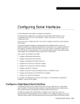
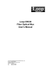
Figure 1 shows data flows for the various loopback modes.
Transmit and Receive Loopback Data Flows
Internal loopback
OC-12
Mux/
demux
Fiber
STTX
Internal loopback
STS-3
SUNI
622
Layer 3
routing
engine
Line
loopback
OC-12
11979
Figure 1
OC-12 Controller Loopback Mode
The OC-12 controller supports two loopback modes:
•
Internal—This loopback mode loops data from the transmit path to the receive path at the
mux/demux location on the line card, allowing diagnostics to send data to itself at the OC-12 level
without relying on external connections. In controller configuration mode, set the loopback mode to
internal, using the [no] loopback [internal | line ] configuration command:
Router(config-controller)# loopback internal
Router(config-controller)#
Use the no form of this command to restore the default value, no loopback.
Cisco IOS Release 12.0(8)S
12
Cisco IOS Software Configuration for the 1-Port Channelized OC-12/STM-4 (DS3) Line Card
How to Configure the 1-Port Channelized OC-12/STM-4 (DS3) Line Card
•
Line—This loopback mode loops data from the receive path to the transmit path at the mux/demux
part on the line card, returning all received data at the OC-12 level to the far end. In controller
configuration mode, set the loopback mode to line, using the [no] loopback [internal | line]
configuration command:
Router(config-controller)# loopback line
Router(config-controller)#
Use the no form of this command to restore the default value to no loopback.
DS3 Channel Loopback Mode
The DS3 channel supports three loopback modes:
•
Local—This loopback mode loops data from the transmit path to the receive path at the QJET
location on the line card, allowing diagnostics to send data to itself over a single channel without
relying on external connections. In serial interface configuration mode, set the loopback mode to
local, using the [no] loopback [local | network | remote ] configuration command, as in the
following example:
Router(config-if)# loopback local
Use the no form of this command to restore the default value, no loopback.
•
Network—This loopback mode loops data from the STS1 receive path to the STS1 transmit path at
the Mapper location on the line card, returning all received data over a single channel to the far end.
In controller configuration mode, set the loopback mode to local, using the
[no] loopback [local | network | remote ] configuration command:
Router(config-if)# loopback network
Use the no form of this command to restore the default value, no loopback.
•
Remote—This loopback mode sends an FEAC message over a single channel to the far end,
requesting that it transition into network loopback mode. In controller configuration mode, set the
loopback mode to local, using the [no] loopback [local | network | remote ] configuration
command, as in the following example:
Router(config-if)# loopback remote
Use the no form of this command to restore the default value, no loopback.
Configuring DS3 Port BER Testing
You can set one local DS3 serial port to bit error rate test (BERT) mode while the remaining local serial
ports continue to transmit and receive normal traffic. A BERT checks communication between the local
and the remote DS3 ports. If traffic is not being transmitted or received, create a back-to-back loopback
BER test and send out a predictable stream to ensure that you receive the same data that was transmitted.
To determine if the remote DS3 serial port returns the BERT pattern unchanged, the system administrator
for the remote router must manually set the remote DS3 serial port to loopback network line, while you
enter a bert pattern interface configuration command at specified time intervals on the local DS3 serial
port.
The following example shows the output from a back-to-back loopback BER test. The router types are
a Cisco 12012 Router on the local (near) end, and a Cisco 12008 Router on the remote (far) end.
Keepalive is disabled, while the loopback network line test runs between both routers. Clock source is
Cisco IOS Release 12.0(8)S
13
Cisco IOS Software Configuration for the 1-Port Channelized OC-12/STM-4 (DS3) Line Card
How to Configure the 1-Port Channelized OC-12/STM-4 (DS3) Line Card
set to internal on the local OC-12 controller in slot 1 with IP address 10.0.0.2. Clock source is set to
line on the remote OC-12 controller in slot 1 with IP address 11.0.0.1. A BERT pattern is entered
between local serial port 8/1 and remote serial port 5/1:
clock source internal----------clock source line
no keepalive-------------------loopback network line----------no keepalive
Router:[gsr-1]-----------------[mfr-1]
[BERT Pattern]
Serial8/1----------------------Serial5/1
[11.0.0.2]---------------------[11.0.0.1]
Router(config)# interface serial 6/0
Router(config-if)# bert pattern 2^23 interval 10
Router(config-if)#
Table 6 lists the BERT patterns, explains how to invoke them, and specifies test intervals between 1 and
1140 minutes long. The no bert pattern interface configuration command terminates an ongoing BER
test and returns the local and remote DS3 serial ports to the default value.
Table 6
DS3-Supported BERT Patterns
BERT Pattern
To Invoke
Command
2^15
A pseudorandom repeating pattern Router (config-if)# bert pattern 2^15 interval 10
that is 32767 bits long
2^20
A pseudorandom repeating pattern Router (config-if)# bert pattern 2^20 interval 10
that is 1048575 bits long
qrss 2^20
A quasirandom signal source
2^23
A pseudorandom repeating pattern Router (config-if)# bert pattern 2^23 interval 10
that is 8388607 bits long
Router (config-if)# bert pattern qrss
Checking Bit Errors Using a BERT
Following is an example of the bert pattern command and specified time intervals that will cause the
BERT to send the pseudorandom pattern 2^23 and repeat on the first DS3 channel for 10 minutes:
Router# configure terminal
Router(config)# interface serial 1/0:1
Router(config-if)# bert pattern 2^23 interval 10
Router(config-if)# end
Router(config)# end
Router#
Cisco IOS Release 12.0(8)S
14
Cisco IOS Software Configuration for the 1-Port Channelized OC-12/STM-4 (DS3) Line Card
How to Configure the 1-Port Channelized OC-12/STM-4 (DS3) Line Card
Entering Errors in BER Tests
To insert intentional errors into the BER test stream, use the following command syntax:
bert errors [no-of-errors], where the no-of-errors default is 1 and the range is 1 to 255, inclusive. The
following example shows the command used to insert five errors into the current BER test stream that is
running the pseudorandom pattern 2^23 that repeats on the first DS3 channel for 10 minutes:
Router# configure terminal
Router(config)# interface serial 1/0:1
Router(config-if)# bert pattern 2^23 interval 10
Router(config-if)# bert errors 5
Router(config-if)# end
Router(config)# end
Router#
Using show Commands to Verify BERT Configuration
When the DS3 serial port is running a BERT, the serial port state is down, and only BERT data is passed.
You can use the show commands shown in Table 7 to verify if the line card state is up or down.
Table 7
Show Commands for BERT Configuration
Commands
Explanation
show controller oc12 n/port:channel
Shows the current controller status, where n is the slot
number.
show controller oc12 1/0:1 bert
Shows the fields of a BER test that is still in progress.
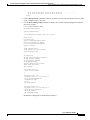
The following output indicates that BERT is enabled with a pattern of 2^23 and an interval of 10 minutes:
Router# show controller oc12 1/0:1 bert
Interface Serial1/0 (DS3 port 1)
BERT information:
State
:enabled (sync'd)
Pattern
:2^23
Interval
:10 minutes
Time remaining
:00:09:44
Total errors
:0
Time this sync
:00:00:10
Errors this sync :0
Sync count
:1
Router#
Note
The bit error test patterns from the serial ports on a 1-port channelized OC-12/STM-4
(DS3) line card are framed test patterns; therefore, they are inserted into the payload of a
framed T3 signal.
Cisco IOS Release 12.0(8)S
15
Cisco IOS Software Configuration for the 1-Port Channelized OC-12/STM-4 (DS3) Line Card
How to Configure the 1-Port Channelized OC-12/STM-4 (DS3) Line Card
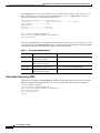
The following example shows the information of a BER test that is still in progress:
Router# show controller OC12 1/0:1 bert
Interface Serial1/0:1 (DS3 port 1)
BERT information:
State
:enabled (sync'd)
Pattern
:2^23
Interval
:10 minutes
Time remaining
:00:01:44
Total errors
:0
Time this sync
:00:08:10
Errors this sync :0
Sync count
:1
Router#
Note
When the DS3 is running a BERT, the Total Bit Errors value is not valid if the Status field
is Not Sync.
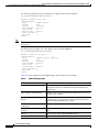
The following is an example of a screen display from a completed BER test:
Router# show controller OC12 1/0:1 bert
Interface Serial1/0:1 (DS3 port 1)
BERT information:
State
:disabled (sync'd, completed)
Pattern
:2^23
Interval
:10 minutes
Time remaining
:00:00:00
Total errors
:0
Time this sync
:00:09:54
Errors this sync :0
Sync count
:1
Router#
Table 8 provides explanations of the BERT display fields in the previous examples:
Table 8
BER Test Display Fields
BERT Information
Explanation
State: enabled (not synchronized)
BER test is active, but the hardware has not currently
synchronized. Errors are counted only when the hardware has
synchronized.
State: enabled (synchronized)
BER test is active, and the hardware has synchronized. Any errors
encountered are counted.
State: disabled (not synchronized,
failed)
BER test is finished and the test resulted in failure, either because
the hardware never synchronized or the physical layer interface
module (PLIM) declared the test a failure.
State: disabled (synchronized,
completed)
BER test is finished because the interval expired.
State: disabled (synchronized,
aborted)
BER test is finished as a result of a user request (for example, no
bert)
Pattern
Can be any one of the supported BERT patterns.
Interval
Can be any value from 1 to 1440 (units are in minutes).
Cisco IOS Release 12.0(8)S
16
Cisco IOS Software Configuration for the 1-Port Channelized OC-12/STM-4 (DS3) Line Card
Configuration Examples for the 1-Port Channelized OC-12/STM-4 (DS3) Line Card
Table 8
BER Test Display Fields (continued)
BERT Information
Explanation
Time remaining
Can be any value from 1 second to the interval provided,
formatted as hh:mm:ss.
Total errors
The total number of errors encountered while the hardware is
synchronized.
Time this synchronization
If the hardware is currently synchronized, the amount of time
since synchronization began, formatted as hh:mm:ss. If it is not
currently synchronized but was synchronized earlier, indicates
the amount of time that the last or most recent synchronization
period lasted, formatted as hh:mm:ss.
Errors this synchronization
If the hardware is currently synchronized, the number of errors
encountered during the current sync period. If it is not currently
synchronized but was synchronized earlier, the number of errors
encountered during the last or most recent synchronization
period.
Synchronization count
The number of times synchronization was achieved.
Configuration Examples for the 1-Port Channelized OC-12/STM-4
(DS3) Line Card
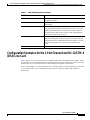
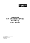
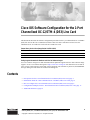
Figure 2 shows two 1-port channelized OC-12/STM-4 (DS3) line card configuration examples. In the
first example, the 1-port channelized OC-12/STM-4 (DS3) line card is channel 1 in router slot 1, and is
connected to a Cisco 7500 Series Router with an HSSI port through an external DSU.
In the second example, the 1-port channelized OC-12/STM-4 (DS3) line card is channel 5 in router slot
1, and is connected to a Cisco 7200 Series Router with a T3 serial port adapter with integrated
DSUs/CSUs.
Cisco IOS Release 12.0(8)S
17
Cisco IOS Software Configuration for the 1-Port Channelized OC-12/STM-4 (DS3) Line Card
Configuration Examples for the 1-Port Channelized OC-12/STM-4 (DS3) Line Card
Figure 2
1-Port Channelized OC-12/STM-4 (DS3) Line Card Interoperability Diagram
Cisco 7500
HSSI
DSU
DigitalLink
Larscom
Kentrox
Sonet Ring
Channel
#1
CHOC12 to DS3
#5
OC-12
ADM
ADM
Cisco 12000
ADM
PA-T3
Cisco 7200
CHOC12 to DS3
Cisco 12000
11741
ADM
DSU
PA-T3
Channel 1 (1/0:1)
Channel 5 (1/0:5)
Add Drop Multiplexer
Data Service Unit
T3 Serial port adapter
with integrated CSU/DSU
DS3
The following example shows a typical configuration for a channel, associated with a 1-port channelized
OC-12/STM-4 (DS3) line card, that is connected to a Cisco 7200 Series Router with a T3 serial port
adapter (see Figure 2):
Router# configure terminal
Router(config)# interface serial 1/0:5
Router(config-if)# dsu mode cisco
Router(config-if)# dsu bandwidth 44210
Router(config-if)# framing c-bit
Router(config-if)# no scramble
Router(config-if)# crc 16
Router(config-if)# keepalive
Router(config-if)# ip address 1.1.5.1 255.255.255.0
Router(config-if)# no shutdown
Cisco IOS Release 12.0(8)S
18
Cisco IOS Software Configuration for the 1-Port Channelized OC-12/STM-4 (DS3) Line Card
Additional References
Additional References
The following sections provide references related to the 1-port channelized OC-12/STM-4 (DS3) line
card.
Related Documents
Related Topic
Document Title
Hardware installation
Channelized and Electrical Interface Line Card Installation and
Configuration
Software configuration commands
•
Software Configuration Guide for the Cisco 12000 Series
Internet Router
•
Cisco IOS Configuration Fundamentals Configuration Guide
•
Cisco IOS Release 12.0S Release Notes for Cisco 12000 Series
Internet Routers
Technical Assistance
Description
Link
Technical Assistance Center (TAC) home page,
containing 30,000 pages of searchable technical
content, including links to products, technologies,
solutions, technical tips, and tools. Registered
Cisco.com users can log in from this page to access
even more content.
http://www.cisco.com/public/support/tac/home.shtml
CCVP, the Cisco logo, and Welcome to the Human Network are trademarks of Cisco Systems, Inc.; Changing the Way We Work, Live, Play, and Learn is
a service mark of Cisco Systems, Inc.; and Access Registrar, Aironet, Catalyst, CCDA, CCDP, CCIE, CCIP, CCNA, CCNP, CCSP, Cisco, the Cisco
Certified Internetwork Expert logo, Cisco IOS, Cisco Press, Cisco Systems, Cisco Systems Capital, the Cisco Systems logo, Cisco Unity,
Enterprise/Solver, EtherChannel, EtherFast, EtherSwitch, Fast Step, Follow Me Browsing, FormShare, GigaDrive, HomeLink, Internet Quotient, IOS,
iPhone, IP/TV, iQ Expertise, the iQ logo, iQ Net Readiness Scorecard, iQuick Study, LightStream, Linksys, MeetingPlace, MGX, Networkers,
Networking Academy, Network Registrar, PIX, ProConnect, ScriptShare, SMARTnet, StackWise, The Fastest Way to Increase Your Internet Quotient,
and TransPath are registered trademarks of Cisco Systems, Inc. and/or its affiliates in the United States and certain other countries.
All other trademarks mentioned in this document or Website are the property of their respective owners. The use of the word partner does not imply a
partnership relationship between Cisco and any other company. (0711R)
Copyright © 2004 Cisco Systems, Inc. All rights reserved.
Cisco IOS Release 12.0(8)S
19
Cisco IOS Software Configuration for the 1-Port Channelized OC-12/STM-4 (DS3) Line Card
Additional References
Cisco IOS Release 12.0(8)S
20