1
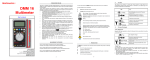
ENGLISH
User manual
1.800.561.8187
© Copyright HT ITALIA 2010
www.
.com
[email protected]
Versione EN 1.02 - 13/12/2010
HT9012
Contents:
1
SAFETY PRECAUTIONS AND PROCEDURES ..........................................................2
1.1
1.2
1.3
1.4
2
GENERAL DESCRIPTION ...........................................................................................4
2.1
2.2
3
4.1.1
4.1.2
4.2
4.2.1
4.2.2
4.2.3
4.2.4
4.2.5
4.3
4.3.1
4.3.2
4.3.3
4.3.4
4.3.5
Commands description............................................................................................................... 6
Alignment marks......................................................................................................................... 6
Function key description.................................................................................................... 7
HOLD key ................................................................................................................................... 7
key ........................................................................................................................................ 7
RANGE key ................................................................................................................................ 7
MAX key ..................................................................................................................................... 7
MODE key .................................................................................................................................. 7
Functions of rotary switch description ............................................................................... 8
DC Voltage measurement .......................................................................................................... 8
AC Voltage measurement .......................................................................................................... 9
AC Current measurement......................................................................................................... 10
Resistance measurement......................................................................................................... 11
Continuity test and Diode test................................................................................................... 12
General informations ....................................................................................................... 13
Battery replacement ........................................................................................................ 13
Cleaning .......................................................................................................................... 13
End of life ........................................................................................................................ 13
TECHNICAL SPECIFICATIONS ................................................................................14
6.1
6.1.1
6.1.2
6.2
6.2.1
6.3
6.3.1
7
Instrument description ....................................................................................................... 6
MAINTENANCE .........................................................................................................13
5.1
5.2
5.3
5.4
6
Initial .................................................................................................................................. 5
Power supply..................................................................................................................... 5
Calibration ......................................................................................................................... 5
Storage.............................................................................................................................. 5
OPERATING INSTRUCTIONS.....................................................................................6
4.1
5
TRMS and Mean Value measuring instruments................................................................ 4
True Root Mean Square value and crest factor definitions ............................................... 4
PREPARATION FOR USE ...........................................................................................5
3.1
3.2
3.3
3.4
4
Preliminary ........................................................................................................................ 2
Before use ......................................................................................................................... 3
After use ............................................................................................................................ 3
Measuring (overvoltage) categories definitions................................................................. 3
Characteristics................................................................................................................. 14
Safety........................................................................................................................................ 15
General data ............................................................................................................................. 15
Environmental conditions ................................................................................................ 15
Climatic conditions.................................................................................................................... 15
Accessories ..................................................................................................................... 15
Standard accessories ............................................................................................................... 15
SERVICE....................................................................................................................16
7.1
7.2
Warranty conditions......................................................................................................... 16
Service ............................................................................................................................ 16
1.800.561.8187
www.
.com
EN - 1
[email protected]
HT9012
1 SAFETY PRECAUTIONS AND PROCEDURES
This clamp complies with IEC/EN61010-1. For your own safety and in order to avoid
damaging the instrument, you’re recommended to keep to the instructions contained in this
manual and read carefully all the notes preceded by the symbol .
Take extreme care for the following conditions while measuring:
• Do not measure voltage or current in humid or wet environment
• Do not use the meter in presence of explosive gas (material), combustible gas
(material), steam or dust
• Insulate yourself from the object to be tested
• Do not touch exposed metal (conductive) parts such as test lead ends, sockets, fixing
objects, circuits, etc
• If you detect anomalies of testing end (metal part) and attachment of the meter such as
breakages, deformations, foreign substances, no display, etc., do not take any
measurement
• Measuring voltage over 20V as it might cause human body electricity conduction
The followings symbols are used:
Caution: refer to the instruction manual. An incorrect use may damage the tester
or its components
High Voltage ranger: electrical shock risk
Double insulated instrument
AC Voltage or Current
DC Voltage
Ground reference
1.1 PRELIMINARY
• This apparatus has been designed for use in an environment of pollution degree 2.
Indoor use
• It measures CURRENT and VOLTAGE on CAT IV 600V to ground plants. For
overvoltage categories please see § 1.4
• You must comply with the usual safety regulations aimed at trotecting you against the
dangerous electric current and protecting the instrument against an incorrect operation
• Only the leads supplied with the instrument guarantee compliance with the safety
standard. They must be in good conditions and they must be replaced, if necessary,
with an identical model
• Do not test or connect to any circuit whose voltage or current exceeds the specified
overload protection
• Do not perform any test at environmental conditions exceeding the limits indicated
• Make sure that the battery are installed correctly
• Before connecting the test probes to the installation, check that the function selector is
positioned on the required measurement
• Make sure that the LCD and
the rotate switch
www.
.comshow the same as the function desired
EN - 2
1.800.561.8187
[email protected]
HT9012
1.2 BEFORE USE
Always keep to the instructions contained in this manual:
CAUTION
Non compliance with the warnings and/or the instructions may damage the
tester and/or its components or injure the operator.
•
•
•
•
•
•
•
Before changing the switch’s position, take off the clamp jaw from the tested conductor
or the electrical circuit in order to avoid any accident
When the clamp is connected to the circuits to be tested, never touch unused terminals
When testing resistors, do not add voltage. Although there is a protection circuit,
excessive voltage would cause malfunctioning
Before measuring current, remove the voltage-resistance test leads
When measuring current, any strong current near or close to the clamp jaw will affect
the accuracy
When measuring current, always put the tested conductor in the middle of the clamp
jaw in order to obtain a more accurate reading
If the reading value or the sign indication remains unchanged during the measurement,
check if the HOLD function is active
1.3 AFTER USE
• Once the measurements are completed, turn the rotary switch to OFF
• If you expect not to use the clamp for a long time, remove the battery
1.4 MEASURING (OVERVOLTAGE) CATEGORIES DEFINITIONS
The norm IEC/EN61010-1: Safety requirements for electrical equipment for measurement,
control and laboratory use, Part 1: General requirements, defines what measuring
category, usually called overvoltage category, is. On § 6.7.4: Measuring circuits, it says:
(OMISSIS)
circuits are divided into the following measurement categories:
•
•
•
•
Measurement category IV is for measurements performed at the source of the lowvoltage installation
Examples are electricity meters and measurements on primary overcurrent protection
devices and ripple control units
Measurement category III is for measurements performed in the building installation
Examples are measurements on distribution boards, circuit breakers, wiring, including
cables, bus-bars, junction boxes, switches, socket-outlets in the fixed installation, and
equipment for industrial use and some other equipment, for example, stationary
motors with permanent connection to fixed installation
Measurement category II is for measurements performed on circuits directly
connected to the low voltage installation
Examples are measurements on household appliances, portable tools and similar
equipment
Measurement category I is for measurements performed on circuits not directly
connected to MAINS
Examples are measurements on circuits not derived from MAINS, and specially
protected (internal) MAINS-derived circuits. In the latter case, transient stresses are
variable; for that reason, the norm requires that the transient withstand capability of the
equipment is made known
to the user .com
www.
EN - 3
1.800.561.8187
[email protected]
HT9012
2 GENERAL DESCRIPTION
HT9012 meter can performs the herewith measurements:
•
•
•
•
•
DC and AC voltage
Detection of AC voltage without contact
AC current
Resistance and test continuity
Diode test
Each parameter can be selected by rotating the 8-positions switch included OFF position.
key to
To abilitate the hold function the HOLD key is available. There are also
activate/desactivate the display backlight, the RANGE key for manual selction of
measurement ranges, the MAX key for maximum value measurement of some parameters
and the MODE key for the selection of different features common at the same position of
selector rotation. The selected quantity appears on a high-contrast liquid crystal display
with indication of measurement units and functions. The instrument disposes of an Auto
Power Off function consisting in an automatic switching off 15 minutes after last selector
rotation.
2.1 TRMS AND MEAN VALUE MEASURING INSTRUMENTS
Safety testers for alternate quantities are divided into two big families:
• MEAN VALUE instruments: instruments which measure only the value of the wave at
the fundamental frequency (50 or 60 Hz)
• TRUE ROOT MEAN SQUARE instruments, also defined as TRMS: instruments which
measure the true root mean square value of the quantity under test
In presence of a perfectly sinusoidal wave, both families provide identical results. In
presence of distorted waves, instead, the readings are different. Mean value instruments
provide only the value of the fundamental wave while True RMS instruments provide the
value of the entire wave, including harmonics (within the passband of the instrument).
Accordingly, if the same quantity is measured with both kinds of instruments, the
measured values are identical only if the wave is purely sinusoidal. Should it be distorted,
True RMS instruments provide higher values than medium value instruments.
2.2 TRUE ROOT MEAN SQUARE VALUE AND CREST FACTOR DEFINITIONS
The current effective value is defined as follows: “In an interval of time equivalent to a
period, an alternate current with effective value having an intensity of 1A, by passing on a
resistor, disperses the same energy which would be dispersed in the same period of time
by a direct current having an intensity of 1A”. From this definition comes the numerical
1
expression: G=
T
t 0 +T
∫g
2
(t )dt The effective value is indicated as RMS (root mean square).
t0
The Crest Factor is defined as the ratio between the Peak Value of a signal and its
Gp
. This value varies according to the waveform of the signal,
effective value: CF (G)=
G RMS
for a purely sinusoidal wave it’s worth 2 =1.41. In presence of distortions the Crest Factor
assumes higher values as long as the wave distortion is higher.
1.800.561.8187
www.
.com
EN - 4
[email protected]
HT9012
3 PREPARATION FOR USE
3.1 INITIAL
The tester has been checked from a mechanical and electrical point of view before
shipment.
Every care has been taken to make sure that the instrument reaches you in perfect
conditions.
However, it’s advisable to make a rapid check in order to detect eventual damages which
may have occurred in transit. Should this be the case, enter immediately the usual claims
with the carrier.
Make sure that all the accessories listed in § 6.3.1 are contained in the package. In case of
discrepancies contact the dealer.
In case of returning of the tester please keep to the instructions given in § 7.
3.2 POWER SUPPLY
The instrument is battery supplied. One battery 9V IEC 1604 NEDA 6F22 are included in
the package. When battery is low, the symbol “
” appears on the display. Replace it
immediately, following the instructions given in § 5.2.
The instrument disposes of the Auto Power OFF function (not disable) consisting in an
automatic switching off 15 minutes of idleness.
3.3 CALIBRATION
The tester complies with the technical features listed in this manual. Its performances are
guaranteed for one year.
3.4 STORAGE
In order to guarantee the accuracy of the measurements, after a period of storage in
extreme environmental condition, wait for the necessary time so that the tester returns to
normal measuring conditions (see environmental specifications, § 6.2.1).
1.800.561.8187
www.
.com
EN - 5
[email protected]
HT9012
4 OPERATING INSTRUCTIONS
4.1 INSTRUMENT DESCRIPTION
4.1.1 Commands description
LEGEND:
1. Clamp jaw
2. Red LED for AC voltage
detection without contact
3. Clamp trigger
4. Rotary function selector
5. HOLD key
backlight key
6.
7. LCD display
8. MODE key
9. MAX key
10. RANGE key
11. COM input jack
12. VΩ
input jack
13. Battery cover
Fig. 1: Instrument description
4.1.2 Alignment marks
Put the conductor within the jaws on intersection of the indicated marks as much as
possible (see Fig. 2) in order to meet the meter accuracy specifications
LEGEND
1. Alignment marks
2. Conductor
1.800.561.8187
Fig. 2: Alignment marks
www.
.com
EN - 6
[email protected]
HT9012
4.2 FUNCTION KEY DESCRIPTION
4.2.1 HOLD key
By pushing HOLD key the parameter’s measured value is frozen on the display and the
symbol “HOLD” appears on it. Pushing HOLD key another time deactivates this mode.
key
4.2.2
By pushing and hold
key for about 1s it’s possible to activate the backlight function on
key again for about 3s to exit from the function or
the display. By pressing and hold
waiting the automatically disable after about 20 seconds. The function is available on each
position of the rotary selector.
4.2.3 RANGE key
By pushing RANGE key, the manual mode is activated and the “AUTO” symbol
disappears from the display. Press RANGE cyclically to change the measuring range and
fix the decimal point on the display. For reading more than the maximum range the “OL”
indication is shown at display. To exit this function keep RANGE key pressed for at least 1
second or rotate the selector to another position. This feature is disabled for AC current
diode test and continuity test measurements.
4.2.4 MAX key
By pushing MAX key, maximum value are measured. The symbol corresponding “MAX” is
displayed. This value is stored and automatically updated as soon as an higher value is
measured by meter. Press MAX key again or rotate the selector to another position to exit
from this function. This feature is disabled for resistance, diode test and continuity test
measurements.
4.2.5 MODE key
By pushing MODE key the selection of a double measured functions which are present at
display is possible. In particular this key is active only in Ω / position to select among
resistance test, diode test and continuity test.
1.800.561.8187
www.
.com
EN - 7
[email protected]
HT9012
4.3 FUNCTIONS OF ROTARY SWITCH DESCRIPTION
4.3.1 DC Voltage measurement
CAUTION
Maximum input for AC Voltage measurements is 1000VDC or
1000VACrms. Do not take any voltage measurement exceeding this limit in
order not to risk electrical shock or damaging the meter.
Fig. 3: Taking DC voltage measurement
1. Rotate the switch on V
position. The “DC” symbol is shown at display
2. Pressing the RANGE key to select the correct range or using the Autorange feature
(see § 4.2.3). If the voltage value under test is unknown, select the highest range
3. Insert the red test lead plug into VΩ
jack and the black test lead plug into COM
jack
4. Connect the two long ends of test leads to the desired circuit (see Fig. 3) then reading
will be displayed
5. “OL” message is shown at display if the DC voltage under test is over the maximum
value that the instrument is able to measure
6. The “-“ symbol at display means that the voltage have an opposite sign respect the
connection of Fig. 3)
7. For HOLD and MAX features please refer to § 4.2
1.800.561.8187
www.
.com
EN - 8
[email protected]
HT9012
4.3.2 AC Voltage measurement
CAUTION
Maximum input for AC Voltage measurements is 1000VDC or
1000VACrms. Do not take any voltage measurement exceeding this limit in
order not to risk electrical shock or damaging the meter.
Fig. 4: Taking AC voltage measurement
1. Approach the meter closest to AC source and note the turn on of red LED which is
placed to the bottom of clamp jaws (see Fig. 1 – part 2) which detect the AC voltage
2. Rotate the switch on V position. The “AC” symbol is shown at display
3. Pressing the RANGE key to select the correct range or using the Autorange feature
(see § 4.2.3). If the voltage value under test is unknown, select the highest range
4. Insert the red test lead plug into VΩ
jack and the black test lead plug into COM
jack (see Fig. 4)
5. Connect the two long ends of test leads to the desired circuit (see Fig. 4) then reading
will be displayed
6. “OL” message is shown at display if the AC voltage under test is over the maximum
value that the instrument is able to measure
7. For HOLD and MAX functions please refer to § 4.2
1.800.561.8187
www.
.com
EN - 9
[email protected]
HT9012
4.3.3 AC Current measurement
CAUTION
Make sure that all the test leads are disconnected from the meter terminals
for current measurement.
Fig. 5: Taking AC current measurement
1. Approach the meter closest to AC source. The turn on of red LED which is placed to
the bottom of clamp jaws (see Fig. 1 – part 2) detect the AC voltage
2. Rotate the switch on position on a measurement range between 2A
and 600A . If
the current value under test is unknown, select the highest range
3. Put the conductor to be tested inside to the center of clamp jaw to perform accurated
measurements. Consider the notches on jaws as reference (see Fig. 2). The current
value is shown at display
4. “OL” message is shown at display the current under test is over the maximum value
that the instrument is able to measure
5. For HOLD and MAX functions please refer to § 4.2
1.800.561.8187
www.
.com
EN - 10
[email protected]
HT9012
4.3.4 Resistance measurement
CAUTION
Before taking any in circuit resistance measurement, remove power from
the circuit to be tested and discharge all the capacitors.
Fig. 6: Taking resistance measurement
1. Rotate the switch on Ω
position. The “Ω” symbol is shown at display
2. Pressing the RANGE key to select the correct range or using the Autorange feature
(see § 4.2.3). If the resistance value under test is unknown, select the highest range
3. Insert the red test lead plug into VΩ
jack and the black test lead plug into COM
jack
4. Connect the two long ends of test leads to the desired circuit (see Fig. 6) then reading
value of resistance will be displayed
5. When “OL” symbol is displayed, the resistance under test is over the maximum value
that the instrument is able to measure
6. For HOLD function please refer to § 4.2
1.800.561.8187
www.
.com
EN - 11
[email protected]
HT9012
4.3.5 Continuity test and Diode test
CAUTION
Before taking any in circuit resistance measurement or diode test, remove
power from the circuit to be tested and discharge all the capacitors.
Fig. 7: Taking continuity test and diode test
position
1. Rotate the switch on Ω
2. Pushing MODE key and select continuity test. The symbol is shown at display
3. Insert the red test lead plug into VΩ
jack and the black test lead plug into COM
jack and perform continuity test on the object on test (see Fig. 7 – left side). Buzzer
emits sound if the measured resistance value is less about 100Ω
4. Pushing MODE key and select diode test. The “ ” symbol is shown at display
5. Connect the red test leads to the anode of diode on test and the black test lead on the
cathode ones (see Fig. 7 – right side)
6. Displayed values within 0.4V and 0.7V (direct junction) and “OL” (reverse junction) are
correspondent to a correct result. A “0mV” value means a shorted device while a “OL”
indication in both side means a broken device
1.800.561.8187
www.
.com
EN - 12
[email protected]
HT9012
5 MAINTENANCE
5.1 GENERAL INFORMATIONS
1. This digital clamp meter is a precision instrument. Whether in use or in storage, please
do not exceed the specification requirements to avoid possible damages or dangers
2. Do not place this meter at high temperatures or humidity or expose it to direct sunlight
3. Be sure to turn off the meter after use. If you expect not to use the tester for a long
time, remove the battery in order to avoid leakages of battery liquid that would damage
the internal parts
5.2 BATTERY REPLACEMENT
When “
” symbol appears on the display, replace the battery
CAUTION
Only expert and trained technicians must perform this operation. Remove
the test leads or the conductor under test before replacing the battery.
1. Rotate the switch on OFF
2. Remove the test leads or the objects to be tested
3. Remove the screw from the battery cover, and detach the battery cover from the
bottom cover
4. Remove the battery
5. Replace the battery with a same type new one
6. Replace the battery cover and screw
7. Use the appropriate battery disposal methods for Yr area
5.3 CLEANING
For cleaning the instrument use a soft dry cloth. Never use a wet cloth, solvents or water,
etc.
5.4
END OF LIFE
CAUTION: this symbol indicates that equipment, battery and its accessories
shall be subject to a separate collection and correct disposal.
1.800.561.8187
www.
.com
EN - 13
[email protected]
HT9012
6 TECHNICAL SPECIFICATIONS
6.1 CHARACTERISTICS
Accuracy is calculated as [% rdg + (n°of dgt) * resolution] referred to: 23°C ± 5°C <80%RH
DC Voltage
Range
Resolution
Accuracy
Input
impedance
Overload
protection
200.0mV
2.000V
20.00V
200.0V
1000V
0.1mV
0.001V
0.01V
0.1V
1V
±(1.0%rdg + 3dgt)
10MΩ
1000VDC/ACrms
Input
impedance
Overload
protection
10MΩ
1000VDC/ACrms
The meter emits a continuous sound with VDC >1000V
AC Voltage
Range
Resolution
200.0mV
2.000V
20.00V
200.0V
1000V
0.1mV
0.001V
0.01V
0.1V
1V
Accuracy
(50 ÷ 60Hz)
±(1.5%rdg + 15dgt)
±(1.0%rdg + 4dgt)
Integrated sensor for AC voltage detection: LED turn on for phase-earth voltage > 100V, 50/60Hz
The meter emits a continuous sound on 1000V range for VAC>750V
AC Current
Range
Resolution
Accuracy (*)
2.000A
20.00A
200.0A
600A
0.001A
0.01A
0.1A
1A
±(2.5%rdg + 10dgt)
±(2.5%rdg + 4dgt)
Frequency
range
Overload
protection
50÷60Hz
600Arms
Buzzer
Overload
protection
≤100Ω
600VDC/ACrms
±(3.0%rdg + 4dgt)
(*) Referred to cable inside to the center of clamp jaws
Position sensitivity: ±2.0%rdg
Resistance and Continuity test
Range
Resolution
200.0Ω
2.000kΩ
20.00kΩ
200.0kΩ
2.000MΩ
20.00MΩ
0.1Ω
0.001kΩ
0.01kΩ
0.1kΩ
0.001MΩ
0.01MΩ
Accuracy
±(1.0%rdg + 5dgt)
±(2.0%rdg + 10dgt)
Diode test
Features
1.800.561.8187
Test current
0.3mA typical
www.
.com
EN - 14
Open voltage
1.5VDC
[email protected]
HT9012
6.1.1 Safety
Comply with:
Insulation:
Pollution degree:
For inside use, max height:
Installation category:
IEC/EN 61010-1
double insulation
2
2000m (6562 ft)
CAT IV 600V, CAT III 1000V to ground
6.1.2 General data
Mechanical characteristics
Dimensions (L x W x H):
Weight (including battery):
Max conductor size:
215 x 74 x 43mm ; 8 x 3 x 2 in
285g (10 ounces)
30mm (1in)
Supply
Battery type:
Low battery indication:
AutoPowerOFF
1x9V alkaline battery NEDA 1604 IEC 6F22
” is displayed when the battery level is too low
“
after 15min of idleness (not disabled)
Display
Characteristics:
3½ LCD (max 2000 points) plus decimal point, unit
symbol indication and backlight
2 times/sec
Mean value
Sample rate:
Conversion mode:
6.2 ENVIRONMENTAL CONDITIONS
6.2.1 Climatic conditions
Reference temperature:
23° ± 5°C (73°F ± 41°F)
Operating temperature:
5 ÷ 40°C (41°F ÷ 104°F)
Operating humidity:
<80%RH
Storage temperature:
-20 ÷ 60 °C (-4°F ÷ 140°F)
Storage humidity:
<80%RH
This product conforms to the prescriptions of the European directive on low voltage
2006/95/EEC and to EMC directive 2004/108/EEC
6.3 ACCESSORIES
6.3.1 Standard accessories
The content of a standard package is the following:
• Instrument HT9012
• Test leads - Cod. 4413-2
• Carrying bag
• Battery
• User manual
1.800.561.8187
www.
.com
EN - 15
[email protected]
HT9012
7 SERVICE
7.1 WARRANTY CONDITIONS
This instrument is guaranteed against material or production defects, in accordance with
our general sales conditions. During the warranty period the manufacturer reserves the
right to decide either to repair or replace the product.
Should you need for any reason to return back the instrument for repair or replacement
take prior agreements with the local distributor from whom you bought it. Do not forget to
enclose a report describing the reasons for returning (detected fault). Use only original
packaging. Any damage occurred in transit due to non original packaging will be charged
anyhow to the customer.
The manufacturer will not be responsible for any damage to persons or things.
The warranty doesn’t apply to:
• Accessories and batteries (not covered by warranty).
• Repairs made necessary by improper use (including adaptation to particular
applications not foreseen in the instructions manual) or improper combination with
incompatible accessories or equipment.
• Repairs made necessary by improper shipping material causing damages in transit.
• Repairs made necessary by previous attempts for repair carried out by non skilled or
unauthorized personnel.
• Instruments for whatever reason modified by the customer himself without explicit
authorization of our Technical Dept.
The contents of this manual cannot be reproduced in any form without our authorization.
Our products are patented. Our logotypes are registered. We reserve the right to
modify characteristics and prices further to technological developments.
7.2 SERVICE
Shouldn’t the instrument work properly, before contacting your distributor make sure that
battery is correctly installed and working, check the test leads and replace them if
necessary. Make sure that your operating procedure corresponds to the one described in
this manual.
Should you need for any reason to return back the instrument for repair or replacement
take prior agreements with the local distributor from whom you bought it. Do not forget to
enclose a report describing the reasons for returning (detected fault). Use only original
packaging. Any damage occurred in transit due to non original packaging will be charged
anyhow to the customer.
The manufacturer will not be responsible for any damage to persons or things.
1.800.561.8187
www.
.com
EN - 16
[email protected]