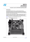
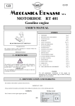
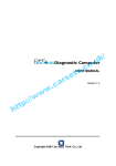
1
TESTING
After wiring the rudder angle sensor, Rudder Angle Indicator and then check that all
wiring conforms to what is shown in Figure 6, switch on the master switch or breaker
supplying power to the rudder angle indicator system. Move the rudder to determine
if the rudder angle indicator move in the correct direction. If the rudder angle indicator
moves the wrong direction, reverse the white and red wires coming from the rudder
angle sensor to the rudder angle indicator.
RUDDER ANGLE INDICATOR SYSTEM
RAI-S series
Figure 6
ADJUSTMENTS :
Move the rudder to the dead ahead position. If the deal ahead is precisely known and the
Rudder Angle Indicator is off, adjust the length of linkage by rotating the ball joints on the
both ends of the linkage. Move the rudder to hard over port and starboard and check the
indication is as expected.
Two factory pre-calibrated trim controls are provided on the rear of rudder angle indicator
•The offset control allows some adjustment of the dead ahead rudder indication, making
it easier to adjust the system while on sea trials. If the indication is more than 10 degree
off, adjust the rudder angle sensor linkage rather than the offset trim control.
•The span control allows some adjustment of the Rudder Angle Indicator indication at
the hard over rudder position. This system is calibrated at the factory to be accurated
within 3 degree if installed as per instruction. If the Rudder Angle Sensor linkage
geometry is not correct ( rudder tiller arm and rudder angle sensor arm are not equal in
height, parallel or linkage rod is not 90 degrees when centered), indication of the hard
over positions will be off. It is better to correct the linkage but, if this is not possible, the
span control can be used. Making a large correction for the linkage problem by using
the span control can introduce errors in indication at the half deflection position and
unequal indication at the hard over position.
SEAFIRST ENGINEERING CO
Address : 205, 1735-1, Song Jung Dong,
Gang Seo Gu, Busan, Korea.
Tel : 82-51-831-1640
Fax : 82-51-831-1641
http://www.seafirst .co.kr
GENERAL
Seafirst Rudder Angle Indicator ( RAI-S ) System consists of a Rudder Angle Sensor and
Rudder Angle Indicator. This system ( RAI-S) is suitable to install only one Seafirst Rudder
Angle Indicator.
RUDDER ANGLE SENSOR
Rudder Angle Indicator
1) Rudder Angle Sensor is installed in the stern of the vessel, close to tiller arm.
2) A mounting base may have to be fabricated by installer to position the rudder angle
sensor properly.
3) Mount the linkage supplied with the rudder angle sensor at 90 degree from tiller arm like
Figure 2. Bolt the ball joint to the tiller arm.
4) The rudder angle sensor arm is same height “A” as the rudder tiller arm “A” like Figure 2.
5) “B” dimension should be same like Figure 2
Operating Power : 8V-36VDC
Dimmer Switch to adjust brightness
Additional terminal for ON-OFF of LED light function
Span : To adjust a maximum angle
Offset : To adjust a center angle
DNR 104 indicator by itself can be mounted simply by drilling 86mm hole and securing
with supplied mounting bracket
Figure 2 :
Installation of Rudder Angle Sensor
Figure 4 : DNR-104
DNR 104P indicator is supplied with SS plate. Bolt on 4 hole on the plate
Figure 3 : Dimension of Rudder Angle Sensor
Figure 1 : RAI-S system
•Rudder Angle Indicator : DNR-104, DNR-104P
•Rudder Angle Sensor : DSR-110
If the locking screw in the rudder angle sensor arm has been loosened, or the arm
removed from the rudder angle sensor, re-attached the arm and check the potentiometer.
When the rudder is dead ahead, the electrical resistance between the black wires and
the white, should be 2.5k ohms. The potentiometer can also be centered mechanically be
aligning the notch on the sensor shaft. Careful to check the installation for any mechanical
obstructions or binding of the linkage, and correct it now, before it becomes a problem.
The rudder angle sensor is supplied with 10 meter of shield cable. Run the cable from the
rudder angle sensor towards the rudder angle indicator, ensuring that it is protected by a
hose or conduit wherever it passes through fish or cargo holds, or any other area where it
could be damaged.
Figure 5 : DNR-104P