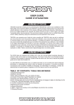
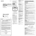
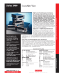
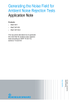
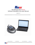
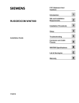
1
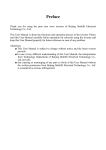
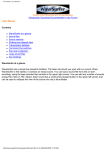
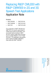
ST 052
Multi-Zonal Remote Radiomonitoring System
Specifications and the User’s Guide
1. Introduction
This User’s Guide contains information necessary for the setup and operation of the ST 052.
Before operating your ST 052, read this User’s Guide carefully and consult it every time you
have questions about the operation of device.
The information in this User’s Guide is subject to change without prior notice.
The manufacturer has a right to change the product’s specifications in such a manner that they
do not worsen or reduce the product’s functionality.
2. Purpose and general description
The main purpose of the ST 052 is the detection of the unauthorized use of equipment for
wireless transmission of audio and video information.
The ST 052 comprises remote modules (hereafter, “M”) that are placed in locations where the
use of unauthorized radio transmission devices is suspected.
A single M covers a local zone* and monitors the electromagnetic situation within it.
The M receiver consists of two blocks: a high-speed scanning receiver with a frequency range of
70–1,200 MHz and a wideband field detector with a frequency range of 900–6,000 MHz.
Via a radio channel, data from M is transmitted to a base transceiver station connected to a PC.
The range of stable radio exchange of the ST 052 is up to 100** meters in buildings and up to
1,000 meters in open areas.
The maximum number of simultaneously operating Ms is 32. Generally, this number is
determined by the ability of the monitor to display the necessary information and scanning
intervals of M (see “Timing of Data Transmission Between M and the Base Station”).
The specialized software allows for controlling the system and displays information from M on a
computer monitor.
The following information can be displayed: alarm signal, signal level, data transfer protocols
(GSM, DECT, Bluethooth, WLAN), and spectrogram (with a frequency range of 70–1,200 MHz).
In addition, the system logs the events to a log file.
Advanced settings allow for finer customized setup of the system to suit the requirements of
the particular location.
*A local zone is space limited by the sensitivity of the scanning receiver and field detector of M
and interference in the zone of monitoring.
**This number may vary over a wide range depending on the structure of the building,
interference, and transmission frequency.
3. Box contents
1.
2.
3.
4.
5.
6.
7.
8.
9.
Remote module (M)
Base transceiver station
Installation disc with software
Data cable for the base station
Transceiver antenna for the base station
Transceiver antenna for M
Receiver antenna for the field detector of M
Receiver antenna for the scanning receiver of M
Power adapter for M
*depending on the number of M
1–32*
1
1
1
1
1–32*
1–32*
1–32*
1–32*
4. Description
4.1. Remote module
M consists of the following basic components:
—high-speed scanning receiver (70–1,200 MHz);
—wideband field detector (1,200–6,000 MHz);
—controls block;
—radiomodem:
—power adapter.
The high-speed scanning receiver is a superheterodyne receiver with a high intermediate
frequency, intended for detecting stable (non-pulse) signals.
The field detector can receive wideband signals, measure the levels of the direct and pulse
components, and identify GSM, DECT, Bluethooth, and WLAN (802.11) signals.
WARNING! The output amplifier of M may be damaged by high voltage from static electricity,
which may accumulate on synthetic clothing, floor carpets, etc.
The controls block carries out preliminary processing of data and the general operation of M.
The radiomodem is used for transmitting and receiving data in the radio frequency range to and
from the base station.
On the top of M your will find:
—ports for connecting antennas of the scanning receiver (ANT1), field detector (ANT2), and
radiomodem (ANT3);
—two LEDs that indicate the state of M, marked PWR and TX.
—M ID DIP switch lid (see. Additional Information).
The side of the module has a power switch and a port for connecting the power adapter,
marked DC 5V.
4.1.1. Power supply of M
The remote module can be powered by a power adapter or by a built-in Li-Ion rechargeable
battery.
During normal operation the unit will be powered by the power adapter.
A fully charged battery will provide sufficient power for an uninterrupted normal operation of
the module for at least 10 hours, and at lest one months in standby mode (software not
running, the unit turned on).
4.1.2 Charging the battery
To charge the battery, connect the power adapter to the unit and switch it on.
The battery charges while the unit is operated from the power adapter.
Use the CHARGE LED to monitor charging:
—a brightly lit LED indicates a discharged battery;
—a dim LED indicates that the battery is charged or is charging if the unit is powered by the
power adapter.
To determine the battery level, look at the battery level indicator (see 5 in Fig. 1).
It takes approximately 3 hours to charge the battery to its full capacity.
4.2. Base transceiver station
The base station consists of the following basic blocks:
—radiomodem;
—preliminary data processing block;
—USB interface for connecting the base station to a PC.
On the top panel of the base station you will find ports for connecting the radiomodem antenna
(ANT) and LEDs indicating the station’s states: PWR and TX.
On the side panel you will find the USB port and the unit’s serial number.
5. Packaging
For transporting and storing the accessories and parts of the system are packed in boxes made
from white corrugated cardboard with the dimensions 170 x 150 x 60 mm (6.7 x 5.9 x 2.4 in).
6. Turning on the ST 052 for the first time
6.1. Preparing the system
Attach antennas to M and the base station using the following as a guide:
—use ANT port on the base station to attach antenna 1;
—use ANT1 port to attach antenna 1, ANT2 to attach antenna 2, and ANT3 to attach antenna 3.
Plug the power adapter into a 220VA power outlet.
Plug the power adapter into the power port on the M.
Check the CHARGE LED. If it lights up brightly, the battery is completely discharged. Before
using M wait (up to 30 seconds) for the battery to accumulate enough charge to power the
device. When the battery has sufficient charge, the CHARGE LED will be lit dimly.
Attach the base station to a PC using the included data cable. Make sure the blue PWR LED
flashes once every 2 seconds (this indicates that the base station is in the standby mode).
Power up remote modules (turn the power switch to the ON position).
Place remote modules within the line of sight of the PC.
Make sure the green PWR LED on the modules flashes once every 2 seconds (this indicates that
the module is in the standby mode).
During the installation of the software, when prompted to install drivers for new equipment,
insert the supplied disc into the CD-ROM and proceed with the standard USB driver installation.
Then launch the file Setup_ST052_ver_XX.exe (where XX is the version number) and proceed
with the standard installation.
6.2. First launch
Launch the ST 052 application. After you launch the application for the first time, a dialog
window will appear in which you will be asked to choose the number of remote modules utilized
in the system. You can adjust this setting later in Control > Settings.
Make sure both the blue PWR LED on the base station and the green LED on the remote
module light up and stop blinking, and the red TX LEDs on the base station and the remote
module are blinking (this indicates that the ST 052 is operating and the base station and remote
modules exchange data).
After you choose the desired number of remote modules, the system will begin to scan
available remote modules.
During this process, mnemonics of M will be displayed on the screen as rectangles. After the
scan finishes, the pictures of the modules that are located in the zone of stable reception will
contain levels of the signals along with other information (see Fig. 1). The mnemonics of the M
that are offline (or not present) will contain a red “X” in them.
Next, the system will automatically enter the adaptation mode and the text “Adaptation” will
appear in the top left corner of the screen.
You can interrupt the adaptation mode and switch to the detection mode (Mode > Detection).
This, however, will increase the chances of the false triggering of the alarm signal.
After the adaptation is complete, the ST 052 will automatically enter the detection mode. The
message “Detection” will appear in the top left corner of the screen.
Switch on any known source of a radio signal, such as a cell phone, at a distance of up to 1
meter, and make sure that the text “GSM” and a red flashing rectangle appear on the screen in
approximately 10 seconds. Check the event log (View > Log).
Note: In order to detect the same source (for example, an already detected device that has
been switched off and switched on again), an interval of up to 3 minutes is required for the
frequency range of the scanning receiver (10 seconds for the field detector). Generally, the
duration of the necessary interval depends on the distance from the offending source of EF to
the receiving antennas of M (the closer the source, the longer the interval).
During the first launch, the threshold levels for triggering the alarm are taken from the default
settings. The settings have been chosen for an average level of EM interference and minimize
the need for adjustments for the operator.
Next time you launch the program, it will continue to operate in the mode it was in before you
quit it.
7. Modes of operation
7.1 Adaptation mode
This mode is intended for creating a basic template of the electromagnetic environment in the
area around M.
When in the adaptation mode, the system will display the message “Adaptation” in the top left
corner of the screen.
When operating in the adaptation mode, make sure that no sources of electromagnetic
radiation with frequencies of those of the offending devices are present within the range of M.
If the level of unauthorized transmitting devices is lower that the level set for the template, the
ST 052 will fail to detect them.
GSM cell phones and DECT phones and base stations must be at least 3 meters away from the
receiver antennas of M.
This mode is used to create a basic signal template (frequencies and levels) for the scanning
receiver, which will be ignored when operating in the detection mode.
The field detector will use the template as a threshold level of the electromagnetic field for
triggering the alarm signal when operating in the detection mode.
Fig. 1 shows a standard indication of M
1—current level of the electromagnetic field for the field detector.
Display format XX (YY) dB,
9
where
XX is the average value of the signal power
YY is the peak value of the signal level
2—Percentage of spectrum filling of the scanning receiver
3—Signal frequency written to the template of the scanning
receiver
1module
1
2
3
4
8
7
5
6
Fig.1
4—Identified data transmission protocols
5—Quality of data exchange between M and the base station. Represented as brown segments.
If only one or two segments are present, the connection is unstable and may cease.
6—M battery indicator. A solid green pictogram of a battery indicates that the battery is fully
charged. When the battery is discharged, the pictogram will turn into an empty outline. When
using a power adapter plugged into a 220 VAC outlet, “220” will appear.
7— A 20-segment bar that depicts the signal level used in the template of the scanning receiver
8—A single black segment shows the peak levels of the within the frequency range of the field
detector.
9—A 20-segment bar indicated the average power of the detected signal within the frequency
range of the field detector. The greater number of segments correspond to the higher signal
level.
Initially, you will see the spectrum (2) and the frequency of the signals used in the template (3)
increasing rapidly.
The decreasing rate at which the spectrum is being filled and the increasing interval between
changes in the frequency means that the adaptation is close to completion.
Note that both the level and frequency of the signal are stored in the template. It is normal to
see several identical frequency values during adaptation. This means that the level of the signal
changed while the frequency remained the same.
During the first launch, the system uses the default adaptation settings. The adaptation time
will depend on the levels of changes of the electromagnetic field in the zone to be scanned
(Control > Settings). With the default settings, the adaptation time varies from 3 to 20 minutes.
Note: The longer adaptation time means fewer instances of false alarm, but the chances of
failure to detect an offending transmitting device (if its frequency has been stored in the
template) are higher.
If the spectrum (2) is more than 15 per cent full, the level of electromagnetic interference is
high.
There is no need to run the adaptation mode the next time you use the system (after powering
it down or relaunching the software), provided the number of M is the same and they are
located in the same positions.
7.2. Detection mode
The detection mode is the main operation mode of the ST 052 system. During the first launch,
the ST 052 enters this mode automatically after the completion of the adaptation mode. When
in the detection mode, the message “Detection” is displayed in the top left corner of the screen.
You can change this behavior from automatic to manual (Control > Settings). This mode is used
to detect offending radio transmitting devices. If standard indication is used, when the system
detects an offending device, it displays a flashing red rectangle (11) and records information to
the event log.
Fig. 2 shows M in the detection mode.
1—Level of the electromagnetic field (background) of
the field detector that was set as the zero level during
adaptation.
2— Percentage of spectrum filling of the scanning
receiver that is the result of its operation during
adaptation.
3—Frequency of the detected stable signal within the
frequency range of the scanning receiver.
Fig.2
4—Identified data transmission protocol (GSM, DECT, Bluetooth, WLAN).
5, 6—Service information (see Fig. 1).
7—Alarm threshold for the scanning receiver.
8—A single black segment indicating peak levels of the signal within the frequency range of the
field detector.
9—A 20-segment bar indicating the constant component of the signal within the frequency
range of the field detector.
10—Alarm threshold for the field detector.
11—Alarm/number of alarm signals during the current session.
12—A 20-segment bar indicating the peak level of the signal within the frequency range of the
scanning receiver.
The system displays an alarm signal if:
—a continuous (8) or pulse (9) signal exceeds the alarm threshold level (10) set for the field
detector;
—a signal exceeds the sensitivity threshold for GSM, DECT, Bluetooth, and WLAN (802.11)
signals set for the field detector;
—a signal exceeds the alarm threshold level set for the scanning receiver.
The choice is determined by the requirements for the probability of detecting true and false
signals and is adjusted in Settings.
A temporary indication of the signal frequency without the alarm is indirect evidence that the
adaptation mode has not been run long enough or that the alarm signal is imminent.
Note that if the signal level from an offending radio transmitting device is greater than a signal
of the same frequency found in the template, it will be detected.
The time interval between the moment the signal exceeding the threshold level appears on the
M and the moment the system displays an alert is 10 seconds and longer, depending on the
signal level and the set rate of information exchange between M and the base station (see
“Additional Information”).
8. The Spectrogram Window
This is an extension to the standard display of M. The Spectrogram Window holds a
spectrogram of the current signals within the frequency range of the scanning receiver, a basic
and dynamic template, and a multisegment meter of the field detector.
The Spectrogram Window is displayed in Fig. 3.
1—Peak level (in dB) and frequency of the spectrum
component
2—Level and frequency of the spectrum component
under the cursor
3—Main template
4—Dynamic template
5—Current spectrogram
6—Service information
7—Alarm threshold for the field detector.
Fig.3
8—A single black segment indicating the variable component of the signal within the frequency
range of the field detector
9—Alarm threshold for the field detector
10—Number of alarms during the current session.
11—Resolution (pixels/MHz)
The dynamic template illustrates the process of dynamic adaptation to the detected signal. This
allows you to estimate the time it will take before the next detection of the signal.
In particular, the alarm signal will be accompanied by the indication of the spectrum component
on the current spectrogram, as well as its position on the dynamic template.
Using this information increases the time for transmitting data from M to the base station (see
the
Additional Information” section).
9. Logging
To view the event log, choose View > Log 1, Log 2 or select both logs from the main menu.
Viewing two log windows at the same time makes it easier to analyze the results.
You can extend sorting by choosing one of the following criteria:
—by time (from … to);
—by event duration;
—by frequency (only for the frequency range of the scanning receiver 70–1,200 MHz);
—by signal type (GSM, DECT, Bluetooth);
—by events from the selected remote module (modules).
Columns of the main log window:
Minimum Even Duration—determines the events that will be displayed in the log.
Module (number)—shows the number and name of the module.
Time—time of the occurrence of the alarm.
Duration—alarm duration.
Frequency—frequency of the alarm signal within the frequency range of the scanning receiver.
Detection accuracy ±1 %.
Width—bandwidth of the alarm signal. Displayed starting from 0.6 MHz with 0.6 MHz
increments. This indication is useful for identifying signals with a broad bandwidth. If several
signals with a narrow bandwidth exceed the threshold level simultaneously, the recorded log
event will be the sum of the bands between these signals.
SA Level—level of the spectrum component of the alarm signal.
Zero Level—level of the spectrum component of the template at the frequency of the alarm
signal;
DC Level—average power of the detected signal (if the signal caused the alarm, it will be
marked blue).
AC Level—peak value of the signal (if the signal caused the alarm, it will be marked blue).
Signal Type—data transmission protocol (if the signal caused the alarm, it will be marked blue).
Comments—the most probable legal sources of radio frequency that caused a log event. This
column displays:
TV—television transmitters;
GSM 900 Base—frequencies of GSM 900 base stations.
All the values that caused the alarm will be marked blue in the table.
Click the title of a column inside the window to sort its contents by type and alarm detection
time.
Note: If the detected frequency of a stable signal of an offending transmitting device lies within
the range of 600–1,400 MHz, you may see it as two events in the log. This is because it was
detected by both the scanning receiver and the field detector. The events will have the same
time stamp, which allows you to identify them as the same signal.
10. Software
10.1. Main window
Each module M is represented in a window of two discrete types (Standard or Spectrogram) on
the screen.
To move the image of M, click and hold the upper blue bar with the left button of the mouse.
To resize the window (only in Standard), move the mouse to the edge of the image of M (the
pointer shape will change appropriately), and then left-click and drag.
Right-clicking in the gray area of the window will give you access to the following addition
settings, relative only to the selected M:
—change name (only in Standard);
—change displayed parameters (similar to View > View Settings in the main menu);
—take the module offline temporarily.
10.2. Main menu
10.2.1 Control
Rescan M—It is necessary to rescan modules to check their state or when you add new
modules.
Take Inactive M Offline—Removes inactive modules (marked with a red “X”) off the screen.
After selecting, the text “Number of M temporarily offline X,” where x is the number of M
temporarily offline.
Take Inactive M Online—Brings temporarily offline (or absent) M back online.
Settings—Gives access to various system settings. The window has five sections: Modules, Level
Meter Range, Sensitivity Level, Alarm, and Adaptation Conditions.
The Modules section is used to set the scanning mode for M:
—Maximum number of modules. Sets the number of M.
—Scan modules during the application launch. Set to “on” by default.
—Automatically scan modules every xx minutes. The default value is 10 minutes. Use this
option and decrease or increase the interval if the connection with M interrupts during operation
(for example, if the module is on the edge of the zone of stable reception).
The Sensitivity Level section is used to set the threshold level of the field detector to identify
data transmission protocols: GSM, DECT, Bluetooth, and WLAN (802.11). Generally, this option
determines the choice between the probability of true detection and false triggering caused by
close and distant offending transmitting devices, and depends on the level of EMI in the are of
operation of the system.
The Level Meter Range section is used to set the threshold level for signal level meters. The
factory default setting is 24 dB.
Setting it to 12 dB will allow for the maximum sensitivity of the field detector meter to the level
of the electromagnetic field in the local zone. To decrease the sensitivity to its minimum,
change it to 48 dB. This is useful when the level of electromagnetic interference in the local
zone is high.
Note: (a) Sensitivity Level and Level Meter Range setting cannot be set separately for each
module. When altering these settings, use the module located in the most “disturbing” zone as
a guide. (b) Sensitivity Level and Level Meter Range settings are used to adjust the display and
do not affect the system’s detection ability.
The Alarm section is used to set the conditions for displaying the alarm signal.
Set the threshold levels for triggering the alarm (7 and 10 in Fig. 3) according to the required
range of detection of unauthorized transmitting devices and probability of false triggering. The
factory defaults are 6 dB for the field detector and 9 dB for the scanning receiver.
When using Ignore This Range, the chosen range will be recorded to the main template of the
scanning receiver. If you decide not to use this option and choose other areas of the frequency
range, we recommend that you repeat the adaptation process.
Reset Alarm Automatically—if selected, the alarm signal will be reset as soon as the source of
the alarm disappears. The event will be properly logged, however.
The Adaptation Conditions section is used to allow or disallow the system to enter the detection
mode automatically and to alter the parameters for the adaptation time.
If Automatic Detection Mode is checked, you can use the slider to adjust the duration of
adaptation. Depending on the degree of the spectrum changes, the adaptation time may vary
from several minutes to several hours.
When the conditions for the adaptation are met, 2 in Fig. 2 stops flashing and the letter “R” will
appear on the pictogram in the bottom right corner.
If you remove the check from Automatic Detection Mode, you can only enter this mode
manually.
Load Settings, Save Settings, Default Settings, Quit—these options are self-explanatory.
10.2.2. Operation modes
Adaptation—chooses the adaptation mode
Detection—chooses the detection mode
Clear Adaptation Results—erases the template of the scanning receiver (2 in Fig. 2 is zeroed)
and sets the level of the electromagnetic background for the field detector (1 in Fig. 2).
10.2.3. Display
Standard View—displays information about M in a standard window
Spectrum View—displays information about M as the spectrum of the scanning receiver.
Display Settings
In Standard View, the settings allow for varying the amount the information about M. The
default setting is to show all the information.
In Spectrogram View, the Settings windows has four sections: Scanning Frequency Range,
Range Width, and Amplification.
Scanning Frequency Range and Range Width determine the range of operating frequencies of
the scanning receiver. There are two options:
—set the beginning and end of the frequency range;
—set the central frequency and range width.
The default setting is the maximum frequency range (70–1,200 MHz).
Amplification sets the scale of the spectrogram display. Choose “x4” when viewing weak signals.
Show Main Template—toggles display of the main template.
Show Dynamic Template—toggles display of the main template.
Set Decrement—the spectrogram is displayed as a difference between the previous and current
spectrums of the signal.
Log—displays events logs. Shows the log of alarm events.
The default location of the log file, protocol.dat, is C:\Program Files\st052.
10.3. Help
About—information about the manufacturer.
10.4. Displaying the system state in the pictogram at the bottom right corner of the screen
This pictogram is useful if the main window of the program is minimized or covered by other
windows.
Detection mode
Adaptation mode
No data transfer between M and the base station
Alarm. Flashing red light.
Ready for manual switch to the detection mode.
Clicking the pictogram will give you access to the most frequently used commands.
11. Additional information
11.111.1 Using the M ID DIP switch
There may be cases when you would like to set or change the ID of a remote module:
—when adding a new module to an already set up and operating ST 052 system. Then you will
need to set an ID that is different from ever other module you use with your system.
—changing factory preset ID.
Table 1 lists the positions of DIP switches and their corresponding channel numbers.
Table 1
DIP switch number
Channel
1
2
3
4
5
1
-
-
-
-
-
2
ON
-
-
-
-
3
-
ON
-
-
-
4
ON
ON
-
-
-
5
-
-
ON
-
-
6
ON
-
ON
-
-
7
-
ON
ON
-
-
8
ON
ON
ON
-
-
9
-
-
-
ON
-
10
ON
-
-
ON
-
11
-
ON
-
ON
-
12
ON
ON
-
ON
-
13
-
-
ON
ON
-
14
ON
-
ON
ON
-
15
-
ON
ON
ON
-
16
ON
ON
ON
ON
-
-
-
-
-
ON
17-32
11.2. Timing of data transfer between M and the base station
350 msec—measurement cycle. Synchronous for all M.
12 msec—time for transmitting information in Standard View for one M.
200 msec—time for transmitting information in Spectrogram View View for one M.
8 measurement cycles—minimum time necessary to detect a single within the frequency range
of the scanning receiver and display the alarm signal.
5 cycles—minimum time necessary to detect a constant or peak signal within the frequency
range of the field detector and display the alarm signal.
5 cycles—minimum time necessary to detect and identify GSM, DECT, Bluetooth, and WLAN
signal within the frequency range of the field detector and display the alarm signal.
12. Specifications
M
Frequency range of the scanning receiver
Field detector
Sensitivity at the input
70–1,200 MHz
900–6,000 MHz
Power supply
Current consumption
standby mode
operation
Dimensions
70–1,200 MHz
900–6,000 MHz
<0.1 mV
<3 mV
3.6 V (Li-Ion rechargeable battery)
220 V (power adapter)
0.1 mA
30 mA
85 x 53 x 21 mm (3.3 x 2 x 0.8 inches)
Base station
Dimensions
120 x 80 x 32 mm (4.7 x 3.1 x 1.3 inches)
Radiomodem
Frequency
Maximum output power
Data transfer speed
Receiver sensitivity
433/868/915 MHz
12 dBm
19.6 bps
–113 dBm
The ST 052 will operate in accordance with its specifications at temperatures from –20 to 35ºC
(–4 to 95ºF) and and relative humidity of up to 95% (noncondensing).
13. Warranty information
13.1. The manufacturer guarantees that the ST 052 will comply with the specifications for a
period of 12 months beginning from the day of purchase.
13.2. The manufacturer will carry out repairs of the unit and its accessories or replace them
free of charge during the guarantee period.
13.3. This warranty only covers free-of-charge repair or adjustment of faults that are not the
result of improper use, failure to follow the usage tips and recommendations stated in the
User’s Guide, improper storage or shipment, and mechanical damage to the unit or its parts.
The warranty will only be ensured with a guarantee claim accompanied by a properly filled out
certificate of warranty.
13.4. The manufacturer offers post-guarantee servicing of the ST 052.
14. QC inspection data
The ST 052 Multi-Zonal Remote Radiomonitoring System SN
meets the
requirements of the TU SKFT 052 464420 03 Specifications. This device is found free of
manufacturing defects and ready for use.
Date of manufacture
Chief engineer
Affix seal here