1
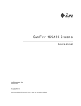
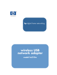
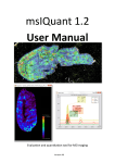
Product Brochure | 02.00 Radiomonitoring & Radiolocation R&S®EB510 HF Monitoring Receiver High-performance radiomonitoring from 9 kHz to 32 MHz R&S®EB510 HF Monitoring Receiver At a glance The R&S®EB510 HF monitoring receiver is designed to meet the demanding requirements of ITUcompliant radiomonitoring tasks in stationary and mobile environments The receiver performs highspeed signal search in the spectrum and provides very wideband demodulation as well as spectrum overview. It can be operated via the front panel or via remote control software. It is the ideal choice for a large variety of applications from single-station measurements to nationwide monitoring systems. The R&S®EB510 HF monitoring receiver has an outstanding feature set for monitoring transmissions, detecting interference, finding unlicensed transmitters or even functioning as a search receiver in the HF spectrum. In addition, it is exceptionally compact and has a low-power design. The R&S®EB510 is the optimum solution for systems that need a high-end receiver but only have limited available space. When combined with analysis software (such as R&S®GX430, for example), it becomes a complete and compact receiving and analysis system covering the frequency range from 9 kHz to 32 MHz. R&S®EB510 with front panel. 2 The receiver can be operated with diverse antennas such as broadband omnidirectional antennas and directional antennas. To limit overloading when using wideband antennas, the R&S®EB510 is equipped with a preselection stage (as recommended by ITU). As a result, intermodulation characteristics are significantly improved. Due to its compact size and excellent balance between performance and power consumption, the R&S®EB510 is designed not just for stationary operation but also for installation in vehicles, in vessels or in aircraft (as payload). Key facts ❙❙ Digital direct conversion receiver from 9 kHz to 32 MHz ❙❙ IF spectrum of up to 32 MHz and parallel demodulation with bandwidths from 100 Hz to 5 MHz ❙❙ Fast panorama scan with up to 60 GHz/s across the entire frequency range ❙❙ High-speed frequency and memory scan with up to 1600 channels/s ❙❙ Polychrome IF spectrum for reliable detection of pulsed signals ❙❙ Spectrum and spectrogram (waterfall) display on receiver (model .03) or on PC via the R&S®EB510-Control software (both model .02 and model .03) ❙❙ AM, FM, I/Q, AM2, FM2, I/Q2 video panorama ❙❙ 1 Gbit LAN interface for remote control and data output ❙❙ Comparatively low power consumption for efficient DC operation, e.g. on a vehicle battery ❙❙ Space-saving system integration due to ½ 19" width and three height units ❙❙ Classification and analysis of signals up to 5 MHz bandwidth (analog and digital modulation) through evaluation of the I/Q data stream using the R&S®GX430IS software (in offline mode) ❙❙ Multichannel digital downconversion (DDC) within realtime bandwidth R&S®EB510 without front panel. R&S®EB510 HF Monitoring Receiver Benefits and key features High receiver sensitivity, high signal resolution ❙❙ State-of-the-art FFT-based digital signal processing for high receiver sensitivity and detection of extremely weak signals without any loss in processing speed ❙❙ Significantly superior signal resolution (compared to conventional analog broadband receivers) Comprehensive spectrum analysis with polychrome display ❙❙ Polychrome display for detection and analysis of shortduration signals ❙❙ Multiple-color spectrum display (polychrome IF spectrum) and color coding of signal duration in the spectrum ❙❙ Distinction of overlapping short-duration signals (displayed in blue) and long-duration signals (displayed in red), e.g. wideband interference resulting from switching power supply leakage Wide spectrum view without scanning ❙❙ Full 32 MHz IF spectrum display without scanning ❙❙ Monitoring of entire HF range in a single spectral view with simultaneous demodulation ❙❙ Panorama scan function for spectral overview with narrower preselection Retrieval of information through demodulation and signal analysis in a compact system ❙❙ Online LAN transfer from an R&S®EB510 to a PC with R&S®GX430 analysis software, for example, for operating an efficient small system for signal reception and analysis ❙❙ Online analysis or recording of captured data using R&S®GX430, provision of data for documentation, replay or subsequent additional evaluation ❙❙ ITU-compliant signal analysis in line with ITU-R SM.1600 using R&S®GX430 and R&S®GX430IS, optimum tool for single-channel analysis and measurement of analog and digitally modulated signals in accordance with ITU requirements Efficient operation via remote control ❙❙ Remote control of all receiver functions via LAN interface (SCPI command set) ❙❙ LAN interface for providing the maximum measured data rate during receiver operation; efficient remote operation in unattended monitoring stations (interface description available, especially essential for system integrators who need to incorporate the receiver into existing software environments) Convenient r emote control with R&S®EB510-Control software ❙❙ Short learning curve due to straightforward menu structure and simple operation ❙❙ Alignment of displayed signals (depending on task), optimum display on screen ❙❙ Remote control of receiver via PC, recording of measured data on hard disk and replay of data on PC for analysis purposes ❙❙ Expansion of remote control software functionality through options and add-ons from the R&S®RAMON software suite ▷▷ page 12 Future-ready investment ❙❙ Wide realtime bandwidth and very high scan speed for fast and reliable detection of all signal types in the HF range ❙❙ Reception, demodulation and processing of signals of current and future radio services in the HF spectrum Wideband pulsed interference caused by a switching power supply. Rohde & Schwarz R&S®EB510 HF Monitoring Receiver 3 R&S®EB510 HF Monitoring Receiver Model overview The design concept of the R&S®EB510 is based on the current R&S®EB500 middle-class receiver. Both receivers feature an HF frontend module similar to that of the R&S®ESMD high-end wideband monitoring receiver. The R&S®EB510 HF monitoring receiver completes the receiver portfolio, addressing users who concentrate only on the HF range. Offering excellent RF performance, high dynamic range and powerful preselection, this receiver provides superior HF reception. When equipped with a front panel, the R&S®EB510 can be directly operated via the frontend GUI and also easily incorporated into a system network. Without front panel, it is ideal for system applications where direct access to the equipment is not necessary. The R&S®EB510 can be fully remote-controlled by using the LAN interface, the remote control software and the open SCPI command set for customized solutions. Overview of Rohde & Schwarz radiomonitoring receivers Realtime IF bandwidth (standard/optional) Demodulation bandwidth ¸ESMD Frequency range: standard/optional Realtime bandwidth Demodulation bandwidth ¸EB500 ¸EB510 ¸EM100 4 26.5 GHz 6 GHz 7.5 GHz 3.5 GHz 3.6 GHz 20 MHz 32 MHz 9 kHz 60 kHz 80 MHz 50 MHz 20 MHz 32 MHz 5 MHz 10 MHz 2 MHz 500 kHz 0 Hz 20 kHz ¸PR100 R&S®EB510 HF Monitoring Receiver Applications Interference d etection and location in professional radio networks ❙❙ Reliable detection of radio interference caused, for example, by defective electronic equipment ❙❙ Fast and effective identification of interference sources, e.g. in ground communications ▷▷ page 6 Monitoring of user-specific radio services ❙❙ Monitoring of a large number of radio services with different scan modes ▷▷ page 7 Multichannel digital downconversion (DDC) ❙❙ Parallel monitoring of one plus three signals ❙❙ All DDC channels user-selectably distributed within realtime bacndwidth ❙❙ Independent demodulation, level measurement and recording of each channel ▷▷ page 8 Nationwide monitoring system for regulatory authorities ❙❙ ITU-compliant spectrum monitoring using the R&S®ARGUS system software ❙❙ Full access to receiver functions from a PC ❙❙ Automatic identification of deviations from the desired state ❙❙ Guided measurements ❙❙ Easy integration into existing R&S®ARGUS radiomonitoring systems ❙❙ Remote operation made easy ❙❙ Nationwide radiomonitoring network at a glance – R&S®ARGUS station information system ▷▷ page 9 Handoff receiver in networked systems ❙❙ Parallel demodulation of multiple narrowband signals and simultaneous broadband spectrum scanning ▷▷ page 11 Rohde & Schwarz R&S®EB510 HF Monitoring Receiver 5 Interference detection and location in professional radio networks Reliable detection of radio interference caused, for example, by defective electronic equipment To master these tasks, the receiver includes special functions such as selectable measurement time and continuous or periodic level output. Since these functions are also effective in the panorama scan spectrum, even nonperiodic interferers can be easily detected. Such interferers are otherwise very difficult to detect due to their irregular appearance in a quickly changing spectrum. Fast and effective identification of interference sources, e.g. in ground communications The simultaneous use of the R&S®GX430 analysis software allows efficient differentiation between wanted signals and possible interference signals. Fast differentiation is especially important in security-critical radio scenarios (e.g. vessel traffic service, VTS) as it prevents high failure costs for the service provider. The combination of a fast panorama scan to acquire an overview of the situation with subsequent scanning and analysis in fixed-frequency mode based on I/Q data is particularly well suited to such applications. In the panorama scan mode, the frequency range of interest is scanned in defined steps, and an FFT of suitable width is calculated for each step. The step width for the fast panorama scan can be selected from 100 Hz to 2 MHz to match the channel spacing used by a wide variety of radio services. The panorama scan provides high scan rates at narrow resolution bandwidths, yielding high sensitivity and signal resolution without compromising the wideband overview. Its high performance and wide range of special functions make the R&S®EB510 an ideal choice for detecting all types of radio interference efficiently. Interference in radiocommunications, e.g. in ground communications, not The R&S®EB510’s panorama scan makes it possible to examine the entire only impedes operation – it may even pose a threat to life. HF frequency band, including preselection filtering and showing results in the combined s pectrum and waterfall display. 6 Monitoring of user-specific radio services Monitoring of a large number of radio services with different scan modes In the frequency scan mode, a user-defined frequency range is scanned using fixed channel spacing. The receiver steps through the frequency range of interest and checks every channel for occupancy. If a signal is detected with a level exceeding the predefined threshold, the receiver dwells at the corresponding frequency for the set hold time, allowing for the signal to be demodulated and processed. In the case of analog modulation, the demodulated signal can be monitored via the headphones or loudspeaker. In the memory scan mode, predefined channels stored in memory locations are consecutively scanned and analyzed to see if any signals are present. The R&S®EB510 offers 10 000 user-definable memory locations. Receive parameters can be assigned separately to each memory location. The memory scan mode is particularly useful for scanning individual frequencies that do not have a fixed channel spacing or that use different demodulation modes and bandwidths. The memory scan mode offers users a greater degree of freedom than the frequency scan mode in similar applications. The frequency scan mode is mainly intended for monitoring radio services that use fixed channel spacing, whereas the memory scan mode is used for variable channel spacing. Smooth operation of an organization’s own radio network is vital to ensure operational readiness — not only for government operators. Rohde & Schwarz R&S®EB510 HF Monitoring Receiver 7 Multichannel digital downconversion (DDC) Parallel monitoring of one plus three signals within realtime bacndwidth When equipped with the R&S®EB510-DDC digital downconverter option, the receiver has three additional digital downconverters in addition to the wideband demodulation path. These converters function entirely in parallel within the realtime bandwidth and can be parameterized independently of one another. Each of these digital downconverters features: ❙❙ AM, FM, PULSE, I/Q, LSB, USB and CW demodulation mode ❙❙ Comprehensive set of 20 IF bandwidths from 100 Hz to 150 kHz (100 Hz to 9 kHz for LSB, USB, CW) ❙❙ Squelch function Moreover, each DDC with individual AGC provides the complex baseband (I/Q), the associated signal level and an audio signal. The data streams output at the DDC channels can be either recorded internally in the receiver, or are available via LAN to be recorded by the remote control PC. Recording of four independent data streams is supported by the R&S®EB510-Control software package. Smooth one plus three demodulation channels can be user-distributed within the realtime bandwidth. Control interface for managing of DDC information output. 8 Nationwide monitoring system for regulatory authorities ITU-compliant spectrum monitoring using the R&S®ARGUS system software For more than 20 years, R&S®ARGUS has been a highly successful control software solution for ITU-compliant measurement and analysis tasks. It offers a variety of measuring modes designed to support typical measurement procedures and greatly simplify everyday tasks. It can also perform a large number of analyses that enable detailed evaluation of measurements and the creation of precise, in-depth reports. These capabilities are now also available in combination with the R&S®EB510. Full access to receiver functions from a PC The user-friendly standard interface in R&S®ARGUS makes the entire range of R&S®EB510 functionality available on a PC. Measurement results are displayed in realtime in the form of graphics and tables. The results are stored along with the receiver settings in an internal database to allow subsequent evaluation in line with ITU requirements. The entire system is calibrated, taking into account the frequency-dependent sensitivity of the antenna and attenuation and loss in cables and switches. Automatic identification of deviations from the desired state In combination with R&S®ARGUS, the R&S®EB510 can automatically identify whether the current signal scenario is consistent with expectations. Users can define a valid range of values for each measurement parameter depending on the frequency. If a measured value is outside the defined range, R&S®ARGUS immediately issues an alarm. As a result, new and unknown transmitters can be discovered just as easily as transmitters that exceed licensed transmission parameters (e.g. excessive frequency deviation). Guided measurements One unique feature in R&S®ARGUS are its guided measurement modes. Users simply choose a frequency range and the type of measurement task (field strength, spectrum occupancy or bandwidth, for example). R&S®ARGUS then configures the right device settings automatically and selects the appropriate antenna based on the frequency and polarization. This allows even relatively inexperienced users to conduct complex measurements with the R&S®EB510. Rohde & Schwarz R&S®EB510 HF Monitoring Receiver 9 Easy integration into existing R&S®ARGUS radiomonitoring systems The R&S®EB510 is quick and easy to integrate into existing infrastructures as a replacement for existing equipment or to expand a station’s measurement capabilities. Importantly, the receiver can operate not just in combination and coordination with other equipment such as direction finders and specialized analysis devices but also as a handoff receiver in a networked system. The ability to operate in parallel is not confined to the devices within a single radiomonitoring station: Multiple devices at separate stations can process several measurement tasks synchronously. Remote operation made easy Remote operability is a key requirement for radiomonitoring systems, and here, too, R&S®ARGUS sets standards. It has built-in sophisticated bandwidth management (SBM) that tunes the transmission rate to suit the available network bandwidth. If necessary, the software can reduce and compress data automatically. This ensures, for example, that the receiver’s IF spectrum and audio streams reach the central station in sufficiently high quality, even with narrowband connections. Nationwide radiomonitoring network at a glance – R&S®ARGUS station information system Station information system (SIS) display UMS100-99992 River police Headquarters at Munich airport (Germany) An example map showing a number of monitoring stations and their current status (indicated by different colors). 10 Another advanced feature of R&S®ARGUS is its station information system (SIS). The SIS shows the current status of every radiomonitoring system location on an electronic map. The information provided includes the current connection status, the availability and utilization of measuring equipment, ambient parameters such as temperature and humidity, as well as the power supply status in unattended radiomonitoring stations. The map display also supports remote control features. When users click a symbol on the map, R&S®ARGUS automatically connects to the receiver in question. The R&S®EB510 in the remote station is then ready to accept measurement tasks. Handoff receiver in networked systems Parallel demodulation of multiple narrowband signals and simultaneous broadband spectrum scanning Multiple R&S®EB510 receivers can be combined and operated as a bundled solution. One R&S®EB510 is used as a search receiver, the others are used for demodulating signals and producing audio or I/Q data streams. The handover of a signal from the search receiver to a data production receiver is carried out from the user workstation running with R&S®RAMON system software. The major advantage of this system configuration is that the fast signal search across a wide frequency scenario and the narrowband production of multiple audio or I/Q data streams occur simultaneously. This allows the user to achieve optimum results in a minimum of time. Multiple ¸EB510 receivers can be operated together via ¸RAMON system software ••• Search receivers Data production receivers ¸RAMON system software Display of IF spectrum and use of marker function. Rohde & Schwarz R&S®EB510 HF Monitoring Receiver 11 Convenient remote control with R&S®EB510-Control software Major functional features of R&S®EB510-Control Fast and simple operation The main functions can be accessed using shortcuts. The graphical display of results includes: ❙❙ IF spectrum with waterfall diagram ❙❙ Panorama scan spectrum with waterfall diagram ❙❙ Level indication based on demodulation path Users can adapt the colors of the display and the size and arrangement of the windows as required for a specific task or area of application. Easy-to-use measurement functions are available within the diagrams. Wideband panorama scan with Max Hold function and waterfall diagram. 12 Display, storage and playback of spectra and waterfall data R&S®EB510-Control enables the recording and playback of panorama scan and IF signal spectra. In addition, digital audio data and I/Q baseband data (digital IF) of up to 5 MHz bandwidth can be stored, e.g. for the subsequent analysis of digitally modulated signals. Buffering of frequency scan data in a ring buffer Recording in the ring buffer can be stopped by a mouse click. The stored signals are then available in playback mode for analysis. Frequency list for marking signals With a mouse click, radio channels can be marked, saved in a list and graphically placed over the spectrum. The frequency list is available for storage and subsequent analysis. The R&S®EB510-Control remote control software is supplied free of charge with the R&S®EB510. It is part of the R&S®RAMON software family and e nables convenient and efficient operation of the receiver from a PC workstation. The software o ffers a straightforward menu structure and intuitive operation so that training requirements for operating personnel are minimal. Operating principle Frontend Signals are fed in via three separate antenna sockets. Each of these three sockets can be used for HF signals from 9 kHz to 32 MHz. Signals from 9 kHz to 32 MHz are routed directly to the A/D converter via an HF preselection block consisting of tunable bandpass filters and a 32 MHz lowpass filter. The preselection effectively protects the A/D converter against overloading due to the presence of strong signals outside the frequency range of interest. Digital signal processing After A/D conversion of the signal (with a 16 bit converter), the signal path is split up: In the first path, the IF spectrum is calculated using a digital downconverter (DDC), a digital filter and an FFT block. The bandwidth of the bandpass filter can be selected between 1 kHz and 32 MHz. Before the IF spectrum is output via the LAN interface or on the display, results are postprocessed using the average, min. hold or max. hold function as selected by the user. In the second path, which also includes a DDC and digital filters, the signal is processed for level measurement or demodulation. To process the different signals with optimum signal-to-noise ratio, the receiver contains IF filters with demodulation bandwidths from 100 Hz to 5 MHz, which can be selected independently of the spectral IF bandwidth. Prior to the level measurement, the absolute value of the level is determined and weighted using the average, peak, RMS or fast (sample) function, as selected by the user. The measured level is then output on the display or via the LAN interface. To demodulate analog modulated signals, the complex baseband data passes through AM, FM, USB, LSB, ISB, pulse or CW demodulation stages after the bandpass filter and is subjected to automatic gain control (AGC) or manual gain control (MGC). After the AGC/MGC stage, the complex baseband data (I/Q data) resulting from the digitally modulated signals is directly output for further processing. Block diagram of frontend HF input 9 kHz to 32 MHz HF preselection filter bank Lowpass filter 32 MHz to HF A/D converter Rohde & Schwarz R&S®EB510 HF Monitoring Receiver 13 The results obtained are available as digital data and can be output via the LAN interface as required for the particular task. Digital audio data is reconverted to analog signals for output via the headphone socket or loudspeaker. Analog signals are reconverted from the I/Q data by a 16 bit D/A converter; they are then available as analog IF signals or analog video data. High receiver sensitivity, high signal resolution The R&S®EB510 features an IF bandwidth of up to 32 MHz. This allows even very short signal pulses to be captured since the receiver displays the wide bandwidth of 32 MHz in a single spectrum around the set center frequency without any scanning being required. Using the AUTO setting, the widest IF bandwidth of 32 MHz yields the widest spectral display; the narrowest IF bandwidth of 1 kHz yields maximum sensitivity and resolution. Block diagram of digital signal processing Clear/write IF panorama path DDC IF spectrum 1 kHz to 32 MHz FFT 4096 points 16 bit Display and LAN IF spectrum Min. hold Max. hold A HF direct Average D Fast Demodulation path DDC ABS value Demodulation bandwidths 100 Hz to 5 MHz Display and LAN Level measurement Average ITU measurement RMS Peak Video spectrum Lowpass filter A Video/IF analog output 14 D 16 bit Digital upconverter Analog audio AGC Digital audio via LAN MGC I/Q data via LAN Demod The receiver’s IF spectrum is digitally calculated using Fast Fourier Transform (FFT). The use of FFT computation at the IF offers a major advantage: The receiver sensitivity and signal resolution are clearly superior to those of a conventional analog receiver at the same spectral display width. IF spectrum FFT calculation of the IF spectrum is performed in a number of steps. These are described below in simplified form for an exemplary IF bandwidth of 20 MHz (BWIF spectrum = 20 MHz), which yields a wide spectral display. Due to the finite edge steepness of the IF filter, the sampling rate fS must be larger than the selected IF bandwidth BWIF spectrum. The quotient of the sampling rate and the IF bandwidth is a value > 1 and is a measure of the edge steepness of the IF filter. This relationship is expressed by the following two formulas (for the AUTO s etting): fs BWIF spectrum = const or fS = BWIF spectrum × const The value of the constant is dependent on the selected IF bandwidth, i.e. it may vary as a function of the IF bandwidth. For an IF bandwidth of BWIF spectrum = 20 MHz, the constant has a value of 1.28. Therefore, to display a 20 MHz IF spectrum, a sampling rate of fS = 25.6 MHz is required. The R&S®EB510 uses a maximum FFT length N of 4096 points to generate the IF spectrum. To calculate these points, the 25.6 MHz sampling band in the above example is divided into 4096 equidistant frequency slices, which are also referred to as bins (see figure “Signal p rocessing for IF spectrum”). The bandwidth BWBin of the frequency slices is obtained as follows: BWBin = Signal processing for IF spectrum fs 4096 = 25.6 MHz 4096 = 6.25 kHz a in dBµV n=1 n = 4096 fRX 20 MHz Frequency in MHz 25.6 MHz Actual sampling bandwidth compared with selected IF bandwidth. Rohde & Schwarz R&S®EB510 HF Monitoring Receiver 15 This means that in the above example only the calculated bandwidth of 6.25 kHz for each bin has to be taken into account as the noise bandwidth in the calculation of the displayed noise level (DNL) in accordance with the formula below (the effect of the window function (Blackman window) of the FFT is not considered here for simplicity’s sake): DNL = –174 dBm + NF + 10 × log(BWBin/Hz) The quantity NF represents the overall noise figure of the receiver. The above example shows that, due to the use of the FFT, the actual resolution bandwidth (RBW) to be taken into account in DNL calculation is clearly smaller (i.e. BWBin) than would be expected for the wide (unscanned) display range of 20 MHz. Another advantage of the high spectral resolution used in the FFT calculation is that signals located close together (e.g. f1, f2 and f3) can be captured and represented in the IF spectrum as discrete signals (see figure “Signal display in IF spectrum”). If, on an analog receiver, a resolution bandwidth equal to the set IF bandwidth were selected (RBW = BWIF spectrum), a sum signal fSum would be displayed instead of the three discrete signals f1, f2 and f3. The realtime signal processing at the IF level also includes other high-performance capabilities, such as overlapping FFT for the optimum capture of pulsed signals and a configurable bin width for adjusting to the channel spacing of known radio services. These functions are described in detail in the user manual. Signal display in IF spectrum IF spectrum a IF bandwidth f1 a f2 f3 f Input signal f1 IF spectrum f2 f3 f a IF bandwidth f1 f2 f3 f Signal resolution in IF spectrum in digital and analog receiver concept. 16 Digital Input signal fsum f Analog a Panorama scan The receiver’s maximum FFT bandwidth of 32 MHz makes it possible to perform extremely fast scans with the panorama scan. As is done for the IF spectrum, an FFT is used to process the broad window with the possibility of selecting a finer resolution. The width of the frequency window and the FFT length (number of FFT points) are variable and are selected by the receiver. In the panorama scan mode, the user can select among 24 resolution bandwidths from 100 Hz to 2 MHz. The resolution bandwidth corresponds to the width of the frequency slices (bin width) mentioned under “IF spectrum”. Based on the selected bin width and start and stop frequency, the R&S®EB510 automatically determines the required FFT length and the width of the frequency w indow for each scan step. The receiver selects these internal parameters so that the optimum scan speed is achieved for each resolution bandwidth (see figure “Resolution in p anorama scan mode”). In the panorama scan mode, the resolution bandwidth of 2 MHz yields the maximum scan speed, while the resolution bandwidth of 100 Hz yields maximum sensitivity. The resolution bandwidth (bin width) for the panorama scan (selectable between 100 Hz and 2 MHz) therefore corresponds to the resolution bandwidth (BWBin) used in the DNL calculation for the IF spectrum (see DNL formula under “IF spectrum”), and can be used for calculating the DNL for the panorama scan. Moreover, the user selects the resolution bandwidth to obtain the desired frequency resolution (see figure “Bin width and channel spacing”). The above explanations show that the use of digital signal processing in a radiomonitoring receiver offers decisive advantages. Extremely high sensitivity (due to very fine resolution) combined with a broad spectral overview and maximum scan speed significantly increases the probability of intercept in comparison with an analog receiver. a in dBµV Signal processing in panorama scan mode max. 32 MHz FFT window 1 n=1 FFT window n FFT window 2 n=X fstart fstop Frequency in MHz Basic sequence of steps in fast panorama scan mode. Resolution in panorama scan mode Bin width and channel spacing a in dBµV a in dBµV Points for FFT calculation max. 32 MHz n=1 n=X Bin width Channel spacing Frequency in MHz Bin width: f1 min. 100 Hz max. 2 MHz Selecting the panorama scan resolution by varying the bin width. f2 Frequency in MHz Signal frequencies Selecting a 12.5 kHz bin width to capture a radio service using 12.5 kHz channel spacing. Rohde & Schwarz R&S®EB510 HF Monitoring Receiver 17 Specifications in brief Specifications in brief Frequency Frequency range base unit 9 kHz to 32 MHz all IF bandwidths AM, FM, φM, PULSE, I/Q IF bandwidths ≤ 9 kHz LSB, USB, CW IF bandwidths ≥ 1 kHz ISB demodulation, level and offset measurements (3 dB bandwidth), 29 filters 100/150/300/600 Hz, 1/1.5/2.1/2.4/2.7/3.1/4/4.8/6/9/12/15/30/50/ 120/150/250/300/500/800 kHz, 1/1.25/1.5/2/5 MHz up to 4096-point FFT dynamic, overlapping FFT operating modes automatic or variable with selectable frequency resolution 0.625/1.25/2.5/3.125/6.25/12.5/25/31.25/50/62.5/ 100/125/200/250/312.5/500/625 Hz, 1/1.25/2/2.5/3.125/5/6.25/8.333/10/12.5/20/ 25/50/100/200/500 kHz, 1 MHz, 2 MHz 1/2/5/10/20/50/100/200/500 kHz, 1/2/5/10/20/32 MHz clear/write, average, max. hold, min. hold, histogram 10 000 programmable memory locations speed up to 1600 channels/s speed user-selectable start/stop frequency and step width up to 1600 channels/s Demodulation Demodulation modes IF bandwidths Bandwidth IF panorama FFT IF panorama IF panorama span Panorama display Memory scan Frequency scan Panorama scan with R&S®EB510-PS option speed For data sheet, see PD 5214.5210.22 and www.rohde-schwarz.com 18 RF spectrum with user-selectable start/stop frequency and step width: 100/125/200/250/500/625 Hz, 1/1.25/2/2.5/3.125/5/6.25/8.333/10/12.5/20/ 25/50/100/200/500 kHz, 1 MHz, 2 MHz up to 60 GHz/s Ordering information Designation Type, description Order No. HF Monitoring Receiver, with control front panel R&S®EB510 4091.7009.03 HF Monitoring Receiver, without control front panel frequency range from 9 kHz to 32 MHz, IF spectrum (max. 32 MHz), remote control software supplied with receiver R&S®EB510 4091.7009.02 frequency range from 9 kHz to 32 MHz, IF spectrum (max. 32 MHz), remote control software supplied with receiver Software options Digital Downconverter R&S®EB510-DDC 4072.9500.04 Panorama Scan three digital downconverter for user-defined placement within realtime bandwidth R&S®EB510-PS 4072.9200.04 ITU Measurement RF scan, high-speed FFT scan across user-selectable range, selectable spectral resolution R&S®EB510-IM 4072.9100.04 Selective Call ITU-compliant measurement of AM/FM-modulated signals in the R&S®EB510 R&S®EB510-SL 4072.9800.04 selective call analysis Software Package in line with ITU-R SM.1600 (for R&S®GX430IS ITU-compliant measurement of signals with analog or digital modulation) Accessories 4071.5817.02 19" Rack Adapter R&S®ZZA-T04 1109.4187.00 19" Rack Adapter for mounting two R&S®EB510 in a 19" rack (both receivers side by side) R&S®ZZA-T02 1109.4164.00 for mounting one R&S®EB510 in a 19" rack (including one blind plate) DC Power Cable R&S®EB500-DCC 4072.7036.00 R&S®EB510-DCV 4072.8403.04 Calibration documenting Documentation of Calibration Values Service options Extended Warranty, one year R&S®WE1EB510 Extended Warranty, two years R&S®WE2EB510 Extended Warranty, three years R&S®WE3EB510 Extended Warranty, four years R&S®WE4EB510 Extended Warranty with Calibration Coverage, one year R&S®CW1EB510 Extended Warranty with Calibration Coverage, two years R&S®CW2EB510 Extended Warranty with Calibration Coverage, three years R&S®CW3EB510 Extended Warranty with Calibration Coverage, four years R&S®CW4EB510 Please contact your local Rohde & Schwarz sales office. Your local Rohde & Schwarz expert will help you determine the optimum solution for your requirements. To find your nearest Rohde & Schwarz representative, visit www.sales.rohde-schwarz.com Rohde & Schwarz R&S®EB510 HF Monitoring Receiver 19 Service you can rely on ❙ ❙ ❙ ❙ ❙ Worldwide Local and personalized Customized and flexible Uncompromising quality Long-term dependability About Rohde & Schwarz Rohde & Schwarz is an independent group of companies specializing in electronics. It is a leading supplier of solutions in the fields of test and measurement, broadcasting, radiomonitoring and radiolocation, as well as secure communications. Established more than 75 years ago, Rohde & Schwarz has a global presence and a dedicated service network in over 70 countries. Company headquarters are in Munich, Germany. Environmental commitment ❙❙ Energy-efficient products ❙❙ Continuous improvement in environmental sustainability Certified Quality System ISO 9001 Rohde & Schwarz GmbH & Co. KG www.rohde-schwarz.com Regional contact ❙❙ Europe, Africa, Middle East | +49 89 4129 12345 [email protected] ❙❙ North America | 1 888 TEST RSA (1 888 837 87 72) [email protected] ❙❙ Latin America | +1 410 910 79 88 [email protected] ❙❙ Asia/Pacific | +65 65 13 04 88 [email protected] ❙❙ China | +86 800 810 8228/+86 400 650 5896 [email protected] R&S® is a registered trademark of Rohde & Schwarz GmbH & Co. KG Trade names are trademarks of the owners | Printed in Germany (sk) PD 5214.5210.12 | Version 02.00 | August 2012 | R&S®EB510 Data without tolerance limits is not binding | Subject to change © 2011 - 2012 Rohde & Schwarz GmbH & Co. KG | 81671 München, Germany 5214521012