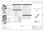
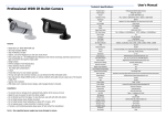
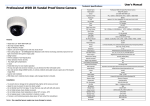
1
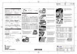
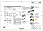
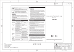
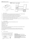
05
06
07
Connect modules in cascade, join
the red stripe wires together and
white wires together with wire
connectors, and treat them with
waterproofing and anti-corrosion.
Notes: Please ensure the maximum
cascade quantity is less than or
equal to 30pcs when only one end
of the module string is powered.
Adjust the modules to the best
position according to the effect
of lighting distribution. Then,
press the adhesive tape tightly
and fix modules well with
screws.
Drill a hole in an appropriate
position with an electrical drill,
run the cable of power supply
through the hole and fix and
protect the cable well.
Notes: Drill a hole with a proper
force to avoid the panel of the light
box is broken due to the big force.
08
Make sure the red stripe wire(+)
and the white wire (-) of the
modules connected to the
output of the power supply
rightly, and treat them with
waterproofing and
anti-corrosion.
NOTES
1. Installation notes:
(1)Make sure the red stripe wire (+) and white wire (-) of the
modules connected to the output of the power supply rightly;
otherwise, the product can not work.
(2)Drive the screws properly, too much or too small driving
force will cause the installed hole deformed or cracked or
modules tilting or loose fastening.
(3)Connect wires to connectors solidly. It will be fine if the
connectors can not be pull out easily by hand.
2. Notes for other installation materials used :
(1)The wire connectors must be treated well for waterproofing
and anti-corrosion.
(2)The self-tapping screws should be selected appropriately
based on the thickness and materials of the installation
board.
备注 :
1.尺 寸:38 5* 21 0m m;
2.材 质:60 G书 纸;
3.公 差:±1 mm;
4.灰 度双 面 印刷 ;
5.虚 线不 印 刷, 来料 必 须从 虚线 处折好 。
6.对 应旧 编 码:552 4- 08 90 00 -0 1。
(3)Modules maximum cascade number is 30pcs per string when
only one end of the string is powered. Please choose safety
certified Switch Mode power supply with DC12V output
voltage and 30W rated power (with short-circuit, overvoltage
and overloading protections and with maximum ±5%
undulating voltage output) for ONE module string. If more
modules are used, please make sure the power supply have
15% output surplus over its real load.
Malfunction&Solutions Table
Malfunction & Solutions Tables
Malfunctions
Possible Causes
1, No electricity supplied.
None LED
works
2, The power supply is auto
protected caused by the
power supply output short or Remove any short-circuiting
open circuit.
malfunctions, re-electrify
3, The input positive & negative the wires rightly.
wires of the modules are
connected reversely.
1, No output from part of power
supply.
Part of the
LEDs don't
work
Solutions
Power on the supply power.
2, Part of modules connected
wrongly to the power supply.
Connect the wires rightly.
1, The power supply is over
loaded.
Use bigger or more power
supplies.
3, Too more LED modules
cascaded.
LEDs blinking 1 , Intermittent connections.
2,Failures of the power supplies.
Venus Series LED Modules
User Guide
M601FB
Declaration
Check the power supply and
remove malfunctions.
3,Some modules' polarities
connected reversely.
Non-uniform 2, The voltage loss of the power
supply is too big.
or not enough
LED brightness
During installing, please insulate all the exposed wires,
meanwhile, treat them with waterproofing and anti-corrosion.
Please choose 18AWG wires or thicker wires to use to avoid
overload causing over-heat or other unwanted consequences.
Before power on, please check whether the voltage is under rated
voltage and the circuit is connected rightly.
This products is applicable ONLY to the inside of the light boxes
or channel letters, prohibited to be exposed in the outdoors
directly!
The products should be installed or maintained ONLY by the
professional persons.
The maximum available cascade of LED modules is 30pcs per
string when only one end of the string is powered. Forbid
exceeding.
Generally the length of main cable cannot exceed 2m between
power supply and module strings especially maximum 30pcs per
string is applied. Otherwise, the voltage losing will increase,
which will cause the inconsistent brightness between the two
ends of module strings.
Ensure modules voltage with
12V±5%, shorten the power
supply wire or use thicker wires or
balance the wires distances to
keep voltage loss in a balance.
Adjust each module cascade
quantity to meet each electric
current loop maximum load.
Warranty: 3 years or 13,000 hours, whichever comes first.
If the external flexible cord of this luminaire is damaged, it shall
be exclusively replaced by the manufacturer or his service agent
or a similar qualified person in order to avoid a hazard.
The given data in this manual is based on our standard product.
The actually delivered products may vary. Please be subject to
actual product data.
All the product diagrams and pictures are schematic plots in this
manual. Please quote according to the received goods.
Modifications or revisions or innovations are not subject to prior
notice.
Find the intermittent connections
and remove any malfunctions.
Replace the power supplies.
WARNING
Do not disassemble or modify the module; Don't touch LED
surface with sharp tools.
Don't install the modules during power on.
Prohibited to use any organic chemical solvents.
Forbid using any acid and alkali adhesive or glue to install the
product. Please use neutral glass glue to fix the product, and
cannot seal the light box or channel letter until the glue is
solidified in the opening environment for 4 hours.
Read this manual carefully before using this product and keep it!
V1.0
说明书正面
60G书 纸
启明星H
方艳平
灰度印刷
2 01 2.0 2. 08
M601FB
308 - 01 - 054
共 2 页
产品说明书(中性 英文)
1:1
第 1 页
WI-RD-8-11-112
V0
Installation & Application Examples
Model no. and Specification
04
1. Layout for Light box
Model:
M601FB
Rated Power (W/piece):
0.7
Reference Scheme (White Lighting)
Working Voltage (V):
DC12
IP Grade :
IP66
Light Box
Thickness(mm)
Space between
Modules(mm)
Installation Density
(pcs/m²)
Illumination
Scope(lux)
Operation Temperature (℃):
-25~60
dz=100
dx=90 dy=60
185
5000 - 6200
dz=120
dx=110 dy=80
114
3300 - 4200
dz=140
dx=130 dy=100
77
2900 - 3300
dz=160
dx=150 dy=120
56
2100 - 2400
dz=180
dx=170 dy=140
42
1700 - 1900
dz=200
dx=190 dy=160
33
1400 - 1600
dz=220
dx=210 dy=180
26
1200 - 1400
Storage Temperature (℃):
-40~70
Profile
Standard Cascade Dimension
Unit: mm
Notes: Cutting position should be at the
middle of the wire.
05
06
Install Procedures
Parts and Tools
01
Cap exposed wires of the last
module with two wire connectors,
and seal with resin for
waterproofing and anti-corrosion.
2.Layout of the Channel Letters
Reference Scheme (White Lighting)
Channel Letters
Strokes
Width
Thickness
Dimension
Modules
07
Clean the installation surface.
1. Installation and Connection Illustration:
Max. cascade of modules=30pcs
Power Appearance (Only for reference)
Connect modules in cascade, join
the red stripe wires together and
white wires together with wire
connectors, and treat them for
waterproofing and anti-corrosion.
Notes: Please ensure the maximum
cascade quantity is less than or
equal to 30pcs when only one end
of the module string is powered.
Adjust the modules to the best
positions according to the
effect of lighting distribution.
Then, press the adhesive tape
tightly and fix modules well
with screws.
Installation
Density
Square Maximum Space Overall
Meter between Modules Quantity
(mm)
(
(mm)
(mm)
(m² )
A90
H80
L710*W430
0.3
A110
A140
H100
H120
A150
A170
Illumination
Scope
(pcs/m² )
(lux)
100
20
67
4300-5300
L855*W525 0.45
L1040*W653 0.68
120
150
19
22
42
32
2500-3500
1900-2400
H150
L1194*W710 0.85
180
20
24
1800-2200
H180
L1490*W900 1.34
200
22
16
1300-1600
(mm)
(pcs)
Remark:
1. Tested in 3mm thick white acrylic board with 54.4%
light transmitting rate.
2. All illumination data in the table are the minimum with
uniform acrylic surface illumination.
3. The above data are only for reference.
Remark:
1. Tested in 3mm thick white acrylic board with 54.4%
light transmitting rate.
2. All illumination data in the table are the minimum with
uniform acrylic surface illumination.
3. The above data are only for reference.
Single Module Dimension
Cut off the excessive module(s)
after modules layout, then strip
10mm length of the cutting wires.
Install Procedures
L
H
01
A
W
Clean the installation surface.
Peel off backing to expose
adhesive tape of modules and
stick modules on the installation
surface for preliminary mounting.
02
Red stripe wire (+)
White wire (-)
08
02
Mark the layout guidelines so that
the modules can be spaced
evenly in light box.
Wire is connected to the
output of power supply
Drill a hole in an appropriate
position with an electrical drill,
run the cable of power supply
through the hole and fix and
protect the cable well.
Cut off the excessive module(s)
after modules layout, then strip
10mm length of the cutting wires.
03
Notes: Cutting position should be at the
middle of the wire.
Notes: Drill a hole with a proper
force to avoid the panel of the light
box is broken due to the big force.
2. Product parts and Self-provided tools:
(1) Product Parts
09
03
M601FB(30PCS)
Wire connectors (6PCS)
Cutting Nipper, Electrical
Drill&Drilling Bit
Self –tapping Screw
(ST2.9)
(2) Self-provided tools
备注 :
1.尺 寸:38 5* 21 0m m;
2.材 质:60 G书 纸;
3.公 差:±1 mm;
4.灰 度双 面 印刷 ;
5.虚 线不 印 刷, 来料 必 须从 虚线 处折好 。
6.对 应旧 编 码:552 4- 08 90 00 -0 1。
Peel off backing to expose
adhesive tape of modules and
stick modules on the installation
surface for preliminary mounting.
Make sure red stripe wire (+)
and white wire (-) of modules
strings connected to the output
of the power supply rightly, and
treat them with waterproofing
and anti-corrosion.
Cap exposed wires of the last
module(s) with two wire
connectors, and seal with resin for
waterproofing and anti-corrosion.
04
说明书背面
60G书 纸
启明星H
方艳平
灰度印刷
2 01 2.0 2. 08
M601FB
308 - 01 - 054
共 2 页
产品说明书(中性 英文)
1:1
第 2 页
WI-RD-8-11-112
V0