1
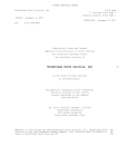
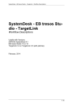
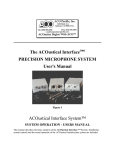
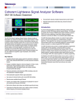
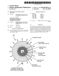
rCube2: Advanced Rapid Prototyping
Electronic Control Unit
OVERVIEW
The rCube2 embedded processing unit is a modular
rapid prototyping system intended for control strategy
development
in
an
automotive
environment.
VARIANT I
Applications are developed in MATLAB® / Simulink®
environment and integrated into the AUTOSAR
(AUTomotive Open System ARchitecture) compliant
VARIANT II
base software. Ricardo provides the base software
and all necessary device drivers.
VARIANT III
KEY FEATURES
rCube2 features a powerful base Input/Output function with additional application I/O modules available to
suit the target application. rCube2 is packaged in a cast aluminium enclosure and sealed for use in the
most demanding automotive environments.
• Dual application processor platform
• Robust packaging designed for in-vehicle use
• Modular expandable I/O system
• Dual voltage 12/24 V systems
• Real-time control with parallel computing core
• Advanced system monitoring and protection
BASE SYSTEM
The rCube2 base system (Variant I in
the
picture
above)
contains
applications
the
processors,
communications
interfaces
(Ethernet,
CAN, FlexRay, LIN & RS232). In
addition to this a range of general
purpose input output functionality is
supported. The system is protected by
an Advanced Monitoring Unit (AMU)
which provides thermal and under/over
voltage
manages
protection.
The
application
AMU
also
wake-up
and
shutdown. CAN based, time based and
periodic wake-up events are supported.
rCube2 Advanced Rapid Prototyping System
th
Revision: 0.28 Date: 23 November 2012
Page 2
BASE EMBEDDED PROCESSING UNIT I/O SUMMARY
The following table summarises the input, output and communications capability of the rCube2 base unit:
Processor 1
Processor 2
Shared resources
CAN
4
CAN
4
Analog inputs (general)
18
FlexRay
2
FlexRay
2
Analog inputs (thermistor)
8
Ethernet
1
Ethernet
1
Digital inputs
(8 can be set to outputs)
16
rCube2 interlink
2
rCube2 interlink
2
Low side power outputs (2 A)
4
LIN
1
LIN
1
Relay power outputs (≤ 250 mA)
8
RS232
1
RS232
1
CORE PROCESSING SYSTEM
The applications core is based on two Infineon TC1797 processors. The processors are arranged in a
symmetrical configuration and as such, applications can run on either one of the processors or split across
both processors.
Performance
Memory (per processor)
Volatile
Non-volatile
Processors (internal)
150 MHz clock
192 kB
4 MB
External (on-board)
75 MHz bus
4 MB
4 MB
The rCube2 embedded processing unit incorporates facility to install an ETAS interface board for each of
the application processors and retain the system’s environmental integrity through installation of connectors
on the top side of the enclosure. This optional unit allows advanced access to the micro-controller
resources for calibration and run-time monitoring if desired by the user.
SYSTEM MODULARITY
The base unit is expandable with one or two
application
specific
input/output
modules
(featured in separate datasheets). Ricardo
supplies input/output application modules to
cover a range of system applications.
•
6 cylinder gasoline and ethanol injected
engines
•
8 cylinder GDI and DI systems
•
AMT and AT transmission systems
•
30 kW 3-phase inverter module (planned)
•
Custom developed modules
rCube2 Advanced Rapid Prototyping System
th
Revision: 0.28 Date: 23 November 2012
Page 3
DEVELOPMENT ENVIRONMENT & TOOLS
The validated system is based on use of the
Tasking Compiler for compilation and build of the
downloadable files for each processor. User
applications
are
developed
as
Control Algorithm
Modelling in
Simulink/Stateflow
software
components using MATLAB/Simulink with Real-
Build
Config File
Time Workshop® Embedded Coder. Ricardo
supplied
tools
manage
the
build
process
generating the download files and the ASAP2 file
A2l File
System
Configuration
in Tresos
Executable
Download
for calibration tools. PCAN USB to CAN interface
(not supplied) from Peak Systems GmbH is
Calibration Tool
Run
XCP
required for data download to the system.
EMBEDDED OPERATING SYSTEM
rCube2 uses a real-time embedded operating system with micro-controller abstraction layer components
supplemented by complex device drivers to support custom functionality such a high speed
communications and engine control. The platform is AUTOSAR compliant making all interaction between
the platform software and the application
software via the RunTime Environment
(RTE) component. This allows the user to
develop
portable
software
readily
transferable to a production system.
The user has access to an operating
system configuration utility to perform the
necessary
low-level
application
configuration. Ricardo can develop preconfigured
applications
concentrate
development.
systems
leaving
on
the
to
the
suit
user
application
user
to
level
rCube2 Advanced Rapid Prototyping System
th
Revision: 0.28 Date: 23 November 2012
Page 4
ELECTRICAL INTERFACE / INPUT-OUTPUT SET
Power supply specifications
Supply voltage
6.0 V to 40 V
Compliant with 24 V systems to ISO7637 part 2
Reverse battery protection
built in
Shutdown current
< 2 mA
System inactive
Standby current
< 5 mA
Periodic wake-up events programmed
Operating current
< 500 mA
Peripheral I/O inactive, application processors active
The rCube2 embedded processor unit without additional modules supports the following signal interfaces:
Low power signal specifications
Analogue inputs
18
14-bit resolution, ~15 kHz bandwidth, 100 kHz sampling rate, 0-5 V input
range, 25 kΩ input impedance, short circuit protected
Analogue inputs
NTC thermistors
8
12-bit resolution, slow scanning (~1 Hz), short circuit protected,
programmable pull-up resistance (4.7 kΩ/334.7 kΩ)
Sensor supply
2
Independent 5 V, 250 mA each, short circuit protected
Digital inputs/outputs
8
Input: Configurable pull-up/down (18 kΩ/ > 100 kΩ in groups of 4), interrupt
capable, short circuit protected, switching threshold: VLOWMAX = 2.57 V,
VHIGHMIN = 3.37 V
Output: Battery level, 200 mA current limited with configurable HS/LS/pushpull drive in groups of 4, with freewheeling diodes & short circuit protection
OR
8
Digital inputs
8
*
*
Configurable pull-up/down (18 kΩ/ > 100 kΩ in groups of 4), interrupt
capable, short circuit protected, switching threshold: VLOWMAX = 2.57 V,
VHIGHMIN = 3.37 V; hardware assisted detection of duty cycle of PWM and
frequency
Power output specifications
Low side drive outputs
4
2 A per channel, PWM capable, over-current and short circuit protection,
common external pin freewheel diodes, internal diagnostics and feedback
Relay drive outputs
4
250 mA low side drives, diagnostics feedback & short circuit protected, relay
1 driven by processor 1, relay 2 driven by processor 2, relay 3 driven by
processors 1 AND 2, relay 4 driven by processor 1 OR 2
Diagnostic LED outputs
4
Power supply, system monitor, processor 1 and processor 2 indication, highside current-limited 20 mA output drive with short circuit protection.
CAN interface
8
4 dedicated to each application processor core – 2/4 with integrated
termination network, CAN 2.0B, capable of generating system wake-up
FlexRay Interface
4
2 dedicated to each application processor core – all with integrated
termination network, capable of generating system wake-up
LIN interface
2
1 dedicated to each application processor core,
RS232 driver
2
1 dedicated to each application processor core, full-duplex
Ethernet 100Base-TX
2
1 dedicated to each application processor core (TCP/IP)
rCube2 interlink
4
2 dedicated to each application processor core (100 Mbit/s data exchange
link to interconnect multiple rCube2 systems together)
Serial communications
*
Note: Pull-up/pull-down configurability is an optional feature available in specific models
rCube2 Advanced Rapid Prototyping System
th
Revision: 0.28 Date: 23 November 2012
Page 5
MECHANICAL DIMENSIONS
VARIANT I
VARIANT II
143
VARIANT III
Mounting hole locations
VARIANT II/III base casting
All dimensions are in [mm]
MOUNTING SPECIFICATION
Product mounting is by four threaded holes on the top surface of the VARIANT I enclosure and via holes on
the VARIANT II and VARIANT III base castings. The footprint of the mounting holes is identical between
the VARIANT I unit and the heat sink casting for the I/O application modules of VARIANT II and
VARIANT III.
rCube2 Advanced Rapid Prototyping System
th
Revision: 0.28 Date: 23 November 2012
Page 6
SYSTEM MONITORING AND POWER CONTROL
An integral system monitor is responsible for waking-up the unit and managing system shutdown, it
supports both CAN/FlexRay wake-up events and periodic wake-up events. The system monitor supports
multiple channels of internal thermistor measurement, with configurable overheat alarm warnings issued to
the application processors and hard-limit enforced system shutdown.
Monitor pendant
For development purposes Ricardo supply an LED pendant containing four indicators to identify the status
of the system. Their indication is identified as follows:
1. System power integrity
2. System monitor status (signifies normal operation, overheat status)
3. Processor 1 application status (user programmable)
4. Processor 2 application status (user programmable)
ENVIRONMENTAL SPECIFICATIONS
Environmental parameter
Specification
Operating temperature
-40°C ~ +105°C (can be limited by custom I/O module s)
Storage temperature limits
-40°C ~ +125°C
Electrical transients
ISO7637 parts 1&2: 2002
Electro-magnetic compliance
CISPR22:1997 / FCC part 15
Electro-static discharge
IEC 61000-4-2
Water Ingress (with mating connectors installed)
IP68
TOOLS AND SOFTWARE ENVIRONMENT SPECIFICATIONS
Item
Ricardo
supplied
Specification
TM
Operating system
Elektrobit AutoCore
Processor peripheral drivers
Infineon MCAL drivers
Application specific drivers
Ricardo developed
Compiler
Tasking version 3.3
System configuration
Elektrobit Tresos Studio
Calibration tools – XCP compliant
INCA 6.x
Calibration hardware
ETAS ETK S4.2a (CAN) OR Ethernet
MATLAB®/Simulink®/
Real-Time Workshop®
Embedded Coder
2008b onwards (2010b, 2011b)
2008a
TM
‘rCube2 Lite’ edition
rCube2 Advanced Rapid Prototyping
rototyping System
th
Revision: 0.28 Date: 23 November 2012
Page 7
INPUT/OUTPUT APPLICATION MODULES
Ricardo supplies Input/Output
Output application modules to cover a range of system applications.
•
6 cylinder gasoline and ethanol injected engines
•
8 cylinder
ylinder GDI and DI systems
•
AMT and AT transmission systems
•
30 kW 3-phase
hase inverter module (planned)
ed to suit customer specific applications:
Custom I/O modules can be developed
•
3-phase
phase brushless DC motor drives
•
data logging & telematics
elematics applications
Powertrain module
GDI/DI module
Full datasheets of the Input/Output application modules
m
are available at www.ricardo.com
rCube2 Advanced Rapid Prototyping System
th
Revision: 0.28 Date: 23 November 2012
Page 8
CONNECTOR INFORMATION
The rCube2 connector system is based on the rugged sealed LemoTM ‘K’ series parts. One set of harness
connectors as listed below are supplied with each rCube2 system. See rCube2 connector information
datasheet for further specifications and suitable cables.
Connector function
Lemo order code*
Main power
FGG.2K.307.CYCK75
Power relay outputs
FGG.2K.312.CYCC75
DI/O
FGA.2K.318.CYCC75
Processor 1 comms
FGG.2K.316.CYCC75
Processor 2 comms
FGG.2K.316.CYCC75
PC host interfacing
FGC.2K.316.CYCC75
Inter-module comms
FGC.2K.316.CYCC75
Analog IP II inter-module comms
FGG.2K.314.CYCC75
Analog IP I and supplies
FGA.2K.318.CYCC75
* Note the suffix (CYCxxx) determines the collet size for the cable and is dependant upon user application.
Full details of connectors and tooling are provided in the hardware user manual. These tools are not
supplied by Ricardo.
CONTACT RICARDO
Ricardo UK Limited
Ricardo Inc.
Bridge Works
40000 Ricardo Drive
Shoreham-By-Sea
Van Buren TWP
BN43 5FB
MI 48111
England
USA
Email: [email protected]