1
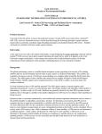
Catalog No.BKV0010
ISO 9001 / ISO 14001
Fluid Control Equipment
Proportional Control Valves
Series
Environmentally friendly
RoHS Compliant Product
e
t
a
R
Flow ility
Flexib
Three Advanced Features!
●Stepless variable control of gases and liquids
●High-precision hysteresis
(1/2 that of previous models)
●Initial setting possible without external input
Fluid Control Equipment
Proportional
Control Valves
Environmentally friendly
Series
RoHS compliant product!
The Proportional Control Valves KFPV050 Series was developed on the basic concepts of high
precision, efficiency, and simplicity.
In combination with the KFPC1 dedicated controller, it enables stepless adjustment of flow rates by
changing the magnitude of input signals to achieve high-precision control of air, gases, liquids, and
various types of media.
Proportional Control Valves
w
o
Fl
KFPV050 Series
e
t
Rc1/4 Direct Acting 2-port Valve, Plunger type
Ra
ity Stepless variable control of gas and liquid flow rate!
l
i
b
i
x
e
l
F
2
High-precision specifications
re 1
Featu
■
re
Featu
■
In combination with the KFPC1 Controller, it achieves high performance of
repeatability: 2% F.S. or less; response accuracy: 2% F.S. or less; and
low hysteresis: 5% F.S. or less.
■ Wiring versatility
Wiring can be installed freely in any direction to conform to machinery and device
mounting conditions, enhancing design flexibility.
90
360
(Body material:
SUS304)
● Possible wiring directions are every 90°,
top to bottom, and right to left.
● The solenoid orientation can also
be freely changed.
Controller for Proportional Control Valve
KFPC1
■ With
support circuits for initial setting!
re 3
Featu
Initial setting is possible without external input.
■ Highly reliable controller
(Body material: Brass)
q
K
●Standard input signals of 4 to 20mA or 0 to 10V
●RAMP response time can be adjusted in a range from 0 to 10 seconds to relieve large
fluctuations in the standard input signals.
●Monitor signals indicate the setting conditions and the solenoid
current values.
●Zero point switch-off function ensures valves
are completely closed.
●Built-in temperature compensation circuit
●Two potentiometers enable current value settings
at which the valve starts to open and at which
the valve is fully open to adapt application
requirements.
●LED monitor indicator
Caution
Before use, be sure to read the “Safety Precautions” on p.K.
p.e.
Example of connection circuit configuration
●Solenoid
SOL
●Solenoid
SOL
●FG
FG
●FG
FG
No polarity
Proportional Control Valves
KFPV050 Series
To the frame ground
●Monitor voltage (+) SV+
Voltmeter, etc. +
(mV)
●Monitor voltage (−) SV−
−
+
4 to 20mA, or 0 to 10V
−
●Input signal (+)
IN+
●Input signal (−)
IN−
●Power supply (+) 24V
PLC, etc.
●Power supply (−) 0V
+
DC24V
power supply −
Controller for Proportional Control Valve
KFPC1
Application Example
(Controlling water flow)
The KFPV050 Series changes the magnitude of the input signal to
achieve stepless control of flow rates.
This single control valve can cover what was previously done by
using several conventional ON/OFF-type solenoid valves to control
flow rates in a few steps.
CONTENTS
Safety Precautions . . . . . . . . . . . . . . . . . . . . . . . . . . . . . . . . . . . . e
K
Handling Instructions and Precautions . . . . . . . . . . . . . . . . . . . . t
K
Proportional Control Valves KFPV050 Series
Symbol and Specifications . . . . . . . . . . . . . . . . . . . . . . . . . . . . . . u
K
Inner Construction, Major Parts and Materials, Order Codes . . . i
K
Dimensions . . . . . . . . . . . . . . . . . . . . . . . . . . . . . . . . . . . . . . . . . o
K
Controller for Proportional Control Valve
KFPC1
Specifications, Major Parts and Functions, Order Code . . . . . . . !0
K
Dimensions . . . . . . . . . . . . . . . . . . . . . . . . . . . . . . . . . . . . . . . . . . !1
K
Flow Rate Conversion Graph . . . . . . . . . . . . . . . . . . . . . . . . . . . . !2
K
Explanation of Terms . . . . . . . . . . . . . . . . . . . . . . . . . . . . . . . . . . !4
K
w
K
Safety Precautions (Proportional Control Valves)
Always read these precautions carefully before use.
Before selecting and using the products, please read all the Safety Precautions carefully to ensure proper product use.
The Safety Precautions shown below are to help you use the product safely and correctly, and to prevent injury or damage to you, other
people, and assets beforehand.
Follow the Safety Precautions for: ISO4414 (Pneumatic fluid power—Recommendations for the application of equipment to
transmission and control systems), JIS B 8370 (Pneumatic system regulations)
The directions are ranked according to degree of potential danger or damage:
“DANGER!”, “WARNING!”, “CAUTION!”, and “ATTENTION!”
DANGER
Expresses situations that can be clearly predicted as dangerous.
If the noted danger is not avoided, it could result in death or serious injury.
It could also result in damage or destruction of assets.
WARNING
Expresses situations that, while not immediately dangerous, could become dangerous.
If the noted danger is not avoided, it could result in death or serious injury.
It could also result in damage or destruction of assets.
CAUTION
Expresses situations that, while not immediately dangerous, could become dangerous.
If the noted danger is not avoided, it could result in light or semi-serious injury.
It could also result in damage or destruction of assets.
ATTENTION
While there is little chance of injury, this content refers to points that should be observed for
appropriate use of the product.
■This product was designed and manufactured as parts for use in General Industrial Machinery.
■ In the selection and handling of the equipment, the system designer or other person with fully adequate knowledge and experience
should always read the Safety Precautions, Catalog, User’s Manual and other literature before commencing operation. Making
mistakes in handling is dangerous.
■ After reading the Instruction Manual, Catalog, etc., always place them where they can be easily available for reference to users of this
product.
■ If transferring or lending the product to another person, always attach the Instruction Manual, Catalog, etc., to the product where they
are easily visible, to ensure that the new user can use the product safely and properly.
■ The danger, warning, and caution items listed under these “Safety Precautions” do not cover all possible cases. Read the Catalog
and User’s Manual carefully, and always keep safety first.
DANGER
● Do not use the product for the purposes listed below:
1. Medical equipment related to maintenance or management of
human lives or bodies.
2. Mechanical devices or equipment designed for the purpose of
moving or transporting people.
3. Critical safety components in mechanical devices.
4. Food and beverage feeder units, etc.
This product has not been planned or designed for purposes that
require advanced stages of safety. It could cause injury to human
life.
● Do not use the product in locations with or near dangerous
substances such as flammable or ignitable substances. This
product is not explosion-proof. It could ignite or burst into flames.
● While the product is in operation, avoid touching it with your
hands or otherwise approaching too close. In addition, do not
make any adjustments to the interior or to the attached
mechanisms (connecting and disconnecting of wiring connectors,
piping tubes, or plugs) while in operation. It could result in
abnormal operation leading to injury.
● When mounting the product and workpiece, always firmly support
and secure them in place. Dropping or falling the product or
improper operation could result in injury.
● Persons who use a pacemaker, etc., should keep a distance of at
least one meter [3.28ft.] away from the proportional control valve.
There is a possibility that the pacemaker will malfunction due to
the strong magnet built into the product.
● Never attempt to remodel the product. It could result in abnormal
operation leading to injury, etc.
● Never attempt inappropriate disassembly, assembly of the
product relating to basic construction, or to its performance or
functions. It could result in injury, electric shocks, fire, etc.
● Do not splash water on the product. Spraying it with water,
washing it, or using it underwater could result in malfunction of the
product leading to injury, electric shocks, fire, etc.
WARNING
● Do not use the product in excess of its specification range. Such
use could result in product breakdowns, function stop, erratic
operation, or damage.
● Limit media to air, neutral gases, water, and other gases and
liquids that do not cause damage to component parts. As the use
e
of other fluids risks rapid degradation of operating performance or
a shorter operating life, be prepared to take responsibility for the
use of such media. In particular, use of corrosive fluids can lead to
stress corrosion cracks in the proportional control valve, resulting
in injury, electrical shocks, fire, etc.
● Before supplying media or electricity to the device and before
starting operation, always conduct a safety check of the area of
machine operation. Unintentional supply of media or electricity
could possibly result in electric shocks, or in injury caused by
contact with moving portion.
● Always cut off the power when performing wiring work. Leaving
the power on could result in electric shocks.
● Apply the specified voltage to the solenoid. Using the wrong
voltage level will prevent the solenoid from performing its function,
and could lead to breakage or burn damage of the product itself.
● Do not touch the terminal and the miscellaneous switches, etc.,
while the device is powered on. There is a possibility of electric
shocks and abnormal operation.
● Avoid scratching the cords such as lead wires. Letting the cords
be subject to scratching, excessive bending, pulling, rolling up, or
being placed under heavy objects or squeezed between two
objects, may result in current leaks or defective continuity that
lead to fire, electric shocks, or abnormal operation.
● Do not pull out the connectors while the power is on. In addition,
do not apply unnecessary stress on the connector. It could result
in erroneous equipment operation that could lead to personal
injury, equipment breakdown, or electrical shocks, etc.
● Always check the Catalog etc. to ensure that the product wiring
and piping is done correctly. Errors in wiring and piping could lead
to abnormal operation of the actuators, etc.
● In the first operation after the equipment has been idle for 48
hours or more, or has been in storage, there is a possibility that
contacting parts have been stuck, resulting in equipment
operation delays or sudden movements. For these first
operations, always run a test operation before use to check that
operating performance is normal.
● In low frequency use (more than 30 days between uses), there is
a possibility that contacting parts may have become stuck,
resulting in equipment operation delays or in sudden movements
that could lead to personal injury. Run a test operation at least
once every 30 days to confirm that movement is normal.
● Do not install the proportional control valves or the wiring that
controls them, near power lines where large electrical currents are
flowing, or in locations subject to strong magnetic fields or power
surges. Such application could lead to unintended operation.
● The proportional control valve can generate surge voltage and
electromagnetic waves when the device is turned off, affecting the
operations of surrounding equipment. Use solenoids with surge
suppression, or take countermeasures in the electrical circuits for
surges and electromagnetic waves.
● Do not use the product where ozone may be generated, such as
near ocean beaches or other places subject to direct sunlight or
mercury lamps. Ozone can cause rubber parts to deteriorate,
which can lead to degraded performance and functions, or to
equipment stoppages and functional shutdown.
● Do not throw the product into fire. The product could explode
and/or release toxic gases.
● Do not sit on the product, place your foot on it, or place other
objects on it. Accidents such as falling and tripping over could
result in injury. Dropping the product may result in injury, or also
damage or break the product resulting in abnormal or erratic
operation, or runaway etc.
● Repair work and maintenance, piping removal and installation,
other parts replacement, and any other kind of work operation
relating to the product, should be performed by a person or
persons with adequate knowledge and experience with the
product, media, fluid control systems, etc. Moreover, always
completely shut off the supply of media, and observe the
precautions listed below when performing these operations.
1. For gases, check that the pressure in the product and in the
piping connected to the product is down to zero prior to work
operations. In particular, be aware of the possibility of residual
air in the air compressor and air storage tank. Residual
pressure in the piping could cause the actuator to suddenly
move, resulting in injury.
2. For liquids, drain all liquids from the product and piping. With
corrosive fluids, in particular, there is a possibility of chemical
burns or contamination of surrounding areas.
3. For high-temperature media, in addition to the above
precautions, also check that the valve temperature has
dropped sufficiently. Accidentally touching the hot surface
could result in burn injuries.
● When it is necessary to keep the heat of the proportional control
valve using an antifreezing heater or thermal insulation material,
provide thermal insulation for pipes and the valve body only, and
do not attempt to insulate the solenoid area. That could lead to
coil burnout resulting in electric shocks, fire, or erratic operation.
● Use of the product under the conditions described below is
subject to regulation under the Japanese High Pressure Gas
Control Law. Be aware that violation of this law can result in
penalties to individuals or corporations:
Pressurized gases used at room temperature with gauge pressures of 1MPa [145psi.] or more, or pressurized gases capable of
reaching pressures of 1MPa [145psi.] or more converted at a
temperature of 35°C [95°F]. (Acetylene gas and liquefied gas are
subject to even stricter standards.)
For details, see the Japanese High Pressure Gas Control Law.
● When the proportional control valve is mounted inside a control
panel or is continuously energized for long periods, take heat
radiation measures to ensure that the ambient temperature of the
proportional control valve always remains within the specified
temperature range. In particular, caution should be exercised
regarding the continuous energizing of a fully opened proportional
control valve, because that could result in operational failure of
the temperature compensation circuit used to stabilize the
electrical current value against increased resistance when the
solenoid temperature rises.
● When energized for long periods, the coil will become quite hot.
Accidentally touching it could result in burn injuries.
● After finishing wiring operations, always check to ensure no wiring
connection error before turning on the power.
● Design equipment systems so as to avoid equipment damage or
personal injury, even in the event of operational failure of fluid
control equipment due to an emergency stop, power outages, or
other system abnormalities, such as an unintentional return to
non-energized status.
CAUTION
● Do not use the product in locations that are subject to direct
sunlight (ultraviolet), dust, salt, iron powder, humidity and high
temperature, or with the media and/or in the ambient atmosphere
that include organic solvents, phosphoric ester type hydraulic oil,
sulfur dioxide, chlorine gas, or acids, etc. It could lead to early
shutdown of function or a sudden degradation of performance,
and result in a reduced operating life. For the materials used, see
Major Parts and Materials.
● When mounting the product, leave room for adequate working
space around it. Failure to ensure adequate working space will
make it more difficult to conduct daily inspections or maintenance,
which could eventually lead to system shutdown or damage to the
product.
● For mounting or transport of heavy products, use a lift, supporting
tool, or several people, to provide firm support, and proceed with
due caution to ensure personal safety.
● Do not bring floppy disks or magnetic media, etc., within one
meter [3.28ft.] of the energized proportional control valve. There is
a possibility that the data on the floppy disks will be destroyed due
to the magnetism of the magnet.
● Do not use the proportional control valve in locations subject to
large electrical currents or strong magnetic fields. It could result in
erratic operation.
● Oil material from the compressor (excluding the oil-free compressor) can cause drastic deterioration in product performance that
may lead to a functional shutdown. Always install a mist filter
before pneumatic equipment to remove the oil material.
● If the media is a liquid, install a relief valve on the circuit to
prevent it from being a liquid-closed circuit. There is a possibility
that the valve may eventually fail to open.
ATTENTION
● When considering the possibility of using this product in situations
or environments not specifically noted in the Catalog or User’s
Manual, or in applications where safety is an important requirement such as in an airplane facility, combustion equipment,
leisure equipment, safety equipment and other places where
human life or assets may be greatly affected, take adequate
safety precautions such as an application with enough margins for
ratings and performance or fail-safe measures. Be sure to consult
us with such applications.
● Always check the Catalog and other reference materials for
product wiring and piping.
● When handling the product, wear protective gloves and a mask,
safety glasses, safety boots, etc. to keep safety.
● When the product can no longer be used, or is no longer
necessary, dispose of it appropriately as industrial waste.
● Proportional control valves can exhibit degraded performance and
function over its operating life. Always conduct daily inspections of
the equipment, and confirm that all requisite system functions are
satisfied, to prevent accidents from happening.
● Leaks from the proportional control valve are not zero. For
application of requiring holding pressure inside the pressure vessel,
consider adequate margin of capacity and holding time in design of
the system.
● For inquiries about the product, consult your nearest Koganei sales
office or Koganei overseas department. The address and telephone
number is shown on the back cover of this catalog.
OTHERS
● Always observe the following items.
1. When using this product in fluid control systems, always use
genuine KOGANEI parts or compatible parts (recommended
parts).
When conducting maintenance and repairs, always use
genuine KOGANEI parts or compatible parts (recommended
parts). Always observe the required methods and procedure.
2. Do not attempt inappropriate disassembly or assembly of the
product relating to basic construction, or its performance or
functions.
Koganei cannot be responsible if these items are not properly
observed.
r
Handling Instructions and Precautions
General precautions
Mounting and piping
Atmosphere
11. Mounting and piping should be performed by a person or
persons with adequate knowledge and experience by using
appropriate tools.
12. While any mounting direction is acceptable, the best direction is one that ensures the main body not being directly
subjected to shocks or vibrations. Moreover, mounting so
that the solenoid portion faces upward is recommended to
prevent accumulation of foreign material, etc.
13. When connecting tubes to the Proportional Control Valve,
flush the tubes completely (by blowing compressed air)
before piping to prevent metal chips, sealing tape, rust, etc.,
generated during plumbing from entering inside the piping.
14. Mount a filter or a strainer near the proportional control
valve to remove solid particles from the media. Accumulation of solid particles inside the proportional control valve
could result in defective operation or damage to the proportional control valve. Use a filter or a strainer of about 80 to
120 mesh.
15. Take caution that the filter and strainer do not become
clogged. When the pressure drop reaches 0.1MPa
[14.5psi.], clean the strainer.
16. Check the direction of the fluid flow.
17. Use sealing tape to seal the piping connections.
When using sealing tape, wrap it so that 1.5 to 2 threads
remain (see below).
ap
e
Wrapping
direction
S e a li n g t
Rem
ain
abo
ut 2
thre
ads
When screwing in piping or fittings, be careful to prevent
thread shavings or sealant materials from entering inside
the proportional control valve.
18. When tightening piping, be sure to hold the metallic parts of
the main valve body. Do not apply any force to the solenoid
plastic mold portion. Applying force there could cause damage to the solenoid.
19. When engaged in piping work, do not apply external force to
the proportional control valve. Application of external force
could cause damage to the proportional control valve.
10. When screwing piping or fittings into the proportional control
valve, tighten to the appropriate tightening torque, as listed
below.
Connection thread
Tightening torque N·m [ft·lbf]
Rc1/4
11.77∼13.73 [8.68∼10.13]
11. Do not loosen or tighten the thread with the adhesive material used on the top of the proportional control valve. Such
action could prevent normal operation of the proportional
control valve.
12. When mounting the proportional control valve inside a control panel or when energizing it for long periods, consider
providing heat radiation measures such as ventilation.
t
Avoid using the proportional control valve in the locations and
environments listed below, as it could result in malfunction of
the product. If use in such conditions is unavoidable, always
provide a cover or other adequate protective measures.
● Location directly exposed to dripping water or oil
● Environment where the valve body is subjected to dew
condensation
● Location directly exposed to metal chips, dust, etc.
Storage
For long-term storage after using water as a medium, be sure to
completely remove any water remaining inside. Residual water
could result in rust, defective operation, and deterioration of
seal materials.
Wiring instructions
Solenoid
1. The solenoid can be moved freely to any orientation.
Limit the tightening torque for the hexagon nut securing the
solenoid in place to within the amount shown below.
1. Electrical connection: When using a DIN connector (KFPZ39), insert a gasket and connect it to the solenoid’s flat
contacts. (Limit the cable length to 50m [164ft.] or less.)
FG
(Ground for valve)
Hexagon nut
SOL
(No polarity)
Can be moved freely to any orientation
Model
Tightening torque N·m [ft·lbf]
KFPV050
2.8 [2.1]
2. While any mounting direction is acceptable, mounting so that
the solenoid portion faces upward is recommended to prevent accumulation of foreign material, etc.
SOL
(No polarity)
● Avoid installing wiring parallel to high voltage lines or
power lines, or within the same conduit. In addition, install
wiring in locations as far removed from motors as possible.
Installing in such locations can cause erratic operation. If
installation near inductive loads or power lines is unavoidable, always take load surge suppression measures, and
use magnetic shields. Use particular caution in environments that are subject to excessive external electrical
noise, because of the high risk of erratic operation.
2. The tightening torque for the DIN connector mounting thread
should be 0.3N·m [2.7in·lbf].
Precautions for Use
1. If planning to use any media other than the specified media, carefully consider the
compatibility of that media with the valve body and seal materials, and be prepared to take
responsibility for such use.
● Rising temperatures, increasing fluid densities, use of ultra-pure fluids, etc., risk hastening
the rate of corrosion.
● For such use, always run sample tests beforehand to check compatibility with the media
under actual application conditions.
2. The control characteristics will vary depending on the application and setting conditions. To
use the valve, test the on-site control systems under actual application conditions, and fully
perform checks for responsiveness, stability, effectiveness, and other characteristics.
y
Proportional Control Valves
Series
Rc1/4 Direct Acting 2-port Valve,
Plunger type
Use the proportional control valve in combination
with the KFPC1 controller.
For details of the controller, see p.!0.
Symbol
Basic Models and Functions
Model
KFPV050
Item
Number of positions
P
A
2 positions
Number of ports
2 ports
Circuit configuration
Normally closed (NC)
Normally closed (NC)
Common Specifications
Basic model
KFPV050
Item
Media Note 1
Air, neutral gas, water (other gases and liquids that do not cause damage to component parts)
FKM
Seal material
Brass or stainless steel
Valve body material
Media temperature range
–10∼90 [14∼194] (no freezing allowed)
°C [°F]
Operation type
Direct acting type
Ambient temperature range
°C [°F]
0∼55 [32∼131]
21×10– 6 [2.26×10– 4] or less
m2/s [ft.2/sec.]
Media viscosity
Mounting direction Note 2
Any
IP65 equivalent
Environmental protection code
Notes: 1. For the component part materials, see p.i, Inner Construction and Major Parts.
2. Mounting so that the solenoid portion faces upward is recommended to prevent accumulation of foreign material, etc.
Detailed Specifications
● Seal Material: FKM
Item
Port size
Models
Orifice
diameter
Effective area
Operating
pressure
differential range
Maximum
operating
pressure
mm2
MPa [psi.]
MPa [psi.]
Flow rate
Cv
mm [in.]
KFPV050-2-20
Rc1/4
2.0 [0.079]
0.13
2.3
0∼0.7 [0∼102]
KFPV050-2-30
Rc1/4
3.0 [0.118]
0.22
4.0
0∼0.35 [0∼51]
KFPV050-2-40
Rc1/4
4.0 [0.157]
0.31
5.7
0∼0.2 [0∼29]0
Note: Allowable voltage fluctuation range: Rated voltage ±10%
u
3.5 [508]
Rated
voltageNote
DC24V
Power
consumption
W
8
Coil current
Mass
MAX.: mA
g [oz.]
300
550 [19.4]
Inner Construction and Major Parts
Parts
No.
!1
!0
o
i
u
y
t
r
e
w
OUT
q
IN
Materials
q
Valve body
w
Plunger seal
e
O-ring
r
Guide tube
t
Plunger
y
Wear ring
u
Spring
i
Stopper
SUS304
o
Solenoid
Polyester
!0
Lock nut
Free-cutting steel (nickel plated)
!1
DIN connector
Brass or SUS304
FKM
FKM
SUS304
Magnetic stainless steel
PTFE
SUS304
Plastic
Characteristics
● Characteristics Curve
Characteristics when used in combination with
KFPC1 Controller
Hysteresis
%F.S.
5 or less
Repeatability
%F.S.
2 or less
Response accuracy
%F.S.
100%
2 or less
10:1
Range ability
Cautions: 1. The characteristics curve at right shows the ratio of the
measured flow rate (under Koganei test conditions) to the
control signal input (electric current, voltage) with the maximum
flow rate as 100% .
2. Since flow rate characteristics will vary depending on the
application and setting conditions, check them under actual
application conditions.
Flow rate
Remark: Measurement performed under Koganei measurement conditions.
0%
0%
(0V)
(4mA)
100%
(10V)
(20mA)
Control signal input
Proportional Control Valve Order Codes
■ Circuit
■ Orifice
configuration
diameter
-2:2-port
■ Seal
material
-20:φ2.0mm
-30:φ3.0mm
-40:φ4.0mm
-FM:FKM
■ Valve body
material
■ Port size
-BR:Brass
-S4:SUS304
-02:Rc1/4
■ Piping
■ Voltage
specification
-39:With DIN
connector
-39N:Without
DIN
connector
DC24V
Model
-20
KFPV050
-2
-30
-FM
-BR
-S4
-02
-39
-39N
DC24V
-40
●The Controller is sold separately; place a separate order for it.
● Order code for the connector only
DIN connector standard type
( 27mm [1.06in.])
KFPZ-39
i
Dimensions
mm [in.]
Proportional Control Valve
KFPV050
IN
46
[1.811]
Appliable cable
outer diameter
φ4 [0.157]∼φ11 [0.433]
71.8 [2.827]
2-Rc1/4
37.2 [1.465]
47.5 [1.870]
11
[0.433]
OUT
83.7 [3.295]
43 [1.693]
33 [1.299]
(53 [2.087])
26.5 [1.043]
50.1 [1.972]
17 [0.669]
(Width across flats)
-39: D
I
N connector
(-39 or to be
ordered separate
part KFPZ-39)
32
[1.260]
4.5 [0.177]
24
[0.945]
24
[0.945]
4-M4×0.7
Depth 7 [0.276]
o
Controller for Proportional Control Valve
For Proportional Control Valves KFPV050 Series
Specifications
Model
KFPC1-F07-DN DC24V
Item
Mounting type
DIN rail mounting type
4∼20mA
Signal input
Ω
Input impedance
0∼10V
220
Power supply voltage
1.2M
DC24V±10%
Valve control signal
PWM (pulse width modulation)
Ambient temperature range (atmosphere) °C [°F]
0∼50 [32∼122] (no condensation allowed)
Maximum allowable load current
A
1.1
Power consumption (for control circuit)
W
0.55
Directly proportional to the solenoid current, 1mV = 1mA
Monitor signal
RAMP response time
s
0∼10
Major Parts and Functions
Potentiometer MAX
Potentiometer MIN
Connection
terminals
SOL
POW
MAX
MAX
MIN
AUTO
SOL
FG
MIN
SW2
FG
RAMP
SV+
SV−
IN+
IN−
Slide switch SW2
Vertically in order
from top
MAX
MIN
AUTO
ON
1 2 3 4 5 6
ON
OFF
Potentiometers
MAX:
For setting current value I2 at which the valve is
fully open
MIN:
For setting current value I1 at which the valve starts
to open
RAMP: For setting RAMP response time (0 to 10s)
Potentiometer RAMP
LED indicator
POW:
Lights up when current is flowing to the solenoid
DIP switch SW1
DIP switches
SW1
1∼3 (SIGNAL):
SW1
24V
0V
Connection terminals
SOL:
Valve actuation output (no polarity)
SOL:
Valve actuation output (no polarity)
FG:
Ground for valve
FG:
Frame ground for power
Monitor output (+)
SV+:
SV−:
Monitor output (−)
Standard signal input (+)
IN+:
Standard signal input (−)
IN−:
24V:
Power supply input (+)
0V:
Power supply input (−)
4, 5 (PWM):
6 (ZERO):
● Order Code of the Controller for
Proportional Control Valve
Selects standard signal input
(4 to 20mA, or 0 to 10V)
Switches between PWM frequencies
Sets the zero point switch-off function
Slide switches
SW2
MAX:
Input signal MAX
MIN:
Input signal MIN
AUTO:
Input signal AUTO (operating mode)
KFPC1-F07-DN DC24V
!0
Dimensions
mm [in.]
Controller for Proportional Control Valve
KFPC1-F07-DN
MAX
POW
SOL
MAX
MIN
AUTO
FG
FG
84.7 [3.335]
81 [3.189]
SOL
MIN
RAMP
SV+
SVON
OFF
IN+
IN-
1 2 3 4 5 6
24V
SIGNAL PWM ZERO
0V
142942
(67 [2.64])
Remark: For Controller instructions , see the User’s Manual packaged with the product.
!1
(60 [2.36])
(50 [1.97])
30.2
[1.189]
41 [1.614]
Flow Rate Conversion Graph (water, air)
● Water: Flow rate conversion graph
500
Cv5
100
Flow rate R/min
50
Cv1
Cv0.5
10
5
Cv0.1
Cv0.05
1
0.1
0.01
0.05
0.1
Pressure difference ΔP MPa
0.5
1
1R/min = 0.0353ft.3/min.
1MPa = 145psi.
Remark: The pressure difference ΔP in the graph shows the pressure difference between the primary (upstream) gauge pressure
P1 and secondary (downstream) gauge pressure P2.
ΔP=P1−P2 (MPa)
Flow rate equation (in the equation, pressures Ph and Pl show absolute pressure)
Q=45.62Cv
√ ̄
 ̄ ̄ ̄
Ph−Pl
√ ̄
 ̄
G
Q'=0.1338Cv
'−Pl
√ ̄
 ̄ ̄'
Ph ̄
√ ̄
 ̄
G
Q : Flow rate R/min
Cv : Flow rate coefficient
Ph : Primary (upstream) absolute pressure (Mpa)
Pl : Secondary (downstream) absolute pressure (Mpa)
G : Specific gravity (for water, this equals 1)
Q' : Flow rate ft.3/min.
Cv : Flow rate coefficient
Ph' : Primary (upstream) absolute pressure (psi.)
Pl' : Secondary (downstream) absolute pressure (psi.)
G : Specific gravity (for water, this equals 1)
How to use the graph
When there is no diagram for the valve flow rate
coefficient (Cv) in the above graph:
Multiply the Cv of the valve being used by the flow
rate at Cv = 1 read out from the graph to calculate the
flow rate.
Example: At Cv = 1, value read out from the graph:
Q=20R/min [0.706ft.3/min.] for the desired
pressure difference
When the flow rate coefficient for the valve
being used is Cv = 0.3
The flow rate is found by using the below
equation
Q×Cv=20×0.3=6.0R/min [0.212ft.3/min.]
!2
Flow Rate Conversion Graph (water, air)
● Air: Flow rate conversion graph Cv = 1
Primary (upstream) pressure
P1 (MPa)
2000
P1=1
P1=0.9
1500
P1=0.8
P1=0.7
Flow rate
P1=0.6
P1=0.5
1000
P1=0.4
P1=0.3
P1=0.2
500
0
P1=0.1
0
0.1
0.2
0.3
0.4
0.5
0.6
0.7
0.8
0.9
1
Secondary (downstream) pressure P2 (MPa)
1R/min = 0.0353ft.3/min.
1MPa = 145psi.
Remark: Pressures P1 and P2 in the graph show the gauge pressure (MPa).
How to use the graph
Flow rate equation
(in the equation, pressures Ph and Pl show absolute pressure)
1) When Pl / Ph>0.5283
The above graph shows the flow rate when the flow rate
coefficient Cv = 1.
/ 1, multiply the Cv of the valve being used by the
When Cv=
flow rate read out from the graph to calculate the flow rate.
Q=4119Cv
√
 ̄ ̄ ̄ ̄ ̄ ̄
(Ph−Pl)
Pl
√ ̄
 ̄
G
2) When Pl / Ph≦0.5283
Q=2056CvPh
1
√ ̄
 ̄
G
Example: Value read out from the graph:
Q=500R/min [17.65ft.3/min.] (ANR) for the desired
P1 and P2
When the flow rate coefficient for the valve being
used is Cv=0.3
The flow rate is found by using the below equation
Q×Cv=500×0.3=150R/min [5.30ft.3/min.] (ANR)
Q : Flow rate R/min (ANR)
Cv : Flow rate coefficient
Ph : Primary (upstream) absolute pressure (Mpa)
Pl : Secondary (downstream) absolute pressure (Mpa)
G : Specific gravity (conversion specific gravity, when air is 1)
1) When Pl' / Ph' >0.5283
Q'=1.0Cv
') ̄
√ ̄
 ̄'−Pl
 ̄ ̄ ̄
(
Ph
Pl'
√ ̄
 ̄
G
2) When Pl' / Ph' ≦0.5283
Q'=0.5CvPh'
!3
1
√ ̄
 ̄
G
Q' : Flow rate ft.3/min. (ANR)
Cv : Flow rate coefficient
Ph' : Primary (upstream) absolute pressure (psi.)
Pl' : Secondary (downstream) absolute pressure (psi.)
G : Specific gravity (conversion specific gravity, when air is 1)
Explanation of Terms
● Consumption power
For direct current, this is the multiplied value of the product’s
DC voltage and effective current value, and the unit used is W.
● Hysteresis
A characteristic of equipment
with different output values due
to the directional applied input
values.
Output
● Cv
A coefficient of flow rate, this is used to express a water flow
rate in US gal/min when flowing through the valve at a pressure
differential of 1lbf./in2 (1psi.) at a temperature of 60°F (15.5°C).
Input
● Kinematic viscosity
The viscosity
of a fluid divided by the density
of a fluid
with identical conditions (temperature, pressure), as expressed
. Represents the magnitude of resisin the formula
tance when a liquid flows due to the action of its own mass.
The most commonly used unit of kinematic viscosity is the cSt
(centi-Stokes), which in SI units is m2/s (square meter per second). Another unit used is St (Stokes). For example, m 2/s
(square meter per second) expresses the kinematic viscosity of
a fluid for which the density is 1kg/m 3 and the viscosity is
N S/m2 (Newton-seconds per square meter).
A conversion table for each of these units is shown below.
m2/s
St
cSt
1
1×10⁴
1×10⁶
1×10⁻⁴
1
1×10²
1×10⁻⁶
1×10⁻²
1
● Maximum operating pressure
The maximum pressure to which the proportional control valve
can be pressurized during operation.
● Operating pressure differential
The difference between the inlet pressure and the outlet pressure, by which the proportional control valve can operate.
● Operating pressure differential range
The range between the upper limit of the operating pressure differential (maximum operating pressure differential) and the
lower limit (minimum operating pressure differential).
● Orifice diameter
The narrowest part of the flow path inside the valve, with a relatively short length when compared to the cross-section
dimensions. In other words, the cross-section area at the constricted location is converted into a circular cross-section area
and then expressed as a diameter.
● PID control P action: Proportional action
I action: Integral action
D action: Derivative action
This control consists of three control actions, including
proportional action (P action); a control action in which the
output of a control device is proportional to the input, integral
action (I action) when output is proportional to the integration of
input, and derivative action (D action) when output is
proportional to the derivation of input.
(
)
● Pulse Width Modulation (PWM)
When the frequency band is F [Hz], a signal is completely determined by the value of signal samples at 1/2F [S] (Sampling
Theorem). Based on this theorem, all information from sampled
modulation signals (such as voice, etc.) can be expressed in
pulse rows, a technique known as pulse modulation. A number
of methods are available. In pulse width modulation, one of
these methods, a pulse width with a fixed amplitude, is used to
change the amplitude information of samples in the sampled
modulation signal.
Voice and other modulation signals
Sampled modulation signals
Pulse width modulation
● RAMP response
Time response when shifting input from a no-change state to a
state in which change occurs at a fixed speed.
● RAMP response time
In RAMP response, the time required for a value obtained by
subtracting a first-order steady-state deviation of the output
from the input multiplied by the static gain, falls within a specified tolerance range (for example, 5%).
● Range-ability
A ratio between the maximum and minimum flow rate
coefficients Cv in a controllable operation. For example, if the
range-ability is 10 : 1, a valve with a maximum flow rate
coefficient Cv of 10.0 has a minimum flow rate coefficient Cv of
1.0.
● Temperature compensation
This is a characteristic of electronic parts. In general, changes
in temperature or generation of heat can cause changes in the
set electrical current and voltage levels, in a phenomenon
known as temperature drift. An operation to compensate for this
temperature drift is called temperature compensation.
● Viscosity
Index expressing the degree of internal friction accompanying a
fluid flow. Also known as absolute viscosity to distinguish it from
kinematic viscosity.
!4
Limited Warranty
KOGANEI CORP. warrants its products to be free from defects
in material and workmanship subject to the following provisions.
Warranty Period
Koganei
Responsibility
Limitations
The warranty period is 180 days from the date
of delivery.
If a defect in material or workmanship is found
during the warranty period, KOGANEI CORP.
will replace any part proved defective under
normal use free of charge and will provide the
service necessary to replace such a part.
•
This warranty is in lieu of all other warranties,
expressed or implied, and is limited to the
original cost of the product and shall not
include any transportation fee, the cost of
installation or any liability for direct, indirect
or consequential damage or delay resulting
from the defects.
•
•
•
•
KOGANEI CORP. shall in no way be liable or responsible for
injuries or damage to persons or property arising out of the use
or operation of the manufacturer’s product.
This warranty shall be void if the engineered safety devices
are removed, made inoperative or not periodically checked for
proper functioning.
Any operation beyond the rated capacity, any improper use or
application, or any improper installation of the product, or any
substitution upon it with parts not furnished or approved by
KOGANEI CORP., shall void this warranty.
This warranty covers only such items supplied by KOGANEI
CORP. The products of other manufacturers are covered only by
such warranties made by those original manufacturers, even
though such items may have been included as the components.
The specifications are subject to change without notice.
URL http://www.koganei.co.jp
E-mail: [email protected]
OVERSEAS DEPARTMENT
3-11-28, Midori-cho, Koganei City, Tokyo 184-8533, Japan
Tel: 042-383-7271 Fax: 042-383-7276
MICHIGAN REPRESENTATIVE OFFICE
5070 East N Ave., Kalamazoo, Michigan, 49048, U.S.A.
Tel: 269-388-8769 Fax: 269-388-8771
SHANGHAI KOGANEI INTERNATIONAL TRADING CORPORATION
Room 2606, 2607 Tongda Venture Building No. 1, Lane 600,
Tianshan Road, Shanghai, 200051, China
Tel: 021-6145-7313 Fax: 021-6145-7323
6/’06 30 BPBP
©KOGANEI CORP. PRINTED IN JAPAN
RECYCLED PAPER