1
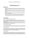
Figure 6-40. Transmission Parameters tab. This tab allows you to configure the channel reception of the PLC coupling board and the PLC coupling board plugged. Note the warning message displayed before to continue, check the proper voltage to use (VDD selection). In this example, the firmware load is for ATPLCOUP001 board, so that, it is only designed for PRIME channel 1. Selecting the option Perform EVM Test you can change the message and interval of transmission in order to make a test that evaluates the PHY layer performance. For more information check application note, doc43072. The Perform EVM Test box is disabled by default. Click the Next button to continue. Following figure (Figure 6-41) shows the TX Test Parameters tab. This tab is where transmission test parameters are configured: Time Interval (milliseconds): desired interval between frame transmissions. Number of Frames: number of frames to be transmitted. Message: ASCII message to be transmitted. These parameters must match the reception test parameters (Figure 6-36) for the test to be successful. 62 SAM4CP16B-EK Kit User Manual [USER GUIDE] 6 Atmel-43054E-ATPL-SAM4CP16B-EK-Kit-User-Manual-UserGuide_03-Nov-2015 2