1
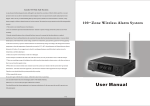
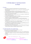
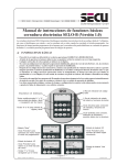
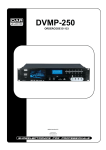
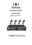
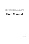
Long-distance Intelligent Alarm System
User's Manual
Please read this manual carefully before you operate
July,2006 Publish
Long-distance Intelligent Alarm System
Long-distance Intelligent Alarm System
1 Introduction
Table Of Contents
1 Introduction ------------------------------------------ 2
2 Diagram Of System Components ------------------ 2
3 Definition -------------------------------------------- 3
4 Operate Precautions--------------------------------- 4
5 Main Functions And Characteristics ----------------5
6 Name Of Main Parts --------------------------------- 6
7 Operate Introduction ---------------------------------9
7.1Sound And Light Indication --------------------- 9
7.2 Program Guide O f A larm H ost ------------------9
<1> How To E nter P rogram S tate ---------------- 9
<2> How To Inquire L og ------------------------10
<3> How To Set Time -----------------------------10
<4> How To Set Timer -open -------------------- 11
<5> How To Set Timer -c lose --------------------11
<6> How To Set Telephone Numbers ------------12
<7> How To Modify Password ------------------13
<8> How To Record And Play Record--------14
<9> How To Set Zone Bypass --------------------14
<10> How To Enter Code ------------------------- 15
<11> Alarm Introduction------ ------------------- 1 6
<12> How To Manage Alarm Via Telephone ----17
<13> Additional Commands --------------------- 17
<14> Ex-factory Default State--------------------1 8
7.3 How To Set KS-200ATI/BTI Transmitter ----- 18
8 The Usage And Maintenance Of Micro-printer---- 20
9 Main Technology Index ----------------------------- 23
10 Standard Packing List ---------------------------- 24
11 Optional Packing List ---------------------------- 24
12 Simple Failure Recovery -------------------------25
1
Long-distance wireless alarm system characteristics of long-distance
and super-large capacity, which adopts special digital signal
processing chip to manage 299 or 999 kinds of wireless detectors at
the same time. Its receive sensitivity is high, so it can receive signals
at the distance of 1-10 kilometers. The super-large digital pipe
displays for message. It makes alarm on the spot and alarm message
can be printed real time. It also can dial pre-set telephone numbers,
and report alarm message in pure Chinese/English when receiving
alarm signal. It connects with managing center computer by RS232
interface. Computer displays alarm information on electric map and
tells from alarm types when receiving alarm signal. It is suitable for
enterprise, family, office building, police station to guard against
theft, ask for help and joint defense for public security.
2 Diagram Of Components
Long-distance wireless alarm system is composed of KS-200 A
receiver, all kinds of passive infrared detectors, door
sensors, infrared correlations, smoke detectors etc.
<1> Alarm Host
It adopts special digital signal processing chip to manage 299 or
999 kinds of wireless detectors at the same time. Its receive
sensitivity is high, so it can receive signals at the distance of 1-10
kilometers. And the detector code can be learned to main unit by
entering code manually or by triggering detector. Message is
displayed on super-large LED. It makes alarm on the spot, and the
alarm message can be printed real time. It also can dial pre-set
telephone numbers, and report alarm message in Chinese/English
when receiving alarm signal. It connects with manage center
computer by RS232 interface. Computer displays alarm
information on electric map and tells from alarm types when
receiving alarm signal.
<2> Wireless Infrared Detector
KS-200 ACT Wireless Infrared Detector adopts double infrared
sensor together with single chip processing technology and automatic
temperature compensation technology. It has advantages of low
misinformation rate and high anti-interference capability. Build-in
rechargeable battery can be used as backup power. It can charge and
switch between AC and DC automatically.
KS-200ATI Wireless Infrared Detector: Based on KS-200ACT ,
KS-200ATI increases functions to arm or disarm by wireless
2
Long-distance Intelligent Alarm System
Long-distance Intelligent Alarm System
remote controller and to transmit wirelessly. It can be used together
with short-distance wireless detectors and remote controllers. Buildin rechargeable battery can be used as backup power. And It can
charge and switch between AC and DC automatically. And it will
make alarm sound when battery low power.
KS-200BTI Wireless Infrared Detector: Based on KS-200ATI,
KS-200BTI increase functions to alarm on the spot for 30 seconds,
Build-in rechargeable battery can be used as backup power. And It can
charge and switch between AC and DC automatically. And it will
make alarm sound when battery power lower.
Wired
Emergency Button
KS-200DCT Wireless
PIR Detector
KS-200AT/KS-200ACT
PIR Detector
KS-50A Wireless Emitter
Wired
KS-20BW
Wireless Door Sensor
KS-200ATI PIR Detector
KS-50AI Wireless Emitter
Positive PIR Detector
<3> Wireless Transmitter
KS-200DCT
Wireless PIR Detector
KS-50AI Wireless Transmitter adopts 8-bit single chip as
processing core. It provides power to wired detectors and transmits
(open/close) signal of wired detector to the signal which can be
recognized by KS-200A series alarm host. KS-50AI can be armed or
disarmed by wireless remote controller and rechargeable battery can
be used as backup power. It also can adjust automatically between AC
and DC. And it can greatly save cost.
Wireless Smoke Detector
KS-200BTI PIR Detector
KS-50AI Wireless Emitter
Wired
KS-10 Series Wireless
Remote Controller
Microwaves/+PIR Detector
KS-200BTI PIR Detector
Log
Time Timer-Open
Timer-Close
Telephone
Password
Record
Bypass
code enter Channel
KS-10 Series Wireless
Remote Controller
Wireless Caller
Wireless Emergency Button
3.Definition
KS-20BW
Wireless Door Sensor
SET
OK
PRINT
KS-200A
RESET
Long-Distance Wireless Alarm System
Arm: The system enters into defense state to receive alarm signal..
Disarm: The system cannot receive alarm signal in any zones (except
for emergency zone and emergency caller) .
Emergency Zone: The system can receive signal whatever states it is.
It also refers to 24 hours zone.
User’ Code: Be used by users to operate.
Installer Code: Be used by installer or administrator to operate .
Transmit Wirelessly : According to transmit address code, wireless
transmitter can transmit signal made by wireless detector to the signal
which can be recognized by KS-200A . It also refers to relay
wirelessly. And it can greatly save cost.
Sound Composed By Computer: A sentence composed by computer
with different segments pre-recorded.
Code Entering: Alarm host and detector are working independently,
so the code of detector should be learned to alarm host, and alarm
host can receive signals when detector triggered..
3
Line
PSTN
Telecommunication Office
Computer
Mobile
Telephone
Picture 1
4.Operate Precautions
*Please carefully read the user’s manual and pay attention to labels
and directions on alarm host before operation. Check whether all
wire connections are correct and then turn it on to test so as to
prevent occurrence of accidents.
*The alarm host can be equipped with 12V7Ah sealed lead -acid
storage cell. The battery stand-by time is longer than 72 hours. If
power failure often occurs in defense area, battery with larger
capacity is recommended to serve as backup power.
4
Long-distance Intelligent Alarm System
Long-distance Intelligent Alarm System
*During programming. If wrong code has been entered for three time
continuously, the alarm host will make alarm sound for 30 seconds, if
you press any keys during the time, the alarm time will be increased for
30 seconds.
*This main unit is wireless, so it is recommended to register in your
local frequency authorized institution before installing.
*Please do not disassemble alarm host at will so as not to cause
accidents or damage the main unit.
*Please contact the client service department or local distributor in time
if there are something wrong, and do not disassemble or maintain it
by yourself.
*Please periodically perform check-up so as to clear troubles in time
and avoid to fail to report alarm message.
5 Main Functions And Characteristics.
*It has 1-299 or 999 independent wireless zones; each can be armed or
disarmed independently. It also can be defined to common zone and
emergency zone.
*The code of detector or wireless emitter can be learned to alarm host
automatically or by hand.
*Super-large LED display and voice guide make alarm more easily.
*Two codes (user code and installer code) manage independently.
The code is modifiable to prevent program from distorting at ill will.
*Two groups of time can be set for time switch, and it checks present state
automatically and indicates present (on/off) state.
*Five pieces of up-to date alarm message can be scrolled to display
simultaneously.
*Inquiring 100 pieces of up-to-date records (including alarm message
indicate message and arm/disarm message.
*A normal open/close output and +12V DC output are provided to
control other devices(e.g. startup alarm siren, alarm light, alarm
linkage etc.)
*Provide a group of sound signal output, which can connect directly with
8Ω15W passive trumpet and sound box, and build-in trumpet will be
invalid automatically.
*Micro printer can print 5 pieces of alarm records simultaneously, and
also can print them one by one.
*It equipts with telephone module, and it dials pre-set telephone
numbers automatically and report alarm message in pure English
when receiving alarm signal.
*Networking module can be connected with computer by RS232
interface and display and manage alarm message real time.
*Internal or external backup battery are optional. And it will
indicate when over-charged,over-discharged, battery low power .
5
6.Name And Usage Of Main Parts
6.1 KS-200A Alarm Host
6.1.1 Front Panel Of Alarm Host (Picture 2)
<1> Volume Button: Volume becomes louder when adjusted clock
wisely. But it is invalid for indicate sound.
<2> 0-9 Keys: Number keys
<3> <*, #> Key: Right/left direction key, used to complete seting up
functions together with “ SET” key.
<4> RESET Key: When alarm occurs, press this key to stop alarming
and the alarm records will be keep automatically. After entering
setup state, press this key to exit to the upper menu.
<5> PRINT Key: Print when inquiring records, sometimes it is used
to complete setting up function with “SET” key.
<6> OK Key: Used to confirm the inputs, and complete function
together with “SET” key.
<7> SET Key: Used to set up functions. Please referring to
“Operation Guide” chapter for specific operations.
<8> Micro-printer: Used to print.
<9> LED Display Screen: Usually, it displays time, and the second
light is flashing. When alarm occurs, it displays alarm time, alarm
orientation and alarm type. And the second light is completely on.
After entering into set up state, it displays the setting contents.
<10> Menu : In stand-by time, the light of menu is off. When
Enering into setup state, the light is flashing, after entering into
setup state of some menu, the light of this menu is completely on.
6.1.2 Back Panel Of Alarm Host (Picture 3)
Log
Time Timer-Open
Timer-Close
Telephone
Password
Record
Bypass
code enter Channel
AC 220V 50HZ
FUSE 0.5A
ANTENNA
V+GND
DC INPUT +12V
KS-2 0 0A
LINE PHONE
RS 232
SPEAKER
Long-Distance Wireless Alarm System
Picture 3
Picture 2
6
Long-distance Intelligent Alarm System
Long-distance Intelligent Alarm System
<1> AC Power Input Interface: AC 220V 50Hz power supply.
<2> Fuse: AC220V 0.5A tube fuse.
<3> Antenna Interface: It can be connected with indoor antenna and
outdoor antenna. In order to get the best affection, outdoor antenna
is recommended.
<4> DC input interface: Polarity: red is+, Black is -, It can be
connected when large capacity backup battery is needed. It can
automatically charge and adjust between AC and DC . Short
circuit is forbidden. If build-in backup power supply is selected.
voltage input to this interface is forbiddened.
<5> Outside Line Socket: To be connected with PSTN.
<6> Extension Socket : To be connected with telephone set.
<7> RS232 Interface: To be connected with serial-port of computer.
<8> Sound Signal Output: It can be connected directly with 8Ω 15W
passive trumpet and sound box; build-in trumpet will be invalid
automatically.
<9> Alarm Output Interface: Provide a set of normal open and a set of
normal close alarm output and a set of uncontrolled +12V 500mA
output.
<10> Normal Open, Normal Close Alarm Output Interface: T here is
label on the back panel; Alarm output contact it can load is 1A 120
V AC or 3A 30V DC.it is used to control other devices when alarm
occurs. It is not allowed to connect directly when the power of
device over its load. To avoid damaging alarm host, it needs
adopting auxiliary relay.
<11> Uncontrolled DC Output Interface: V+ end and GND end
provide other devices with +12V-13.8V 500mA DC output, V+ end
is anode. C end is cathode.
AC 220V 50HZ
FUSE 0.5A
ANTENNA
Picture 4
V+GND
DC INPUT +12V
LINE PHONE
RS 232
SPEAKER
Red
Black
Active Siren
(Acoustics or Active Efficiency)
7
6.2 KS-200 Series Wireless Infrared Detector
Picture 5
KS-200ACT wireless Infrared detector don’t receive infrared signal
until powered on for 20 seconds, after which, it enters arm state
automatically.
<1> Forced Emission Control: If it is short-circuited, detector will
continuously sending alarm signal .It is used to test whether the
emission circuit is normal..
<2> Infrared Detect Distance Control: The detector has three levels
of sensitivity can be adjusted. Adjusting the short jumper closer to
“L”position, the sensitivity will be lower and the detect distance
will be shorter. It is recommended to select lower sensitivity
under satisfaction.
<3> AC Power Input
<4> DC Power Input : DC 12V, there are floating charge device,
which can be connected with chargeable battery or storage
battery when backup battery is not selected.
<5> Double Infrared Sensor
<6> Address Code Of Transmitting: It is used to change address
code, please adjust it under direction of professionals so as not to
cause failures due to wrong operations. Only KS-200ATI and KS200BTI detectors have this function.
<7> Arm Indicator: When this indicator is on means detector is in
working state and it enters into defense state. Only KS-200ATI
And KS-200BTI detectors have this function.
<8> Alarm Indicator: The indicator will be on when detector
Alarming.
8
Long-distance Intelligent Alarm System
Long-distance Intelligent Alarm System
6.3 KS-200ATI Wireless Infrared Detector
The detector is improved based on KS-200ACT wireless infrared
detector, and increase functions to telecommunicate controll and
transmit wirelessly. It enters arm state automatically after selfblocking for 20 seconds when powered on.
6.4 KS-200BTI Wireless Infrared Detector
The detector is improved based on KS-200ATI. When triggered, the
detector will emit alarm signal for 5 seconds. At the same time, it will
make alarm sound on the spot for 30 seconds. Then stop
Automatically. It also can be armed, disarmed, or make emergency
alarm by remote controller.
sound for 30 seconds at least. You can’t stop alarming until 30
seconds later with pressing “RESET” key. If you have entered into
function set up state, and you do nothing for 30 seconds, it will exit
automatically.
<2> How To Inquire Log
If the code you entered is correct.The “Log” on menu will be flashing.
Press “OK” key, you can inquire alarm, arm,disarm logs. The log can
be printed independently, but can’t be deleted independently. Like
picture 7 and picture 8, there are 100 pieces of records altogether.
(Log)
(Log)
7.Operate Instruction
Picture 7
7.1 Sound And Light Indication
<1> KS-200A Alarm Host
A short “du” sound
-----Key pressing sound
A short “beep” sound
-----The code or the operation is correct
Two short “beep, beep” sound -----The code or the operation is wrong
<2> Wireless Infrared Detector
Two short “beep, beep”sound every 30 seconds ---Battery power
lower
A short “beep”sound---- Arm is valid
Two short sound “beep, beep”---- Disarm is invalid.
Picture 8
“001” means the first peice of log, “068.1”means the 68th zone occurs
the “1” type alarm. Press “#>” key will display alarm time. The time
is 8:38 on 14th February. Press “<*” key will look through logs from
beginning quickly. Press “#>” key will look through records from
beginning one by one. After choosing one log, press “print” key will
print this log directly by micro-printer. (Note, it should be equipped
with micro printer). If no any alarm occurs, it will display as picture
9.
(Log)
Picture 9
7.2 Program Guide Of Alarm Host
Alarm Types :
<1> How To Enter Program State
0----Emergency Alarm
1----Intrude Alarm
7----Battery Power Lower 9----Wire-cutting Alarm
In stand-by time, press “SET” key, the screen will display as (picture
6).
Picture 6
It warns that “please enter code”. Then user code or installer code (6
digits) can be entered. If the code is correct, it will enter program
state. Other wise, it warns that the code is incorrect, please re-enter. If
you enter wrong code for three times continuously, it will make alarm
9
Indicate Types:
L---- Arm
P----- Disarm
D----Battery Recovery
Zone number “000” means the information of alarm host
Press ”RESET” key will exit to upper menu, and the light of “Log” on
menu will be flashing.
Press “<*, #>” key to choose the menu of “Time” “Bypass” and so on
<3> How To Set Time: (This system should be equipted with real
10
Long-distance Intelligent Alarm System
Long-distance Intelligent Alarm System
clock module) and it is accurate no matter the power is on or off.
When choosing “Time” menu, press “OK” key, the screen will display
as Picture 10.the first number for month is flashing, enter accurate
time with number keys, press “OK” key, then the time setting is
finished.
(Time)
Picture 10
<4> How To Set Timer-open
Choose “Timer-open”, press “OK” key and the screen will display as
picture 11.
(Timer-close)
(Timer-close)
Picture 15
Picture 14
It can be set two groups of Timer-close time as that of the Timer-open
time setting.
Note: Timer-close time means alarm host will enter disarm state
automatically when the pre-set time arrives. but it still responses to
all alarm message in emergency zone and emergency alarm, anti-fire
alarm, tamper alarm in common zone. The alarm host will warn that
“Ding-dong, attention please!” Then the screen will display as picture
16.
(Timer-open)
Picture 11
It means to set the first group of timer-open time, enter timer-open
time (hour, minute) in order, and then press “OK” key, Then the first
group of timer-open time setting is finished. After that, it will enter
the second group of timer-open time setting state automatically, and
the screen will display as Picture 12.
(Timer-open)
Picture 12
The second group of timer-open time setting is the same as that of the
first group one.
Note: Timer-open time means the alarm host will enter arm state
automatically when the preset time arrives (except the zone
is bypassed) ,the alarm host will warn that “Ding-dong, attention,
please!” The screen will display as picture 13, then it begins to
receive alarm signal.
Picture 16
For example: The working time of a company is 8:00-12:00 in the
morning.14:00-18:00 in the afternoon. Then it can be set as
following:
The 1st timer for open is 12:00. The 2nd timer for open is 18:00.
The 1st timer for close is 14:00. The 2nd timer for close is 8:00.
Note:
① If you want the alarm host to work for 24 hours per day
continuously, set the same time of open and close for two timer. E.g.
set“12:00”for open and close for two timer. The factory default state
is working for 24 hours per day.
② After modifying the timer or exit the setting state, the system will
detect the present state automatically ,if the state has been changed, it
will indicate by voice.
<7> How To Set Telephone Number
Choose “Telephone”, press “OK” key, the screen will display as
picture 17.
Picture 13
(Telephone)
<5> How To Set Timer-close
Picture 17
Choose “Timer-close” menu, press “OK” key, and the screen will
display as picture 14, 15.
11
It means telephone numbers are not set. Then you can enter telephone
number with number keys. Press “print” key to enter a “P” as picture
12
Long-distance Intelligent Alarm System
Long-distance Intelligent Alarm System
18. Press “SET” key to enter a “-”, then press“OK” key, and the
setting is finished. And it enters into the next telephone number
setting state.
Note: The user code default is 000000. Installer code default is 888888.
<8> How To Record And Display Records (It should be
equipped with dialer module)
Choose “Record” and press “OK” key, the screen will display as
Picture 23
(Telephone)
(Record)
Picture 18
Note: ①T his system can be set 5 groups of telephone numbers at most.
②Every time you enter a “P” during the telephone number setting
state, it means pausing dialing for 2 seconds. It is mainly applied
to small exchangers, group telephones, and semi-automatic pager
station.
③Each group of telephone number, including “p” should no beyond
30 digits.
④Enter a “-” before the first number means to cancel this group of
telephone number.
⑤When alarm occurs, the system will dial from the first telephone
numbers to the last one in order. And periodically dial five times. If
you do some operations when answering alarm telephone , it will
not dial this telephone number in the next cycle.
<7> How To Modify Password
Choose “Password” and press “OK” key, the screen will display as
picture 19. It will indicate with “Please enter code” You have to enter
the original code. If the code is correct, it will make a short “beep”
sound, and the screen will display as picture 20. Then you have to
enter the new code two times continuously. If new code enterred for
two times are different, alarm host will alert you with “The code is
incorrect, please re-enter”
(Password)
(Password)
Picture 19
Picture 20
If you entered with installer code, then the installer code is modified,
and it will display as follows (Picture 21, Picture 22)
(Password)
(Password)
Picture 21
Press “OK” key again to display what you have recorded , if you want
to record again, press “PRINT” and “OK” key to record again, after
hearing a short “beep”sound. You can start to record again. Then
press any keys to stop. Note: You have to aim at the “Audio hole” at
the front panel during recording. And record time shall not beyond 20
seconds. (Picture 24)
(Record)
Picture 24
<9> How To Set Zone Bypass
Choose “Bypass” and press “OK” key, the screen will display as
picture 25.The first “ —on—” means No.001 zone is not bypassed.
press“<*” key to exchange between on or off. The second“ —Off—”
means the timing telecommunication is shut up (It must be set to be
off). Press “#>” key to exchange between on/off. Enter zone number
directly.it displays the message in this zone. see picture 26. After
finishing setup, you will hear a short “beep” sound, which means it is
set successfully, then press “Reset” key to exit.
Note:
① If the zone is bypassed, the alarm host can’t receive any signal
from that zone, except for tamper alarm.
② KS-200 series detectors have not timer communication function at the
moment. Please make sure to turn off the timing telecommucication,
Otherwise, the alarm host will send alarm of communication
malfunction because the alarm host cannot receive timer
communication report of detectors.
(Bypass)
Picture 22
13
Picture 23
(Bypass)
Picture 25
Picture 26
14
Long-distance Intelligent Alarm System
Long-distance Intelligent Alarm System
(Code enter)
(Record)
Picture 27
Picture 30
④How To Read Code
<10> How To Enter Code
Each detector have a 6-bit address code, the first 4 bits are subjected
to single chip. The later two bits are subjected to address jumper.
(D0, D1 determine the fifth bit, D2, D3 determine the sixth bit). The
later two bits of KS-200AT are always being “00”. for example, the
first 4 bits of KS-200ATI is “AB89”, the position of address jumper
display as picture 31.D0,D1,D2,D3 separately stand for 0,1,3,4.
According to《Exchanging table between 4 states and hexadecima
code》 01→3, 34→9,then this extension code is “AB8939” and to
finish it by entering the detector` code into the alarm host. For
example: the chip code is“AB89”, the address jumper display as
picture31. Then this detector code is“AB8939”
Code
In stand-by time, enter installer code,choose “Code enter”,press “OK”
key, it will enter into code entering state. And display as picture 28.
(Code enter)
Picture 28
① Code Entering
As picture 28, “001” means zone number, “00” means common zone, “ ----” means there are no codes in this zone. There are two ways to enter
codes
. A. Learning Code Automatically: As picture 28, press “Print”
key, “-----” will be flashing quickly. Trigger infrared detector,
if alarm host receive the code, it will make a short “beep” sound
and display the code received on the screen and flash slowly
(like “789AFF”). Then test to see if the detector has been learned.
If the code has been learned successful, press “ Ok” key to
conform. If not, you can press “PRINT” key and program again.
B. Enter Code By Hand: Read code of detector , you can refer to
( ④ How To Read Code), then enter the code directly. If you want
to enter A-F,please press “PRINT” key, Press once, it will show
“A”, press twice, it will show “B”, the rest may be deduced by
analogy. Press “<*, #>” key to move cursor. Press “SET” key to
exchange between code and zone number.
②
Zone Type Setting
Press “PRINT” key to exchange between common zone (00) and
emergency zone (01). Enter zone number with number keys directly.
make sure it is right then press “OK” key, it will make a short “beep”
sound, which means the setting is successful, then enter the next
zone type setting state automatically.
③ Erase Code
If you want to erase the code in some zone, choosing zone number,
and press “SET” key to exchange to the code entering state. Go on
pressing “PRINT” key and enter a “-” before the first number as
picture 29. Press “OK” key, it will make a short “beep” sound, it means
this code has been erased, then press “RESET” key to exit.
(Code enter)
Picture 29
15
Picture 31
It is OTH when it is not inserted
《Exchanging Table Between 4 State And Hexadecimal Code》
4 States
Hex.
4 States
Hex.
4 States
Hex.
4 States
Hex.
00
0
10
C
30
8
40
4
01
3
11
F
31
B
41
7
03
2
13
E
33
A
43
6
04
1
14
D
34
9
44
5
<11> Alarm Instruction
When alarm occurs, it will display as picture 32. “10.
29 14:44” is alarm time,”888.1” means the 888 zone
occur the first type of alarm , and it alarms on the spot.
Picture 32
Alarm ing time:
14:44 on 29 October.
Alarm ing zone:
zone 888th
Alarm ing Type:
1 (Intrud e Alarm )
Voice alert : Ding-do ng,
please attention.
Picture 33
If it is indicative information, it will alert with “ Ding-dong, please
attention” and only play once, at the same time, it displays on the
screen for 5 seconds, and then exit to stand-by state.
16
Long-distance Intelligent Alarm System
Long-distance Intelligent Alarm System
A n d i t w il l dispaly sc r ol l y w h en severa l a la r m o c cu r s, 5 piece s a t m o st .
I f i t is e qu i pp e d w i th printer, i t will pr i nt a s pi c tu r e 33. Pr e ss “RE S ET ”
k e y to s to p alarm i ng and t h e a l ar m recor d w il l be kee p in l o g
<12> How To Manage Alarm Via Telephone
(It should be equipped with dial e r module)
W h e n y o u r ec e iv e al a rm t el e ph o ne , y o u w i ll h e a r w h at yo u h a d
r e co r d ed . T h e n a s h or t “ b ee p ” s o un d . T h e n y ou c an en t er fo l lo w in g
c o m m an d s.
2# --- Stop a larming a n d dialing other telephones
5# --- Re-display records
0# --- Exit alarm phon e answering state
If your command i s effective, there shall be a short “beep” indicative
sound, e.g. The25th zone i n No . 3 building in the XX garden o ccurs
anti-theft alarm, after picking up t e le p hone, you will h ear the record,
then a short “beep” in d ic a tive sound, then the system will wait for 5
seconds to receive command. Enter “5#” key t o re-display if the v oi c e
recorded is unclear. A ft e r hearing a s hort “ beep” indicative s o und,
enter “2# ” to stop alarming. And stop dialing other telephone
numbers. E nter “ 0#” , the alarm host will h ang up this telephone and
go on dialing o t he r phone numbers. If there are no ope r ations within
20 second s , the alarm host will hang up automatically. A nd go on
dialing other alarm telepho n es.
Not e :
① If you press“2#” when answering alarm phone, alarm host won’t
dial other alarm telephones anymore.
② If you press“0#” or “5#” when answering al a rm phone, the alarm
host won’t dial t his phone any more.
③ I f there are n o any operations within 20 seconds, the alarm host will
hang up automat i cally and dial other phone numbe r s in order.
<13>
. Additional Commands
In installer program state, there are still some additional commands can
be set.
① Ways To Enter Code
* Press 20 to enter code b y hand.
* Press 21 to learn code a ut o matically by triggering detector.
17
② Ou t side Line Detect Function:
* P re s s 16 to o p en outside lin e de t ec t function.
* P r es s 17 t o close outside p ho n e line detect f u nctio n .
Note: Outside l i ne detect f u nctio n is opened by de f ault.
③ B a ck u p B a t te r y:
* Press 18 to c lo s e back u p b a ttery
* Press 1 9 to o pen backup batte r y.
Note: Bac k up b at t er y is o p ened b y de f au l t.
④ A la r m Host O pen/ Clos e d B y Ha n d:
* Press 12 to adjus t betwe e n o p en / cl o se by hand.
N o te: Whe n alarm host is turned off b y hand , the l at e r 4 b i ts of LED
ar e empty. A n d it w il l not r ec e iv e an y signal e xcept f or eme rg ency
ala r m and tamp e r alarm. T he h os t is not c o nt r ol l ed by two timer s .
You have to ope n it by ha n d o n ly.
<14> T he D e faul t State
1
2
3
4
5
6
7
8
9
Use r code:
000 000
In stalle r code:
8 888888
Al arm log:
No
Time:
0 1- 01 12:0 0
Timer- ope n:
12:0 0 12 : 00
Timer- cl ose:
1 2: 00 12: 00
By pass: No zone byp ass ed, and t iming c ommun icatio n i s clos ed .
Co de:
All zones ar e no cod es and be co mmon zone.
Tel ephone:
E mpt y
7.3 KS -200ATI/2 0 0BTI Transmitte r S e tting
K S -2 0 0 AT I , K S- 2 00 B T I d et e ct o r s u pp o rt w i re l es s t r an s m it ti ng
w h ic h ca n t r an s m it t h e s ig n al of 31 5 M h z d e te c to r s t o t he m ai n u n it
( e .g . wi r el e ss d o or s en s or, w ir e le s s i nf r ar e d d et e ct or, w i re l es s s m ok e
D e te c to r )
Trans m it R e gulations
If th e c o d e o f t r an s mi t te r i s t h e s a me a s th a t o f 31 5 MHz d et e c to r, t he
tr a ns m it t er w il l t ra n sm i t t h e s ig n a l of 3 15 H M z d e t ec t or to K S -2 0 0A .
Tr an s mi t te r tr an s m it s i gn a l a c co r d in g t o ad d re s s c o de , s o t h e a d dr e ss
co d e o f t ra n s m it te r s h ou l d b e th e s a m e a s t ha t of 31 5 H M z d e te c to r.
18
Long-distance Intelligent Alarm System
Long-distance Intelligent Alarm System
A transmitter can transmit the signal of a lot of 315MHz detectors
only if their address code is set to be the same.
Each KS-200 ATI/BTI detector has 4 bits transfer address codes. The
address code has four states, which is “OTH, 1TH,3TH, 4 TH” (See
picture 34), then the transferred address codes of KS-200DCT
detector, KS-20BW detector. KS-11A emergency button are displayed
as picture 35, 36.
①Picture 34 is address code of KS-200ATI/BTI (0 TH, 1TH, 3TH,
4 TH).
②Picture 35, 36 is address code of KS-200DCT infrared detector,
KS-20BW door sensor, KS-11A emergency button. (0 TH, 1TH,
3TH, 4 TH). Code
Picture 34
It is OTH when it is not inserted
Note:
*The address code can be read according to the position of address
jumper.
*It only can be transferred when the address code of being
transferred detector is exactly the same as that of KS200ATI/BTI
Detector.
*The power must be off when modifying transfer address code.
Make sure it is right, and power on to test to see if the code is
right, after modifying the code, it is effective when powered on
again.
*Transmitter only can transfer the alarm signal in Arm state.
So it must be armed to make sure the reliability of system.
Remark:
① The transfer address code cannot be empty (0000); Otherwise, it
cannot transmit signals.
② The frequency of being transmit detectors must be 315MHz
VD5026 , and it does not support other frequency.
③ The alarm types by trans m itting must be the 1st type; The alarm host
will report it as “intrude” alarm.
④ It only can transfer KS-200ATI/BTI in Arm state, it cannot transmit
in disarm state.
8. The Usage And Maintenance Of Micro
-printer
8.1 Buttons And Indicators
Picture 35
KS-200DCT Infrared Detector
It is OTH when it is not inserted
<1> On/Off Line Mode:
① The on-line indicator (green light) lights denotes that the printer is
Picture 36
4TH
KS-11A Wireless Emitter
It is 3TH when it is not
inserted
KS-20BW Wireless Door Sensor
It is 3TH when it is not inserted
19
There is an on-line indicator, lack-paper indicator and two buttons
(SEL and LF) like picture 1. These indicators denote the current
status of printer.
online and waiting to receive data.
② The on-line indicator (green light) goes dark indicates the printer
is offline or the printer is disposing datas. After powered on or
exited self-test mode, printer is in online mode, on-line indicator
(green light) lights, holding down SEL button could make the printer
switch from one status to another status. Another function of SEL
button is to realize pauseing during the course of printing. If hold down
SEL when printing is going on, then release, printer will pause for the
moment, at this time paper feeding mode can be selected. Hold down
SEL button again and the printer will continue to print.
20
Long-distance Intelligent Alarm System
Long-distance Intelligent Alarm System
<2> Paper Lack Indicator
If the light is on, it means there have paper in depository.
If the light is off, it means there have not paper in depository.
SEL Button
SEL Indicator
LF Button
Lack Paper Indicator
hand and make sure that the paper end appears above the print head
the paper should appear for a certain length, press LF button or SEL
button again, then turn off the power.
⑦ Close the head shelves and the cover, left and right forefinger
pull the replacement handles of the head shelves to fix up the link
between the head shelves and the paper depository as picture10
⑧ Make the cover,head shelves and paper depository replacement
as picture11.
Dustproof Cover
FastnessBracket
Shell
Lock Button
Cover
Paper Out-slot
Picture 1
<3> Paper Feeding Mode:
When SEL indicator is dark, hold down LF button, the printer
will feed paper emptily, but won’t print. Hold down LF button
again, it will stop feeding paper. When feeding paper, you also
can hold down SEL button , it will stop feeding paper and
switch to on-line state.
Picture 3
Picture 2
8.2 Paper Roll Installation
Picture 5
Picture 4
Print paper has already been installed to printer at ex-factory ,but the
paper head has not been inserted to the print head in order to prevent
the print head from damaging while transporting for long-distance or
storing for a long time, so must insert the head of the paper roll in the
print head firstly before printing.
The general steps to install print paper
① Draw out the front cover,print head shelves and the paper
Bracket Fasting Tap Bolt
Paper In-slot
Paper Feeding Direction
Printer Head Replacement Handle
Picture 6
Paper Depository
Picture 7
Paper Axis
depository as picture 2 shows;
② Pull the two underside angles of the head shelves to turn 90°, as
③
④
⑤
⑥
picture 3,4 .
Pull the paper roller out from the paper depository. If there is
already a paper roller in the printer, can jump over this step to the
fifth step.
Put the new paper on the paper roller, and install the roller firmly
according to picture6,7 .Must ensure that the paper roller is fixed
firmly and will not lose out.
Cut the paper end like picture5.
Put through the power of printer, press SEL (left) button, make SEL
indicator to put out, then press LF (right) button, make the print
head to turn, and insert the end of paper into the paper-in slot by
21
Push Down
Push Up
Picture 8
Picture 9
Picture 10
Picture 11
22
Long-distance Intelligent Alarm System
Long-distance Intelligent Alarm System
8.3 Ribbon Installation
The ribbon cassette has already been well installed at ex-factory, but
after using for a period of time, it needs to change the ribbon cassette,
the ways to change ribbon cassette are as follows:
① Draw out the cover, printer head shelves and the paper depository
as picture 2 , hold down the fixed pothook below the shelves to the
head of the printer and open the cover as picture 4 ,the figure after
opening is as picture 5.
② Take down the old ribbon cassette, which is on the head of printer,
(see picture 12). Please note: Lift up the left end of the ribbon
cassette first, then lift up the right one, then take down the ribbon
Cassette.
③ Installing New Ribbon Cassette: Firstly, put down gently the right
end of ribbon cassette on the gear wheel which is on the right end
of the print head, lift up the left end a little, don’t put down, at this
time if you find the right end of ribbon cassette has not been put
down to the bottom, please hold down the knob of ribbon cassette
with finger, rotate clock-wisely till the ribbon cassette has been
put down to the bottom, then put down the left end. Please check
whether the ribbon is drawn to be straight, if has not, draw it into
the cassette until it is straight; if there is no paper in the print head,
it is easier to change the ribbon cassette.
④ Fit on the front cover or push the upper cover in the printer; close
the upper cover, and push the cover, printer head shelves and the
Working Current: Standby Current≤130mA, Alarm Current≤800mA
Working Environment: -20 ℃- 6 0 ℃
Alarm Loudness:≥100 dB within 1 meter
Radio Receiving Sensitivity: ≤0.2μV(12μB)
Dial Mode: DTMF (Double-tone Multi Frequency)
High Frequency Level: -7±2dBm
Low Frequency Level:-9±2dBm
Resistance: ≤300Ω
<2> Wireless I nfrared D etector
Working Power: AC 220V±15% 50Hz,DC: 12V-13.8V
Working Current: Standby
. Current≤10mA, Emit Current≤500mA
Working Environment : -10℃-50 ℃
Infrared Detector Detect Distance: 8-12m,60 up and down .
110 right and left.
10 Standard Packing List
①
②
③
④
⑤
KS-200A alarm host
Antenna
User’s Manual
Power Lead
Double-end Phone Line
1PC
1PC
1PC
1PC
1PC
11 Optional Packing List
Picture 12
9. Main Technical Specifications
<1> KS-200A Alarm Host
①
②
③
④
⑤
⑥
⑦
⑧
KS-200ACT Wireless Infrared Detector
KS-200ATI Wireless Infrared Detector
KS-200BTI Wireless Infrared Detector
KS-50AI Wireless Emitter
12V/7Ah Backup Battery
230 MHz Outdoor Antenna
Micro-printer
Network Module
Size: 37.0 X 33.0 X 15.0 (CM, L X W X H) (Excluding Antenna)
Weight: 5.3 kg (Excluding Battery)
Working Power: AC 220V ±15% 50 Hz, DC: 12V-13.8V
23
24
Long-distance Intelligent Alarm System
Long-distance Intelligent Alarm System
12 Simple Failure Recovery
Fault Symptoms
No tone and no display
when powered on
Failure Reasons
Failure Recovery
1.The power socket may be bad. 1.Check the plug and
2. The Power cable may be poor socket.
connection.
2.Check the fuse and
3. There are no power supply.
replace it.
4. The fuse may be burnt out.
Some zones can not
make alarm sound.
1.Learn code again.
1.The code may be erased.
2.The zone may be Disarmed 2.Arm the zone.
The backup battery
can’t work normally.
1.The battery polarity
may be incorrect.
2.The battery may be
used up.
1.Check the battery polarity
to see if is correct?
2.Check the battery and
replace it.
1.The antenna may be
1.Replace the antenna.
The receiving distance
damaged.
2.Fasten the antenna.
between alarm host and
2.The
antenna
interface
may
3.it is recommended to
detectors become shorter.
be loosed.
use independent power
3.Does it share the same socket socket and keep away
with TV, micro oven etc?
from high radiation
4.Is it too close to a TV, micro equipments.
oven etc?
Distance of controller
become shorter.
Dose the emit indicator
flash when emitting?
Can’t transmit
normally.
Dose the transmit address Recover the transmit address
code jumpers been
code jumpers under the
changed?
direction of professional
personnel.
Low battery voltage
replaces the battery.
Check whether the extent
Timer communication
Alarm host has timer
malfunction happened in communication function. ion work normally. Whether
some zone.
If alarm host do not receive timer communication is
Information within 24 hours, opened. Whether distance
between alarm host and
it will make alarm sound.
extent ion is too far..
25
The alarm host always
making alarm sound and
cannot stop by pressing
any keys.
If wrong code entered for
three times continuously,
alarm host will make alarm
sound for 30 seconds and can
not stop by pressing any keys.
Do not press any keys
for 30 seconds, after 30
seconds, then press
“Reset” key.
The printer can’t work
normally.
Whether there are no
paper? Whether indicator
light is on when printer is
on-line? Whether
indicator light is on when
there are no paper?
Refer to instruction to
install paper. Press “SEL”
key to exchange on/off
line state. If two indicator
lights are off, it needs to
check the printer.
War ning: Limits Of This Safe System
As an advanced technical guard system, although it can reduce the occurrence of theft, robbery
and fire, it can not promise to have no any above-mentioned accidents happens or have no any
personnel casualty or property losses happens. And we invite you understanding that any alarm
system ,whether it is used in business or at home, it may alarm wrongly or failure to alarm because
of various reasons. We remind you to pay attention to the following possible reasons:
1 The system is not armed because of carelessness.
2 User or installation personnel misunderstand the user’ manual or operate wrongly so that the
system can not work normally.
3 Intruder intrude the place where is beyond the detect areas or he can pass by the alarm detector
or make it malfunction. Passive infrared detector can not detect hidden places, like behind the
wall, inside ceiling, inside floor, behind the door, glass partition, glass door or behind the glazing .
4 The detect sensitivity of passive infrared detector will automatically change according to the
changed environment temperature .when thet emperature of protected area reach to 32℃
-40℃
,
the performance of infrared detector (detect distance) will reduce. So we suggest you to check
its working performance carefully when it reaches to such a temperaturea, nd then adjustit.
5 There are no power or the battery is used out or damaged.
6 The alarm trumpet is installed at the other side of the door closed, so it may not be able to warn
or wake the sleeper.
7 There are something wrong with telephone line which transfer alarm signals to the alarm center,
or the lines are busy so that it can not transfer signals in time.
8 When someone intrude ,the common reason why the system cannot alarm is that the system don’t
get normal maintenance . Like other electrical equipments , the electronic elements of this
equipment also may be damaged. Therefore,user should check the system periodically everyday.
9 Other unpredicted reasons.
If you don’t agree with the above clauses, within three days from you purchase, you can send it
back if only it is not damaged. And we will refund all money. Otherwise, we view it as that you
agree with the above clauses.You should known that alarm equipment is not insurance subsitution.
So the user s must be careful to protect your life and property.
26