1
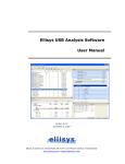
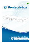
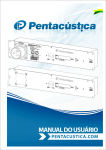
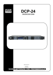
M12
PROFESSIONAL STAGE MONITOR
Operation Manual
Operation and Installation Manual
EC STATEMENT OF CONFORMITY
This document confirms that the range of products of Community Professional Loudspeakers bearing the CE
label meet all of the requirements in the EMC directive 89/336/EEC laid down by the Member States Council
for adjustment of legal requirements. Furthermore, the products comply with the rules and regulations
referring to the electromagnetic compatibility of devices from 30-August-1995.
The Community Professional Loudspeaker products bearing the CE label comply with the following
harmonized or national standards:
DIN EN 55013:08-1991
DIN EN 55020:05-1995
DIN EN 55082-1:03-1993
The authorized declaration and compatibility certification resides with the manufacturer and can be viewed
upon request. The responsible manufacturer is the company:
Community Light & Sound
333 East 5th Street
Chester, PA 19013
USA
TEL: 1-610 876-3400
FAX: 1-610 874-0190
Chester, PA USA December 2008
Community M12 – Installation / Operation Manual - Page 2
TABLE OF CONTENTS
IMPORTANT SAFETY INFORMATION .......................................................................... 4 UNPACKING AND INSPECTION .................................................................................. 4 INTRODUCTION ......................................................................................................... 5 FIGURE 1: M12 WITH THE GRILLE REMOVED.................................................................................. 5 FIGURE 2: M12 DISPERSION PATTERN......................................................................................... 6 OPTIONS AND ACCESSORIES ..................................................................................... 6 TABLE 1: M12 STANDARD MODELS AND ACCESSORIES .................................................................... 6 FIGURE 3: PORTABLE VERSION M12 WITH BUILT-IN ERGONOMIC SIDE HANDLES ....................................... 7 FIGURE 4: M12 SHOWN WITHOUT HANDLES .................................................................................. 7 FIGURE 5: INSTALL VERSION M12 WITH MATCHING COLOR MOUNTING PLATE FOR WALL OR CEILING
MOUNTING .......................................................................................................................... 7 PERFORMANCE MONITORING .................................................................................... 8 FIGURE 6: M12R WITH THE HF HORN MOLDED TO THE RIGHT OF THE LF DRIVER ...................................... 8 FIGURE 7: M12L WITH THE HF HORN MOLDED TO THE LEFT OF THE LF DRIVER ........................................ 8 FIGURE 8: M12 CABLE CLIPS ................................................................................................... 9 FIGURE 9: MULTIPLE M12'S RUNNING FROM THE SAME AMPLIFIER CHANNEL ............................................ 9 PERMANENT INSTALLATION .................................................................................... 10 FIGURE 10: M12 WALL/CEILING MOUNTING PLATE ........................................................................ 10 FIGURE 11: WALL MOUNT ASSEMBLY DIAGRAM ............................................................................ 10 FIGURE 12: CEILING MOUNT ASSEMBLY DIAGRAM ......................................................................... 11 DRAWINGS AND SPECIFICATIONS........................................................................... 12
TABLE 2: M12 SPECIFICATIONS .............................................................................................. 13 RECOMMENDED DSP SETTINGS ................................................................................ 14 WARRANTY INFORMATION AND SERVICE ................................................................ 14 TRANSFERABLE WARRANTY "(LIMITED)” VALID IN THE USA ONLY...................................................... 14 OBTAINING WARRANTY SERVICE ............................................................................................. 15 WARRANTY INFORMATION AND SERVICE FOR COUNTRIES OTHER THAN THE USA .................................... 15 Community M12 – Installation / Operation Manual - Page 3
IMPORTANT SAFETY INFORMATION
Always follow these basic safety precautions when using M12 loudspeakers and accessories:
1.
2.
3.
4.
5.
Read these instructions.
Keep these instructions.
Heed all warnings.
Follow all instructions, particularly those pertaining to rigging, mounting, hanging and electrical
connections.
Only use accessories that are specified and approved by the manufacturer.
The terms CAUTION, WARNING, and DANGER are used throughout this manual to alert the reader to
important safety considerations. If you have any questions or do not understand the meaning of these
terms, do not proceed with installation. Contact your local dealer, distributor, or call Community directly for
assistance. These terms are defined below:
CAUTION: describes an operating condition or user action that may expose the equipment
or user to potential damage or danger.
WARNING: describes an operating condition or user action that will likely cause damage to
the equipment or injury to the user or to others in the vicinity.
DANGER: describes an operating condition or user action that will immediately damage the
equipment and/or be extremely dangerous or life threatening to the user or to others in the
vicinity.
UNPACKING AND INSPECTION
The Community M12 loudspeaker is inherently rugged and packed in well-designed shipping cartons. It is
recommended that you carefully inspect the unit after removing it from the packaging to check for any
hidden damage due to possible shipping incidents.
CAUTION: When unpacking and handling an M12 be careful not to scratch or scrape the
black paint on the perforated metal grille. The finish on the grille protects the steel from
corrosion, and any scratches or scrapes that remove the finish leave the steel exposed to
corrosion.
Please note that once the shipment has left Community (or the dealer) the responsibility for damage is
borne by the freight company. If there is damage, you must file a claim directly with the freight company.
Each carrier has its own set of rules and regulations, with their own unique forms to fill out.
You are responsible for contacting the freight company immediately if you discover shipping damage. Save
the carton with all shipping materials in the event you need to ship the unit in order to avoid damage
claims being denied due to the lack of proper packaging. The Community dealer and the factory will try to
help in any way possible, however, please remember it is up to the party receiving the shipment to file the
claim.
The shipment is packed with the following:
(1) M12 loudspeaker
(1) Owner’s manual
(1) Warranty card
M12 install version also includes:
(1)
(4)
(4)
(4)
(4)
Mounting plate
2-inch diameter rubber washers
10mm (40mm length) hex head bolts
10mm flat washers
10mm lock washers
Community M12 – Installation / Operation Manual - Page 4
COMMUNITY M12 MANUAL
Thank you for purchasing the Community M12 monitor. We are confident you’ll agree it is an innovative
combination of performance monitor and permanent installation cabinet. We are gratified you have chosen
Community, and we will continue to do our best to live up to the reputation we have earned.
In order for you to get the most from your Community purchase, we recommend that you take a few
minutes and read this manual thoroughly. We have included a great deal of useful information to help you
get the best possible performance from the M12 monitor. After you have read the manual, please keep it
accessible so that you can refer to it easily.
This manual contains information for the proper setup and operation of the M12 loudspeaker, which can be
used as a professional stage monitor or permanently installed. Every effort has been made to insure that
the information contained in this manual was complete and accurate at the time of printing. However, due
to ongoing technical advances, changes or modifications may have occurred that are not covered in this
manual.
INTRODUCTION
The Community M12 is a two-way, full-range, bass-ported performance loudspeaker. Its low profile exterior
occupies a very small footprint, making it an ideal choice for stage monitors. The rugged multilayer glass
composite construction, stainless steel grille and an abrasion-resistant non-reflective finish make the M12 an
excellent choice for high ambient light scenarios, such as TV broadcasts and live stage events. Specially
molded channels and cable clips allow speaker cables to be routed through the sides and the bottom of the
enclosure, and the dual Neutrik NL4 connectors are tucked safely away in a pocket beneath the enclosure.
The M12 features a high-powered 12-inch woofer and a 2-inch exit wide-band high frequency driver, which
are mounted to a molded one-piece asymmetrical horn with a 90-degree dispersal pattern at the top and
40-degree dispersal pattern at the bottom. This unique horn design allows the M12 to operate at full-range
output and be equally effective up close or at a distance. The M12 can be ordered with the HF horn
mounted either to the left or right of the woofer, allowing for mirrored pairs.
The M12 offers numerous features and advances in technology. Some of these include:
•
•
•
•
•
•
•
•
•
•
•
Low profile design, high style exterior with small footprint
Unique asymmetrical 40° – 90° x 70° coverage pattern
Multilayer glass composite construction
Ergonomic rubber pocket grip handles
Non-reflective exterior with matching heavy-duty non-reflective grille
High powered, 12-inch woofer
2-inch exit wide-band compression driver on an asymmetrical horn
Switchable bi-amp/passive configuration with well protected dual NL4 connectors
Available in black or white finishes, with mirror right or left horn configurations
Optional installation models available with M10 hang points and wall/ceiling mounting plate included
Five-year warranty
Figure 1: M12 with the grille removed
Community M12 – Installation / Operation Manual - Page 5
NOTE: The high frequency driver is mounted to a molded one-piece asymmetrical horn
with a 90-degree pattern at the top and 40 degree at the bottom, allowing full-range monitor
output close up or at a distance, as depicted in Figure 2.
Figure 2: M12 dispersion pattern
The M12 is designed primarily as a performance monitor placed on the stage. Its low profile design makes
it suitable for a wide range of stage monitoring situations, including music concerts, TV broadcasts and live
theater events. Ergonomic rubber pocket grip handles on the portable model makes the M12 easy to lift
and easy to transport. In addition to traditional stage monitoring, the M12 may also be permanently
installed on a wall or ceiling and/or used as part of a main FOH (front-of-house) sound system in houses of
worship, conference centers, auditoria, lecture halls, and mounted under balconies for theaters.
OPTIONS AND ACCESSORIES
The M12 can be customized for any application using the multiple option combinations detailed below:
•
•
•
•
•
•
"R" suffix = HF horn molded to the "right" of the LF driver
"L" suffix = HF horn molded to the "left" of the LF driver
"B" suffix = "Black" paint finish with black grille and hardware
"W" suffix = "White" paint finish with white grille and hardware
"I" suffix = "Installation" version with four M10 hang points and mounting bracket
"P" suffix = "Portable" version with built-in ergonomic handles
Road cases for two and four M12 monitors are available as optional accessories.
Table 1 lists a summary of the available M12 models and accessories.
Table 1: M12 Standard Models and Accessories
Part Number
Description
M12R-BP
Portable version M12 with the HF horn molded into the faceplate to the right of
the LF driver, black finish, two handles.
M12R-WP
Portable version M12 with the HF horn molded into the faceplate to the right of
the LF driver, white finish, two handles.
M12R-BI
Install version M12 with the HF horn molded into the faceplate to the right of the
LF driver, four M10 hang points, black finish and matching black wall/ceiling
mounting plate included, no handles.
M12R-WI
Install version M12 with the HF horn molded into the faceplate to the right of the
LF driver, four M10 hang points, white finish and matching white wall/ceiling
mounting plate included, no handles.
M12L-BP
Portable version M12 with the HF horn molded into the faceplate to the left of
the LF driver, black finish, two handles.
M12L-WP
Portable version M12 with the HF horn molded into the faceplate to the left of
the LF driver, white finish, two handles.
Community M12 – Installation / Operation Manual - Page 6
M12L-BI
Install version M12 with the HF horn molded into the faceplate to the left of the
LF driver, four M10 hang points, black finish and matching black wall/ceiling
mounting plate included, no handles.
M12L-WI
Install version M12 with the HF horn molded into the faceplate to the left of the
LF driver, four M10 hang points, white finish and matching white wall/ceiling
mounting plate included, no handles.
M12-RDCASE2
Black ATA Case to hold two single M12 stage monitors with four recessed
latches, eight recessed handles, accessory compartment and 4-inch casters
(30”H x 30”W x 30” D).
M12-RDCASE4
Black ATA Case to hold four single M12 stage monitors with four recessed
latches, eight recessed handles, accessory compartment and 4-inch casters
(30.5"H x 47.5"W x 30"D).
NOTE: Standard portable versions of the M12 include built-in handles, while install versions include
mounting points and a wall/ceiling mounting plate. The M12 monitor may also be custom ordered in any
variety with or without handles and/or mounting points. Please contact the factory for more information.
Figure 3: Portable version M12 with built-in ergonomic side handles
Figure 4: M12 shown without handles
Figure 5: Install version M12 with matching color
mounting plate for wall or ceiling mounting
Community M12 – Installation / Operation Manual - Page 7
PERFORMANCE MONITORING
Place the M12 on a flat surface. For full-range operation, connect the M12 to one channel of a power
amplifier (600W-900W per channel @ 8 ohms), using an appropriate cable wired with a Neutrik NL4
connector. Ensure that the switch on the underside of the M12 labeled “Bi-amp/Passive” is placed in the
“Passive” position. For bi-amp operation, one Neutrik Speakon input receives the HF output from an
appropriate power amplifier (130W/160W @ 8 ohms) and one Neutrik Speakon input receives the LF input
from an appropriate power amplifier (600W/900W per channel @ 8 ohms). In bi-amp mode, in order to
prevent possible damage to the HF element, an electronic crossover, analog or digital, must be used ahead
of the power amplifier channels. Set the electronic crossover frequency to 1.5 kHz to match the built-in
crossover provided for passive operation. Ensure that the switch on the underside of the M12 labeled “Biamp/Passive” is placed in the “Bi-amp” position. For both passive and bi-amp operation, turn each
amplifier channel up to a comfortable listening level.
CAUTION: Operating the M12 at an excessive volume level can cause hearing damage
and/or permanent hearing loss.
Figures 6 and 7 depict the optional left and right HF configurations of the M12. This configuration choice
allows the M12 to be placed virtually anywhere around the performer.
Figure 6: M12R with the HF horn molded to the right of the LF driver
Figure 7: M12L with the HF horn molded to the left of the LF driver
The M12 is provided with cable channels on the back and side of the loudspeaker, along with clips located
on the bottom of the loudspeaker to neatly hold speaker cables, providing a safe and secure cable route to
the locking Neutrik NL4 connectors. This combination of routing and clips allows the loudspeaker to rest
flat on the floor for a lower profile on stage.
Community M12 – Installation / Operation Manual - Page 8
Figure 8: M12 Cable Clips
The M12 loudspeaker can be configured in multiples running from the same amplifier channel. When
connecting multiple M12’s to the same amplifier channel, connect the first M12 directly from the amplifier,
using 2-conductor, rubber-jacketed loudspeaker cable, with a Neutrik NL4 connector. Each M12 has two
(2) NL4 jacks. Connect the second M12 to the first by “daisy-chaining” it to the first M12. Since the M12 is
a nominal 8-ohm loudspeaker, connecting two (2) in this way creates a 4-ohm load across the amplifier, as
shown in the top part of Figure 9. If desired, a third M12 can be added the same way, as shown in the
lower part of Figure 9. For best results, use either 14 AWG or 12 AWG loudspeaker cable.
Figure 9: Multiple M12's running from the same amplifier channel
CAUTION: Adding a third M12, as shown in Figure 9, will create a 2-ohm load on the
amplifier. Please refer to the owner’s manual of the amplifier before connecting a third
M12 to ensure that the amplifier will support 2-ohm operation.
Community M12 – Installation / Operation Manual - Page 9
PERMANENT INSTALLATION
The install version of the M12 can be used anywhere a conventional 12-inch two-way loudspeaker would be
used. It can also be used in many applications where a conventional loudspeaker would not be appropriate,
such as overhead or under-balcony in a theater, conference rooms and distributed systems. The M12
install version is provided with a mounting bracket plate and four M10 hanging points. Connect the
mounting bracket to the M12 using the four provided 40mm hex bolts, 10mm lock washers and 10mm flat
washers. The entire assembly can then be mounted to a flat surface. The OmniMount bolt pattern on the
back of the bracket is drilled out at the center of gravity for safe and secure mounting.
Figure 10: M12 wall/ceiling mounting plate
Note: (1) OmniMount 120 bolt pattern is located at the center of gravity.
No hardware is provided to attach the M12 and bracket assembly to the mounting surface. Such hardware
must be supplied by the installer and should be sized and rated for the weight load of the enclosure. The
installer is solely responsible for determining if all rigging components that are used to mount or suspend
the enclosure are adequately sized and rated, and if the structure they are mounted or suspended from is
capable of safely supporting the aggregate weight load. It is always the installer’s responsibility to insure
that the combined weight load does not exceed the Working Load Limit of any one rigging fitting.
Figure 11: Wall mount assembly diagram
(4) M10 x 40mmHEX BOLT
(4) 10mm LOCK WASHER
(4) 10mm FLAT WASHER
Community M12 – Installation / Operation Manual - Page 10
Figure 12: Ceiling mount assembly diagram
(4) M10 x 40mm
HEXBOLT
(4) 10mm LOCK WASHER
(4) 10mm FLAT WASHER
WARNING: The bolts used and wall material into which the M12 and mounting
plate assembly is bolted must be capable of supporting the load of the enclosure
to be mounted. It is the responsibility of the installer to verify these items.
CAUTION: Installation of loudspeakers should only be performed by trained and
qualified personnel. It is strongly recommended that a licensed and certified
professional structural engineer approve the mounting design.
Community M12 – Installation / Operation Manual - Page 11
DRAWINGS AND SPECIFICATIONS
Figure 13: Portable version M12 dimensional drawing
21.500" [546.1]
20.750" [527.05]
10.500"[266.70]
TOP
VIEW
TOP
SIDE VIEW
FRONT
VIEW
FRONT
Figure 14: Install version M12 dimensional drawing
21.500" [546.1]
20.750" [527.05]
FRONT
FRONT
VIEW
TOPTOP
VIEW
CL
5.813" [147.64]
M10 HANG
POINT
(2) M10
HANG POINT
10.500" [266.70]
2.750" [69.85]
17.250" [438.15]
RIGHT SIDE
RIGHT
M10 HANG POINT
2.750"
[69.85]
11.625" [295.28]
REARVIEW
REAR
LEFT
SIDE
LEFT
Community M12 – Installation / Operation Manual - Page 12
Table 2: M12 Specifications
Loudspeaker Type:
Two-way, full-range, bass ported stage monitor
Operating Range:
55 Hz to 18 kHz
80 Hz to 16 kHz (±2 dB)
Nominal -6dB
Beamwidth:
40-90° H x 70° V
Axial Q / DI:
7.1 / 8.5, 1.5 kHz to 12.5 kHz
Recommended Signal
Processing:
60 Hz high pass filter
Drivers:
LF 1 x 12" Ferrofluid-cooled
HF 1 x 2" exit B&C DE85
Driver Protection:
None
Input Connection:
(2) Neutrik NL4MP
Controls:
Bi-amp/Passive switch
Enclosure:
Multilayer glass composite
Grille:
18-gauge perforated steel
Required Accessories:
DSP for bi-amp operation
Optional Accessories:
M12-RDCASE2 roadcase for two M12 monitors
M12-RDCASE4 roadcase for four M12 monitors
Height:
10.5 inches (266.7 mm)
Width:
21.5 inches (546.1 mm) - widest point
Depth:
20.75 inches (527.1 mm)
Weight:
56 lbs (25.4 kg)
Passive Mode
Bi-amp Mode
Max Input:
300W continuous, 750W program
49 volts RMS,
110 volts momentary peak
LF - same as for passive mode
HF - 80W continuous, 160W program
25 volts RMS,
51 volts momentary peak
Recommended Power
Amplifier:
630W to 900W @ 8 ohms
LF - same as for passive mode
HF - 130W to 190W @ 8 ohms
Sensitivity (1W/1m):
97 dB SPL (100 Hz to 16 kHz 1/3
octave bands)
98 dB SPL (250 Hz to 4 kHz speech
range)
LF - 99 dB SPL (100 Hz to 1600 Hz 1/3
octave bands)
HF - 106 dB SPL (2 kHz to 16 kHz 1/3
octave bands)
Maximum Output:
122 dB SPL / 129 dB SPL (peak)
124 dB SPL / 131 dB SPL (peak)
Nominal Impedance:
8 ohms
LF - 8 ohms
HF - 8 ohms
Minimum Impedance:
5.3 ohms @ 1.9 kHz
N/A
Crossover Frequency:
N/A
1.5 kHz
Community M12 – Installation / Operation Manual - Page 13
RECOMMENDED DSP SETTINGS
M12 Bi-amp (LF)
High-Pass Filter: Butterworth 24 dB / Oct, 50 Hz (Varies based on the full-range system used)
Low-Pass Filter: Butterworth 24 dB / Oct, 1560 Hz (Varies based on the full-range system used)
Filter Type
Frequency
Gain
Q
PEQ1
116 Hz
+3 dB
2.4 Oct
PEQ2
480 Hz
-6 dB
5 Oct
PEQ3
800 Hz
-3 dB
5.5 Oct
PEQ4
1280 Hz
+3 dB
2 Oct
M12 Bi-amp (HF)
High-Pass Filter: Butterworth 24 dB / Oct, 1520 Hz (Varies based on the full-range system used)
Delay 167us
Filter Type
Frequency
Gain
Q
PEQ1
2800 Hz
-3 dB
2 Oct
PEQ2
4300 Hz
+2 dB
1.6 Oct
PEQ3
10.8 kHz
-3 dB
0.33 Oct
M12 Passive
High-Pass Filter: Butterworth 24 dB / Oct, 50 Hz (Varies based on the full-range system used)
Filter Type
Frequency
Gain
Q
PEQ1
2800 Hz
-3 dB
2 Oct
PEQ2
4300 Hz
+2 dB
1.6 Oct
PEQ3
10.8 kHz
-3 dB
0.33 Oct
____________________________________________________________________________________________
WARRANTY INFORMATION AND SERVICE
Transferable Warranty "(Limited)” Valid in the USA Only
Community M12 monitor loudspeakers are warranted in the USA to be free from manufacturing defects in
materials and workmanship for a period of five years, as determined by one of the following two methods,
whichever is longer:
Starting from the date of retail purchase, as noted on the sales receipt from an authorized Community
dealer,
OR
Starting from the date of manufacture, determined by the serial number, if the sales receipt is not available.
This warranty applies to the product; therefore, the remainder of the warranty period will be automatically
transferred to any subsequent owner.
This warranty applies only to failure of a Community loudspeaker caused by defects in materials and
workmanship during the stated warranty period. It does not apply to a unit that has been subjected to
abuse, accident, modification, improper handling/installation, or repairs made without factory authorization
or by anyone other than authorized Community Field Service Stations. This warranty is void if the serial
number has been defaced, altered or removed.
Products covered by this warranty will be repaired or replaced at the option of Community, without charge
for materials or labor, provided all the terms of this warranty have been met.
Community M12 – Installation / Operation Manual - Page 14
Obtaining Warranty Service
Warranty service may be obtained from the factory, or from an authorized Field Service Station.
To obtain factory or field warranty service for products purchased in the United States, return the product
for inspection to the address below, freight prepaid, in the original packaging. If the original packaging is
not available, call or write Community Warranty Service to obtain proper packaging materials or hand carry
the product to the nearest Field Service Station.
Factory Service Center:
Community Warranty Service
333 East Fifth Street
Chester, PA 19013-4511 USA
Field Service Station:
Call (610) 876-3400 for the nearest Authorized Field Service Station
For factory service, please call (610) 876-3400 for a Return Authorization (R/A) number before shipping.
The following information must be included in the package:
1)
Owner’s complete name, daytime phone number, return street address and return authorization
number.
2)
The serial number of the product being returned and a copy of the retail sales receipt, if possible.
3)
A complete description of the problem(s) experienced, including a brief description of how the
equipment is being used and with what brand, model and output power of amplifier.
Upon receipt, the service center will determine if the problem is covered under warranty. If covered under
this warranty, the product will be repaired or replaced, at Community’s option, and returned to the owner
freight prepaid. If the problem is not covered under this warranty, the owner will be notified of the problem
with an estimate of the repair costs.
Consequential and Incidental Damages: Community shall not be liable for any consequential or incidental
damages including, without limitation, injury to persons, property, or loss of use. Some states do not allow
the exclusion or limitations of consequential or incidental damages, so the above limitations and exclusions
may not apply.
This Community warranty is not extended by the length of time which an owner is deprived of the use of the
product. Repairs and replacement parts provided under the terms of this warranty shall carry only the
remaining portion of the warranty.
Community reserves the right to change the design of any product from time to time, without notice and
with no obligation to make corresponding changes in products previously manufactured.
While this warranty gives specific legal rights, there may also be other rights that vary from state to state.
No action to enforce this warranty shall be permitted ninety days after expiration of the warranty period.
Warranty Information and Service for Countries Other Than the USA
To obtain specific warranty information and available service locations for countries other than the United
States of America, contact the authorized Community Distributor for your specific country or region.
Community M12 – Installation / Operation Manual - Page 15
Community Professional Loudspeakers
333 East Fifth Street, Chester, PA 19013-4511 USA
Tel: 1-(610) 876-3400 | Fax: 1-(610)874-0190
www.communitypro.com
© 2008 All Rights Reserved
20081222