1
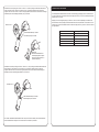
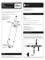
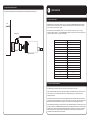
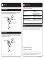
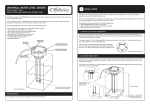
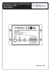
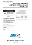
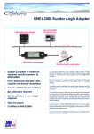
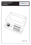
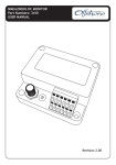
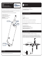
HYDROSTATIC SIDE MOUNT TANK LEVEL
SENDER
1
Part Number: 4272-1, 4272-2, 4272-3
INSTALLATION AND OPERATING INSTRUCTIONS
You will find the following items in the 4272 package:
The Offshore Systems 4272 NMEA2000 Hydrostatic Side Mount Tank Level Sender measures the level of a Fuel tank.
It is very important that it is installed and set up correctly according to this manual. Please read and follow the
installation and setup instructions carefully to achieve the best results.
The 4272 NMEA2000 Hydrostatic Side Mount Tank Level Sender has the following features:
•
•
•
•
•
•
1 x 4272 NMEA2000 Hydrostatic Side Mount Tank Level Sender
1 x 4272 User Manual (This document)
1.1 MOUNTING LOCATION AND REQUIREMENTS
Level sensing from 0.5 to 4 metres
User settable for tank Level or tank Volume output
User settable tank instance from 0 to 15
Heartbeat blue LED to indicate normal activity
NMEA2000 Interface
Stainless Steel 303 sensor face plate
Blue LED Indicator
INSTALLATION
Requirements:
• Silicone grease
• 34mm spanner or adjustable spanner
• PTFE Tape
Tank Instance
This unit must be mounted in an area protected from water and physical damage.
It is available as a number of thread fittings, such as ¼” BSP, M12 and J1926-1-4.
Calibration
Push Button
The sender is designed to be mounted in the side, at the bottom of the fuel tank into a threaded fitting. The tank
must have this fitting installed.
• Apply silicone grease to the o-ring.
• Apply PTFE tape to thread on end of sensor body.
• Insert the sensor by hand, being careful not to cross-thread.
• Make sure the area around o-ring is clean
• Hand tighten and then use spanner to further tighten ½ turn.
1.2 CONNECTING THE NMEA2000 INTERFACE
The unit must be connected to the NMEA2000 bus with POWER OFF to prevent damage.
The NMEA2000 interface cable on the unit should be connected to a nearby NMEA2000 Tee connector (part
number 3802). The male end of the cable should be inserted into the female Tee connection noting the position of
the keyway in the plug and the socket. This cable can be extended up to a maximum length of 6 metres to the
Tee connector. Ensure that the locking ring is securely tightened so that the connection is waterproof and secure.
To display
NMEA2000 Network Backbone
¼” BSP, M12 and
J1926-1-4 Mount.
3804 Male
Terminator
3802 T - Adaptor
+12v
FIRMWARE REVISION
The information in this manual corresponds to firmware revision v1.0
Connect
to Tank
1.3 SUGGESTED MOUNTING METHOD
It is highly recommended that the Tank and Hydrostatic Sender is separated by an isolating valve.
2
CONFIGURATION
2.2 TANK DEVICE INSTANCE
Tank
NMEA2000 requires a unique Device Instance to be set for each type of 4272 NMEA2000 Hydrostatic Side Mount
Tank Level Sender on a single network. This is settable from device instance 0 to Device Instance 15 using the
small rotary switch on the top of the sender.
This can be set at any time regardless if power is on or off. The switch counts from 0 – 9 then A – F being
equivalent to Device Instance 0 – 15. The NMEA2000 Device Instance is set by using the small rotary switch on the
front panel labeled “Tank No.” as per the following table:
Isolating Valve
Switch Position
Device Instance
0
0
1
1
2
2
3
3
4
4
5
5
6
6
7
7
8
8
Hydrostatic Sender
9
9
A
10
B
11
C
12
D
13
E
14
F
15
2.2 OUTPUT MODE CONFIGURATION
The 4272 Hydrostatic Side Mount Tank Level Sender has two output modes to choose from.
It has a normal tank LEVEL output from 0 – 100% that indicates the exact LEVEL of the fluid in the tank. The user
can tell when the unit is in Level Mode because the blue LED flashes ONCE every 2.5 seconds when a level
message has been sent.
In addition to this mode the unit can transmit a tank VOLUME output from 0-100% that reflects the actual fluid
volume within the tank taking allowance for the tanks internal shape. The user can tell when the unit is in Volume
Mode because the blue LED flashes twice rapidly every 2.5 seconds when a volume message has been sent.
The Volume Mode PGN message is exactly the same as the Level Mode PGN message which means that the volume
can easily be shown on any NMEA2000 display that accepts Fluid Level PGNs from tank senders. The Volume Mode
Tank data can be entered from any Offshore Systems Display that is equipped to set up this data (e.g. 3340 and
3350). Please contact us for more information on these displays. It can also be set up at manufacture if the
information is made available at the time of ordering.
Level Mode can be set by setting the “Tank No.” switch to “C” and then pressing the Calibration Push Button for
at least 5 seconds. The blue LED will turn on and stay on for 2.5 seconds to indicate that the unit has been
configured. Then return the “Tank No.” switch to its original position and the sender will transmit Level messages
as indicated by the blue LED flashing ONCE briefly every 2.5 seconds.
23456
789
Push Calibration Button for 5 seconds
Blue LED stays on for 2.5 seconds
Please note:
The Push Calibration Button is
recessed slightly and will require
the use of a small screwdriver to
press the button fully.
Volume Mode can be set by setting the “Tank No.” switch to “D”, then pressing the Calibration Push Button for at
least 5 seconds. The blue LED will turn on and stay on for 2.5 seconds to indicate that the unit has been
configured. When the switch is returned to its original position the sender will transmit Volume messages as
indicated by the blue LED flashing rapidly TWICE every 2.5 seconds.
23456
F01
ABCDE
Tank No. set to ‘D’
The 4272 Hydrostatic Side Mount Tank Level Sender achieves damping by averaging tank level values measured
over a set period of time. This period of time can be configured to be 5, 10, 15, 20 or 25 seconds. By default the
damping is set to 15 seconds.
Damping Level can be changed by setting the “Tank No.” switch to a value corresponding to the desired level
(see table below) and then pressing the Calibration Push Button for at least 5 seconds. The blue LED will turn on
and stay on for 2.5 seconds to indicate that the unit has been configured. Finally, return the “Tank No.” switch to
its original position.
F01
ABCDE
Tank No. set to ‘C’
2.3 DAMPING LEVEL CONFIGURATION
789
Push Calibration Button for 5 seconds
Blue LED stays on for 2.5 seconds
If the sender’s Volume Mode Tank Data has NOT been set up and the unit is accidently set to Volume Mode then
the data transmitted will actually be the Level Data so the unit remains fully functional.
Switch Position
Damping Level (seconds)
7
5
8
10
9
15
A
20
B
25
3
4
CALIBRATION
TROUBLESHOOTING
When the unit is first installed it needs to be calibrated to the tank. This is easily done as follows:
The following table will help diagnose common faults:
3.1 TANK EMPTY CALIBRATION
When the unit is first installed in an EMPTY tank and powered on, the Tank Empty Calibration is done by setting
the “Tank No.” switch to “E”, then pressing the Calibration Push Button for at least 5 seconds. The blue LED will
turn on and stay on for 2.5 seconds to indicate that the empty calibration is complete.
23456
F01
ABCDE
Tank No. set to ‘E’
LED does not flash
Check power on network
LED flashes rapidly
Network not terminated correctly or no other
NMEA2000 device on the network
LED flashes once every 2.5 seconds
Normal Operation in Level mode (see 2.2 above)
LED Flashes twice every 2.5 seconds
Normal Operation in Volume mode (see 2.2 above)
LED on for about 2.5 seconds
Configuration or calibration has been successful
789
Push Calibration Button for 5 seconds
Blue LED stays on for 2.5 seconds
MAINTENANCE
Ensure that the sender is mounted securely to the tank and that there are no liquid leaks. Reseat and tighten if
necessary. Check the security of the NMEA2000 cable to the NMEA2000 Tee Connector and tighten if necessary.
Clean the unit with a damp soft cloth. Do not use chemical cleaners as they may remove label markings.
3.2 TANK FULL CALIBRATION
This is easily done in a FULL tank and powered on by setting the “Tank No.” switch to “F”, then pressing the
Calibration Push Button for at least 5 seconds. The blue LED will turn on and stay on for 2.5 seconds to indicate
that the fixed full calibration point has been set.
23456
F01
ABCDE
Tank No. set to ‘F’
789
Push Calibration Button for 5 seconds
Blue LED stays on for 2.5 seconds
Offshore Systems (UK) Ltd
Unit 10 -11 Milton Business Centre, Wick Drive,
New Milton, Hampshire, BH25 6RH, United Kingdom
Tel: +44(0)1425 610022
Email: [email protected]
In all cases do not forget to set the “Tank No.” switch back to its original tank number.
Fax: +44(0)1425 614794
Web: www.osukl.com
Copyright © 2013 Offshore Systems (UK) Ltd. All rights reserved.Our policy is one of continuous product improvement so product
specifications are subject to change without notice. Offshore Systems products are designed to be accurate and reliable. However,
they should be used only as aids to vessel monitoring, and not as a replacement for traditional navigation and vessel monitoring
techniques. NMEA2000® is a registered trademark of the National Marine Electronics Association.
DOC NO. 00120 v1.0
HYDROSTATIC SIDE MOUNT TANK LEVEL
SENDER
1
Part Number: 4282
INSTALLATION AND OPERATING INSTRUCTIONS
INSTALLATION
You will find the following items in the 4282 package:
The Offshore Systems 4282 NMEA2000 Hydrostatic Side Mount Tank Level Sender measures the level of a Water
tank.
1 x 4282 NMEA2000 Hydrostatic Side Mount Tank Level Sender
1 x 4282 User Manual (This document)
It is very important that it is installed and set up correctly according to this manual. Please read and follow the
installation and setup instructions carefully to achieve the best results.
1.1 MOUNTING LOCATION AND REQUIREMENTS
The 4282 NMEA2000 Hydrostatic Side Mount Tank Level Sender has the following features:
•
•
•
•
•
•
Level sensing from 0.5 to 4 metres
User settable for tank Level or tank Volume output
User settable tank instance from 0 to 15
Heartbeat blue LED to indicate normal activity
NMEA2000 Interface
Stainless Steel 303 sensor face plate
Blue LED Indicator
Requirements:
• Silicone grease
• 34mm spanner or adjustable spanner
• PTFE Tape
Tank Instance
This unit must be mounted in an area protected from water and physical damage.
It is available as a number of thread fittings, such as ¼” BSP, M12 and J1926-1-4.
Calibration
Push Button
The sender is designed to be mounted in the side, at the bottom of the water tank into a threaded fitting. The
tank must have this fitting installed.
• Apply silicone grease to the o-ring.
• Apply PTFE tape to thread on end of sensor body.
• Insert the sensor by hand, being careful not to cross-thread.
• Make sure the area around o-ring is clean
• Hand tighten and then use spanner to further tighten ½ turn.
1.2 CONNECTING THE NMEA2000 INTERFACE
The unit must be connected to the NMEA2000 bus with POWER OFF to prevent damage.
The NMEA2000 interface cable on the unit should be connected to a nearby NMEA2000 Tee connector (part
number 3802). The male end of the cable should be inserted into the female Tee connection noting the position of
the keyway in the plug and the socket. This cable can be extended up to a maximum length of 6 metres to the
Tee connector. Ensure that the locking ring is securely tightened so that the connection is waterproof and secure.
To display
NMEA2000 Network Backbone
¼” BSP, M12 and
J1926-1-4 Mount.
3804 Male
Terminator
3802 T - Adaptor
+12v
FIRMWARE REVISION
The information in this manual corresponds to firmware revision v1.00.0
Connect
to Tank
1.3 SUGGESTED MOUNTING METHOD
It is highly recommended that the Tank and Hydrostatic Sender is separated by an isolating valve.
2
CONFIGURATION
2.2 TANK DEVICE INSTANCE
Tank
NMEA2000 requires a unique Device Instance to be set for each type of 4282 NMEA2000 Hydrostatic Side Mount
Tank Level Sender on a single network. This is settable from device instance 0 to Device Instance 15 using the
small rotary switch on the top of the sender.
This can be set at any time regardless if power is on or off. The switch counts from 0 – 9 then A – F being
equivalent to Device Instance 0 – 15. The NMEA2000 Device Instance is set by using the small rotary switch on the
front panel labeled “Tank No.” as per the following table:
Isolating Valve
Switch Position
Device Instance
0
0
1
1
2
2
3
3
4
4
5
5
6
6
7
7
8
8
Hydrostatic Sender
9
9
A
10
B
11
C
12
D
13
E
14
F
15
2.2 OUTPUT MODE CONFIGURATION
The 4282 Hydrostatic Side Mount Tank Level Sender has two output modes to choose from.
It has a normal tank LEVEL output from 0 – 100% that indicates the exact LEVEL of the fluid in the tank. The user
can tell when the unit is in Level Mode because the blue LED flashes ONCE every 2.5 seconds when a level
message has been sent.
In addition to this mode the unit can transmit a tank VOLUME output from 0-100% that reflects the actual fluid
volume within the tank taking allowance for the tanks internal shape. The user can tell when the unit is in Volume
Mode because the blue LED flashes twice rapidly every 2.5 seconds when a volume message has been sent.
The Volume Mode PGN message is exactly the same as the Level Mode PGN message which means that the volume
can easily be shown on any NMEA2000 display that accepts Fluid Level PGNs from tank senders. The Volume Mode
Tank data can be entered from any Offshore Systems Display that is equipped to set up this data (e.g. 3340 and
3350). Please contact us for more information on these displays. It can also be set up at manufacture if the
information is made available at the time of ordering.
Level Mode can be set by setting the “Tank No.” switch to “C” and then pressing the Calibration Push Button for
at least 5 seconds. The blue LED will turn on and stay on for 2.5 seconds to indicate that the unit has been
configured. Then return the “Tank No.” switch to its original position and the sender will transmit Level messages
as indicated by the blue LED flashing ONCE briefly every 2.5 seconds.
23456
789
Push Calibration Button for 5 seconds
Blue LED stays on for 2.5 seconds
Please note:
The Push Calibration Button is
recessed slightly and will require
the use of a small screwdriver to
press the button fully.
Volume Mode can be set by setting the “Tank No.” switch to “D”, then pressing the Calibration Push Button for at
least 5 seconds. The blue LED will turn on and stay on for 2.5 seconds to indicate that the unit has been
configured. When the switch is returned to its original position the sender will transmit Volume messages as
indicated by the blue LED flashing rapidly TWICE every 2.5 seconds.
23456
F01
ABCDE
Tank No. set to ‘D’
The 4282 Hydrostatic Side Mount Tank Level Sender achieves damping by averaging tank level values measured
over a set period of time. This period of time can be configured to be 5, 10, 15, 20 or 25 seconds. By default the
damping is set to 15 seconds.
Damping Level can be changed by setting the “Tank No.” switch to a value corresponding to the desired level
(see table below) and then pressing the Calibration Push Button for at least 5 seconds. The blue LED will turn on
and stay on for 2.5 seconds to indicate that the unit has been configured. Finally, return the “Tank No.” switch to
its original position.
F01
ABCDE
Tank No. set to ‘C’
2.3 DAMPING LEVEL CONFIGURATION
789
Push Calibration Button for 5 seconds
Blue LED stays on for 2.5 seconds
If the sender’s Volume Mode Tank Data has NOT been set up and the unit is accidently set to Volume Mode then
the data transmitted will actually be the Level Data so the unit remains fully functional.
Switch Position
Damping Level (seconds)
7
5
8
10
9
15
A
20
B
25
3
4
CALIBRATION
TROUBLESHOOTING
When the unit is first installed it needs to be calibrated to the tank. This is easily done as follows:
The following table will help diagnose common faults:
3.1 TANK EMPTY CALIBRATION
When the unit is first installed in an EMPTY tank and powered on, the Tank Empty Calibration is done by setting
the “Tank No.” switch to “E”, then pressing the Calibration Push Button for at least 5 seconds. The blue LED will
turn on and stay on for 2.5 seconds to indicate that the empty calibration is complete.
23456
F01
ABCDE
Tank No. set to ‘E’
LED does not flash
Check power on network
LED flashes rapidly
Network not terminated correctly or no other
NMEA2000 device on the network
LED flashes once every 2.5 seconds
Normal Operation in Level mode (see 2.2 above)
LED Flashes twice every 2.5 seconds
Normal Operation in Volume mode (see 2.2 above)
LED on for about 2.5 seconds
Configuration or calibration has been successful
789
Push Calibration Button for 5 seconds
Blue LED stays on for 2.5 seconds
MAINTENANCE
Ensure that the sender is mounted securely to the tank and that there are no liquid leaks. Reseat and tighten if
necessary. Check the security of the NMEA2000 cable to the NMEA2000 Tee Connector and tighten if necessary.
Clean the unit with a damp soft cloth. Do not use chemical cleaners as they may remove label markings.
3.2 TANK FULL CALIBRATION
This is easily done in a FULL tank and powered on by setting the “Tank No.” switch to “F”, then pressing the
Calibration Push Button for at least 5 seconds. The blue LED will turn on and stay on for 2.5 seconds to indicate
that the fixed full calibration point has been set.
23456
F01
ABCDE
Tank No. set to ‘F’
789
Push Calibration Button for 5 seconds
Blue LED stays on for 2.5 seconds
Offshore Systems (UK) Ltd
Unit 10 -11 Milton Business Centre, Wick Drive,
New Milton, Hampshire, BH25 6RH, United Kingdom
Tel: +44(0)1425 610022
Email: [email protected]
In all cases do not forget to set the “Tank No.” switch back to its original tank number.
Fax: +44(0)1425 614794
Web: www.osukl.com
Copyright © 2013 Offshore Systems (UK) Ltd. All rights reserved.Our policy is one of continuous product improvement so product
specifications are subject to change without notice. Offshore Systems products are designed to be accurate and reliable. However,
they should be used only as aids to vessel monitoring, and not as a replacement for traditional navigation and vessel monitoring
techniques. NMEA2000® is a registered trademark of the National Marine Electronics Association.
DOC NO. 00120 v1.0