1
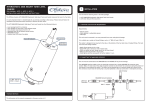
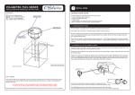
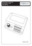
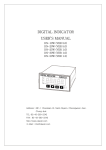
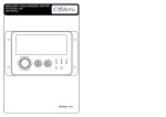
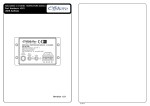
UNIVERSAL WATER LEVEL SENDER
1
Part Numbers: 3281
INSTALLATION AND OPERATING INSTRUCTIONS
The Offshore Systems 3281 NMEA2000 Universal Water Level Sender measures the level of either Fresh water, Grey
water or Black water tanks.
It is very important that it is installed and set up correctly according to this manual. Please read and follow the
installation and setup instructions carefully to achieve the best results.
The 3281 NMEA2000 Universal Water Sender has the following features:
•
•
•
•
•
•
•
•
User settable for Fresh Water, Grey Water or Black Water sensing
Water level sensing from 250mm to 2 metres
User settable for tank Level or tank Volume output
User settable tank instance from 0 to 15
Heartbeat blue LED to indicate normal activity
Red Warning LED to indicate damaged rods.
1.25” BSP single threaded mount
NMEA2000 Interface
INSTALLATION
Take great care when unpacking the sender that the coated rod is not damaged in any way. If the coating is
scraped or punctured the sender will not work.
We test every sender before it is packed so the coated rod is protected against transit damage. Do not remove the
protective packaging until you are ready to install the sender.
You should find the following items in the 3281 shipping tube:
1 x 3281 NMEA2000 Universal Water Level Sender
1 x Water Sender Probe End Cap (May already be attached)
1 x 3281 User Manual (This document)
1.1 MOUNTING LOCATION AND REQUIREMENTS
The sender is designed to be mounted on a flat area on the top of the water tank over the tank’s deepest part.
Examine the tank internal structure and choose a location that ensures the sender probes will not chafe on any of
the tank’s internal structure or baffles.
The sender requires a 1.25 inch standard BSP threaded mounting hole with a small 45° machine chamfer at the
top to seal against the sender mounting O ring.
Tank Type
Tank No.
Blue LED Indicator
If the tank has an existing SAE 5 bolt hole then the optional
3261 Mounting ring can be attached to the SAE 5 bolt holes to
provide a 1.25” BSP threaded hole mount for the Water Sender.
Red LED Indicator
Optional 3261 Mounting Ring.
1.2 MEASURING SENDER LENGTH
Magnet Area
The sender may be supplied already cut to length with the probe end cap already installed and be ready to install
into the tank if you have supplied the required cut length at the point of ordering. In this case there is no extra
work to do in this part.
If the sender was supplied in a standard length to be cut down then the finished length should be determined by
measuring as shown in the diagram.
Measure from
the underside of the
Water Sender
Water tank/container
FIRMWARE REVISION
The information in this manual corresponds to firmware revision 4.0
Finished Length
Make certain sender and water
pickup are at the same level.
25mm / 1”
25mm / 1” between the
end of the sender and
the bottom of the tank
1.3 CUTTING TO LENGTH
1.4 INSERTING SENDER INTO THE TANK
Cut the coated and uncoated rod to length using a sharp hacksaw.
Carefully insert the Water Sender probe into the threaded hole in the top of the tank. Ensure that the probe
coating does NOT scrape against the edge of the tank. Tighten sender sufficiently to prevent leaks.
CAUTION
BE VERY CAREFUL NOT TO DAMAGE THE PLASTIC COATING ON THE REMAINING LENGTH OF ROD DURING THE
CUTTING PROCESS. IF YOU ARE SUPPORTING THE ROD DURING THE CUTTING PROCESS SUPPORT THE ROD ON THE
PART BEING REMOVED. IF THE PLASTIC COATING IS DAMAGED THE SENDER WILL NOT WORK!
1.5 CONNECTING THE NMEA2000 INTERFACE
The unit must be connected with POWER OFF to prevent damage.
The NMEA2000 interface cable on the unit should be connected to a nearby NMEA2000 Tee connector (part number
3802). The male end of the cable should be inserted into the female Tee connection noting the position of the
keyway in the plug and the socket. This cable can be extended up to a maximum length of 6 metres to the Tee
connector. Ensure that the locking ring is securely tightened so that the connection is waterproof and secure.
Support both ends of
Water Sender
To display
3804 Male
Terminator
NMEA2000 Network Backbone
3802 T - Adaptor
After cutting the rods to length remove any sharp edges with a file. The cut end now needs to be insulated by
means of the clear plastic end cap included with the unit. Enter the insulated rod in the enclosed part of the end
cap and the plain rod in the other end as shown in this image.
+12v
Push the insulated rod firmly into the enclosed end until it is fully home as shown the following image.This will be
quite stiff and care must be taken not to damage the coated rod in this operation.
3281 Water Sender
250-3000mm
Make sure the Plastic outer is well past the
O-rings to ensure a good seal.
2
2.3 OUTPUT MODE CONFIGURATION
CONFIGURATION
The 3281 Universal mode Water Sender has two output modes to choose from.
It has a normal tank LEVEL output from 0 – 100% that indicates the exact LEVEL of the fluid in the tank. The user
can tell when the unit is in Level Mode because the blue LED flashes ONCE every 2.5 seconds when a level
message has been sent.
2.1 TANK TYPE CONFIGURATION
The 3281 Universal Water Sender can be used to measure the level of either Fresh water, Grey water or Black
water tanks. Selection of the tank type to measure is done by setting the “Tank Type” switch as per the following
table:
Tank Type
Switch Position
Fresh Water
1
Grey Water
2
Black Water
5
Note that any other position of the “Tank Type” switch is INVALID and will prevent the sender from working.
In addition to this mode the unit can transmit a tank VOLUME output from 0-100% that reflects the actual fluid
volume within the tank taking allowance for the tanks internal shape. The user can tell when the unit is in Volume
Mode because the blue LED flashes twice rapidly every 2.5 seconds when a volume message has been sent.
The Volume Mode PGN message is exactly the same as the Level Mode PGN message which means that the volume
can easily be shown on any NMEA2000 display that accepts Fluid Level PGNs from tank senders. The Volume Mode
Tank data can be entered from any Offshore Systems Display that is equipped to set up this data. Please contact
us for more information on these displays. It can also be set up at manufacture if the information is made
available at the time of ordering.
Level Mode can be set by setting the “Tank No.” switch to “C” and then placing a small magnet on the “Magnet
Calibration” position of the top lable. The blue LED will flash for 2 seconds to indicate that the unit saw the
magnet. Then return the “Tank No.” switch to it’s original position and the sender will transmit Level messages as
indicated by the blue LED flashing ONCE briefly every 2.5 seconds.
2.2 TANK DEVICE INSTANCE
Set level mode with a Magnet
ABCDE
F01
23456
This means that each Fresh Water tank should have a device instance starting from 0. Each Grey Water sender
should also have a device instance starting from 0, and each Black Water sender should also have a device
instance starting from 0.
Tank No. set to ‘C’
789
NMEA2000 requires a unique Device Instance to be set for each type of 3281 NMEA2000 Universal Water Sender on
a single network. This is settable from device instance 0 to Device Instance 15 using the right hand small rotary
switch on the top of the sender labeled “Tank No.”
Blue LED flashes
for 2 seconds
This can be set at any time regardless if power is on or off. The switch counts from 0 – 9 then A – F being
equivalent to Device Instance 0 – 15.
The NMEA2000 Device Instance is set by using the small rotary switch on the front panel labeled “Tank No.” as per
the following table:
1
1
2
2
3
3
4
4
5
5
6
6
7
7
8
8
9
9
A
10
B
11
C
12
D
13
E
14
F
15
Volume Mode can be set by setting the “Tank No.” switch to “D”, then placing the magnet on the “Magnet
Calibration” position of the top lable. The blue LED will flash for 2 seconds to indicate that the unit saw the
magnet. When the switch is returned to it’s original positions the sender will transmit Volume messages as
indicated by the blue LED flashing rapidly TWICE every 2.5 seconds.
Tank No. set to ‘D’
Set Volume mode with a Magnet
F01
ABCDE
0
789
Device Instance
0
23456
Switch Position
Blue LED flashes
for 2 seconds
If the senders Volume Mode Tank Data has NOT been set up and the unit is accidently set to Volume Mode then the
data transmitted will actually be the Level Data so the unit remains fully functional.
3
4
CALIBRATION
TROUBLESHOOTING
When the unit is first installed it needs to be calibrated to the tank. This is easily done as follows:
The following table will help diagnose common faults:
3.1 TANK EMPTY CALIBRATION
When the unit is first installed in an EMPTY tank and powered on the Tank Empty Claibration is done by setting the
“Tank No.” switch to “E” then placing a small magnet on the “Magnet Calibration” position of the top lable. The
blue LED will light for 2 seconds to indicate that the unit saw the magnet and that the empty calibration is
complete.
Tank No. set to ‘E’
Set empty level with a Magnet
ABCDE
23456
F01
789
Blue LED stays on
for 2 seconds
Empty Tank
Empty Tank
Do not touch the metal
casing of the device
during calibration.
LED does not flash
Check power on network or Tank Type switch
not set to valid value
LED flashes rapidly
Network not terminated correctly or no other
NMEA2000 device on the network
LED flashes once every 2.5 seconds
Normal Operation in Level mode (see 2.3 above)
LED Flashes twice every 2.5 seconds
Normal Operation in Volume mode (see 2.3 above)
LED on for about 2 seconds
Calibration magnet detected
Inaccurate Reading
Check end cap still installed on end of sender,
carefully clean the sender rods and recalibrate
using instructions above.
Red LED on or red LED flashing intermittently
While a short is detected due to an ill fitting end cap
or damaged sleeve the red LED will be on.
MAINTENANCE
3.2 TANK FULL CALIBRATION
This is easily done in a FULL tank and powered on by setting the “Tank No.” switch to “F” then placing a small
magnet on the “Magnet Calibration” position on the top lable. The blue LED will light for 2 seconds to indicate
that the sender saw the magnet and that the fixed full calibration point has been set.
Tank No. set to ‘F’
Ensure that the sender is mounted securely in the top of the tank and that there are no liquid leaks. Reseat and
tighten if necessary. Check the security of the NMEA2000 cable to the NMEA2000 Tee Connector and tighten if
necessary. Clean the unit with a soft cloth. Do not use chemical cleaners as they may remove label markings. On
the Grey Water and Black Water senders you may need to clean the probes from time to time as solid matter can
build up and affect the readings. The probes should be cleaned with plenty of water and a soft rag. Be very
careful not to damage the coated rod whilst cleaning.
Set full level with a Magnet
ABCDE
23456
F01
789
Blue LED stays on
for 2 seconds
Offshore Systems (UK) Ltd
Unit 10 -11 Milton Business Centre, Wick Drive,
New Milton, Hampshire, BH25 6RH, United Kingdom
Full Tank
Do not touch the metal
casing of the device
during calibration.
Full Tank
In all cases do not forget to set the “Tank No. switch back to it’s original tank number.
Tel: +44(0)1425 610022
Email: [email protected]
Fax: +44(0)1425 614794
Web: www.osukl.com
Copyright © 2013 Offshore Systems (UK) Ltd. All rights reserved.Our policy is one of continuous product improvement so product
specifications are subject to change without notice. Offshore Systems products are designed to be accurate and reliable. However,
they should be used only as aids to vessel monitoring, and not as a replacement for traditional navigation and vessel monitoring
techniques. NMEA2000® is a registered trademark of the National Marine Electronics Association.
DOC NO. 00000 Rev. G v4.14