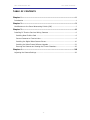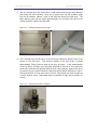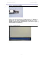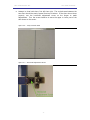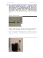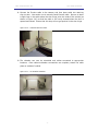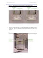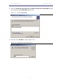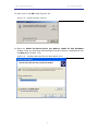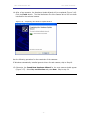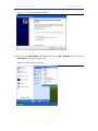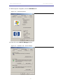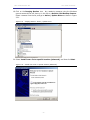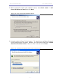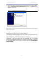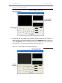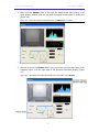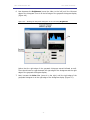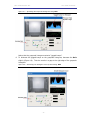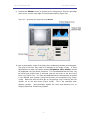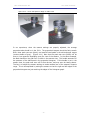
1
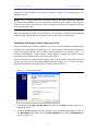
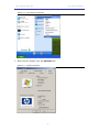
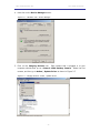
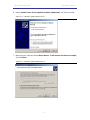
ADDENDUM TO MED-VFC VIDEO FEAR
CONDITIONING SYSTEMS
APPLIES TO MED-VFC-BW VIDEO FEAR CONDITIONING
BLACK & WHITE CAMERA UPGRADE
DOC-105
Rev. 2.1
Copyright © 2006
All Rights Reserved
Med Associates, Inc.
P.O. Box 319
St. Albans, Vermont 05478
www.med-associates.com
MED ASSOCIATES INC.
VFC B&W UPGRADE
- ii -
MED ASSOCIATES INC.
VFC B&W UPGRADE
TABLE OF CONTENTS
Chapter 1 ...............................................................................................1
Introduction ...................................................................................................... 1
Chapter 2 ...............................................................................................2
Modifications to the Sound Attenuating Cubicle (SAC) ............................................. 2
Chapter 3 ...............................................................................................8
Installing PC Firewire Card and Wiring Cameras ..................................................... 8
Installing New FireWire Card ............................................................................ 8
Connect Cameras to Firewire Hubs .................................................................... 8
Installing the Digital Video Camera Drivers ....................................................... 10
Installing the Video Freeze Software Upgrade ................................................... 22
Ensuring the Cameras are Viewing the Correct Chambers.................................... 26
Chapter 4 .............................................................................................28
Adjusting the Camera Settings ........................................................................... 28
- iii -
MED ASSOCIATES INC.
VFC B&W UPGRADE
- iv -
MED ASSOCIATES INC.
VFC B&W UPGRADE
CHAPTER 1
Introduction
This document describes changes to Video Freeze Software (SOF-843) that are specific to
the camera upgrade. The Video Freeze software functionality is identical to that
described in the Video Fear Conditioning User’s Manual with the exception of the
calibration features for the video cameras, which are described here.
This document also contains relevant information regarding the care and use of the black
and white video camera that is now included with the Video Fear Conditioning package.
Please note that this camera (part number VID-CAM-MONO-2) is a high quality research
instrument. This camera is mounted onto the inner surface of the left-side door on the
Sound Attenuating Cubicle (SAC). Never slam the SAC doors shut, as the jarring action
could damage the precision video camera.
Installation of the Video Freeze software requires a password that is issued by Med
Associates. Please complete the software registration card included with the system and
contact Med Associates for this password.
The following components are required to upgrade an existing Video Fear Conditioning
Package:
•
1 Left Door with Modified Hinges, Camera (with lens) and Camera Mount (Per
Chamber)
•
1 Right Door with Modified Hinges and Door Catch (Per Chamber)
•
1 Replacement Fire Wire Cable (Per Chamber)
•
5 Cable Clamps for Securing Cable to Cubicle (Per Chamber)
•
1 Firewire PCI Card (to be installed into PC) (Per System)
•
1 Firewire Hub (Per System)
- 1 -
MED ASSOCIATES INC.
VFC B&W UPGRADE
CHAPTER 2
Modifications to the Sound Attenuating Cubicle (SAC)
1. Disconnect and remove existing camera from Left Door. This should be set aside
and packaged for return shipment to MED Associates, Inc.
2. In order to remove the existing firewire cable and route the new cable properly,
the chamber will need to be removed from the cubicle. Disconnect accessories
from the VFC-716 connection panel prior to removal of chamber to prevent cable
or connector damage. It is advised to mark the location of the accessories when
disconnecting to ensure correct wiring when reinstalling. The main connections
to be removed are the shock operate cable, the grid harness cable, the cubicle
fan cable, the large 25-pin data cable and the 2-pin power cable.
3. Once the chamber has been removed, the existing Firewire cable can be removed
from the cubicle. Remove the upper portion of the cable plate on the side of the
cubicle to allow complete removal of the cable. This plate can remain off until
the new cable has been installed.
4. The existing doors of the cubicle may now be removed. Locate the hinge
retaining screw (one on each of the four hinges) and loosen. With the screws
loose, grasp the door by the top and bottom edge, pull away from the cubicle to
remove.
Figure 2.1 – Hinge Retaining Screw
- 2 -
MED ASSOCIATES INC.
VFC B&W UPGRADE
5. With the cubicle free from obstructions, install cable-retaining clips with adhesive
tape along left wall and back. Using the 3 screws from the left chamber guide
strip as an indicator, adhere 3 clips to left wall just above the guide strip. The
back retaining clips can be placed approximately ¾ inch above the floor of the
cubicle spaced 4 inches from each side.
Figure 2.2 – Installing Cable Retaining Clips
6. Prior to attaching the new doors, verify the hinge placement matches that of the
hinges on the old doors. The mounting flange of the new hinge is located
approximately 22mm from the edge of the door, as shown. If the measurement
of the old doors is 25mm, the cross piece attached to the side of the cubicle will
need to be removed and replaced with the new cross supplied. Attach new doors
to cubicle using the same method as removing the old doors described in step 4.
Slip keyed section of hinge over screw of cross. Once upper and lower hinges are
in place, tighten screw. Adjustment may be required to align doors properly for
closing.
Figure 2.3 – Verifying Placement of Hinges
- 3 -
MED ASSOCIATES INC.
VFC B&W UPGRADE
Figure 2.4 – Keyed Section of the Hinge
7. Close one door and verify even seal to weather stripping. If adjustment is
required, open door, loosen hinge-retaining screw and slide hinge in or out.
Retighten screw and verify seal. Adjust second door. It may take more than one
attempt to achieve an acceptable seal.
Figure 2.5 – Verify Even Door Seal
- 4 -
MED ASSOCIATES INC.
VFC B&W UPGRADE
a. Attempt to close both doors, first left then right. The vertical seam between the
two doors should be evenly spaced from top to bottom. If the doors do not close
properly, use the horizontal adjustment screw on the hinges to make
adjustments. Turn the screw clockwise to move the upper or lower part of the
door closer to the center.
Figure 2.6 – Verify Vertical Seam
Figure 2.7 – Horizontal Adjustment Screw
- 5 -
MED ASSOCIATES INC.
VFC B&W UPGRADE
8. With the doors properly adjusted, the grab portion of the catch can be installed
on the right door. Attach the catch to the post on the upper edge of the door.
Remove the protective film on the adhesive tape of the catch. Gently close the
door (right door only). While holding the door closed with one hand, press firmly
up on the catch to attach to ceiling. When you open the door the catch should
remain attached to ceiling. Close doors (left first) to verify catch will hold both
doors closed. You can add wood screws to secure the door catch to the ceiling if
desired.
Figure 2.8 – Installed Door Latch
9. Install the new Firewire cable. Route the cable through the retaining clips
extending the cable approximately 20 inches beyond the edge of the cubicle.
10. Attach the camera to the camera bracket mounted to the left door. Position the
camera at the bottom of the adjustment slot on the bracket and tighten
thumbscrews. The camera position can be fine-tuned during the calibration of
the camera.
Figure 2.9 – Installed Camera
- 6 -
MED ASSOCIATES INC.
VFC B&W UPGRADE
11. Connect the Firewire cable to the camera, and then place cable into retaining
clips on door. Use caution not to severely bend Firewire cable. Be sure to leave
a slight loop in the cable where the door hinge joins the inside of the cubicle (as
shown in Figure 2.10) so that the cable is not overly stressed when the door is
opened and closed. Ensure that this loop will not get pinched in the door hinge.
Figure 2.10 – Installed Firewire Cable
12. The chamber can now be reinstalled and cables connected to appropriate
locations. Once cable-to-chamber connections are complete, attach the cable
plate on outside of cubicle.
Figure 2.11 – Re-Installed Chamber
- 7 -
MED ASSOCIATES INC.
VFC B&W UPGRADE
CHAPTER 3
Installing PC Firewire Card and Wiring Cameras
Installing New FireWire Card
1.
Ensure that the power to the computer system is turned off. Discharge your
body’s static electric charge by touching a grounded surface — for example, the
metal surface of the power supply — before performing any hardware procedure.
Damage to system components, the Firewire card, and personal injury may result
if power is applied during installation.
2.
If you do not feel comfortable performing the installation, consult a qualified
computer technician.
Feel free to call Med Associates for assistance at
(802) 527-2343 in the US.
3.
Refer to the instructions included with the computer for the installation of a PCI
card.
4.
When installation is complete, power on the computer and allow the computer to
reboot. Windows should automatically install the drivers for the Firewire card.
5.
Once Windows has rebooted and installed the new Firewire card drivers, proceed
to connect the Firewire cameras to the computer as described in the next section.
Connect Cameras to Firewire Hubs
1. Locate the Firewire cable coming from each chamber. The Firewire cables are the
gray cable with red connector shown in Figure 3.1.
2. Connect the Firewire cables from Chambers 1 and 2 to one hub.
Firewire cables from Chambers 3 and 4 to the second hub.
Connect the
3. Figure 3.1 shows a typical hub configuration for a four-chamber Video Fear
Conditioning system. Note the use of two hubs. The silver hub on the left
connects to two chambers via the connections on the left. The other two
chambers are connected to the white hub on the right at the back of the hub.
The figure also shows the power supplies connected to each hub.
- 8 -
MED ASSOCIATES INC.
VFC B&W UPGRADE
Figure 3.1 – Wiring Scheme for Firewire Cameras in a Four-Chamber System
4.
Connect a Firewire cable from one of the Firewire cards in the computer to each
of the hubs. Figure 3.2 shows the Firewire cable connections at the rear of the
computer.
Figure 3.2 – Firewire Connections to the Computer
- 9 -
MED ASSOCIATES INC.
VFC B&W UPGRADE
Connect the power cables to the hubs (as shown in Figure 3.1) and plug them into
available outlets.
NOTE: Due to the high resolution of the video cameras and high frame rates supported
by Video Freeze Software (up to 30 frames per second on each camera), each Firewire
card can only support two cameras. Do not attempt to connect more than two cameras
to a single Firewire card.
After the cameras and hubs are connected to the computer, install the Med Associates
Firewire Digital Camera drivers according to the directions in the next section.
Installing the Digital Video Camera Drivers
After connecting the Firewire cameras and hubs to the computer, Windows may
automatically install generic camera drivers for each camera. Med Associates does not
support this generic driver, and the Video Freeze software will not function with it. If
Windows automatically installs generic camera drivers, update the camera drivers
according to the directions below, beginning with STEP 2.
Upon connecting the Firewire cameras and hubs to the computer, Windows may also
prompt the user with a Found New Hardware Wizard (Figure 3.3). If this is the case,
proceed according to the directions below, beginning with STEP 1.
Figure 3.3 – Found New Hardware
1. Choose the option No, not this time and click on the Next> button (Figure 3.3).
Proceed to step 6.
2. If the Found New Hardware screen (Figure 1) did not automatically appear, Click on
the Start Menu, and Right-click on the My Computer icon, and click Properties as
shown in Figure 3.4.
- 10 -
MED ASSOCIATES INC.
VFC B&W UPGRADE
Figure 3.4 – My Computer Properties
3. When Figure 3 appears, click the Hardware tab.
Figure 3.5 – System Properties
- 11 -
MED ASSOCIATES INC.
VFC B&W UPGRADE
4. Now click on the Device Manager button.
Figure 3.6 – Hardware Tab – Device Manager
5. Click on the Imaging Devices icon. Each camera that is plugged in to your
computer should show up as a Generic 1394 Desktop Camera. Select the first
camera, and then go to Action | Update Driver as shown in Figure 3.7.
Figure 3.7 – Imaging Devices –Action | Update Driver
- 12 -
MED ASSOCIATES INC.
VFC B&W UPGRADE
6. Select Install from a list or specific location (Advanced), and then click next.
Figure 3.8 – Hardware Update Wizard Part 1
7. When Figure 3.9 appears select Don’t search. I will choose the driver to install,
and click Next.
Figure 3.9 – Hardware Update Wizard Part 2
- 13 -
MED ASSOCIATES INC.
VFC B&W UPGRADE
8. When the Select the device driver you want to install for this hardware dialog
box comes up, select Have Disk (Figure 3.10).
Figure 3.10 – Selecting Have Disk
9. Now click on the Browse… button (Figure 3.11).
Figure 3.11 – Browsing for Video Camera Driver
- 14 -
MED ASSOCIATES INC.
VFC B&W UPGRADE
10. Browse to the MED Associates CD, and select the Driver\FireWire Camera
directory.
Figure 3.12 – Finding the Video Camera Driver
11. Select the MedCam.inf file and click Open.
Figure 3.13 – MedCam.inf File
- 15 -
MED ASSOCIATES INC.
VFC B&W UPGRADE
12. Next, click on the OK button (Figure 3.14).
Figure 3.14 – Install From Disk, Click OK
13. When the Select the device driver you want to install for this hardware
window comes up, make sure Med Associates Fire Wire Camera is selected and click
the Next button (Figure 3.15).
Figure 3.15 – Installing Med Associates Fire Wire Camera Driver
- 16 -
MED ASSOCIATES INC.
VFC B&W UPGRADE
14. After a few moments, the Hardware Update Wizard will be completed (Figure 3.16).
Click the Finish button. The Med Associates Fire Wire Camera driver has now been
installed for the selected camera.
Figure 3.16 – Completing the Hardware Update Wizard.
Use the following procedure for the remainder of the cameras:
If Windows automatically installed generic drivers for each camera, skip to Step 16.
15. Otherwise, the Found New Hardware Wizard for the next camera should appear
(Figure 3.17). Select No, not this time and press Next. Skip to step 20.
- 17 -
MED ASSOCIATES INC.
VFC B&W UPGRADE
Figure 3.17 – Found New Hardware Wizard
16. Click on the Start Menu, and Right-click on the My Computer icon, and click
Properties as shown in Figure 3.18.
Figure 3.18– My Computer Properties
- 18 -
MED ASSOCIATES INC.
VFC B&W UPGRADE
17. When Figure 3.19 appears, click the Hardware tab.
Figure 3.19 – System Properties
18. Now click on the Device Manager button.
Figure 3.20 – Hardware Tab – Device Manager
- 19 -
MED ASSOCIATES INC.
VFC B&W UPGRADE
19. Click on the Imaging Devices icon. Any remaining cameras using the Windows
generic camera driver will show up in this list as a Generic 1394 Desktop Camera.
Select a camera from the list, and go to Action | Update Driver as shown in Figure
3.21.
Figure 3.21 – Imaging Devices –Action | Update Driver
20. Select Install from a list or specific location (Advanced), and then click Next.
Figure 3.22 – Install from a list or specific location (Advanced).
- 20 -
MED ASSOCIATES INC.
VFC B&W UPGRADE
21. When prompted for search and installation options, select Don’t search.
choose the driver to install, and click Next.
I will
Figure 3.23- Driver Search and Installation Options
22. A window similar to Figure 3.24 will appear. The exact drivers available will depend
on the configuration of the system. However, one of the items in the list will be Med
Associates Fire Wire Camera. Select this item in the list and click Next.
Figure 3.24 – Selecting the Med Associates Firewire Camera Driver
- 21 -
MED ASSOCIATES INC.
VFC B&W UPGRADE
23. After a few moments, the Med Associates Firewire Camera Driver will be installed,
and the Completing Hardware Update Wizard will appear. Click Finish to close
the wizard (Figure 3.25).
Figure 3.25 – Completing the Hardware Update Wizard
Repeat steps 15 thru 23 until all cameras have been installed with the Med Associates
Firewire Camera Driver.
Installing the Video Freeze Software Upgrade
The Video Freeze Software Upgrade will need to be installed onto the existing Video Fear
Conditioning computer. Existing data files should not be impacted.
Insert the Video Freeze CD in the CD-ROM drive. The Install program should start
automatically. If the install program does not automatically start, open Windows
Explorer and navigate to the CD-ROM drive. Double click on Autorun.exe. A screen like
the one shown in Figure 3.26 will appear. Choose the last option To install Video
Freeze click here.
- 22 -
MED ASSOCIATES INC.
VFC B&W UPGRADE
Figure 3.26 – Welcome to Video Freeze
At the screen in Figure 3.27, click Next.
Figure 3.27 – Video Freeze Installer
The next screen shown in Figure 3.28, enter your Name, Organization and password. To
acquire the password, please contact Med Associates Sales at (802) 527-2343.
- 23 -
MED ASSOCIATES INC.
VFC B&W UPGRADE
Figure 3.28 – Customer Information
In the next screen choose the directory to place the installed files in.
Figure 3.29 – Installation Directory
- 24 -
MED ASSOCIATES INC.
VFC B&W UPGRADE
The following screen the user is prompted for the type of installation. Choose Typical
and click Next.
Figure 3.30– Setup Type
The screen in Figure 3.31 shows the summary of the options that have been selected.
Choose Back to change any of these, otherwise to continue with the installation, choose
Install.
Figure 3.31 – Installation Summary
- 25 -
MED ASSOCIATES INC.
VFC B&W UPGRADE
At this point the install will display a couple of status screens will appear. The user will
then be prompted with the last screen shown in Figure 3.32. Choose Finish.
Figure 3.32 – Installation Complete
Video Freeze software installation is now complete.
Ensuring the Cameras are Viewing the Correct Chambers
After the camera drivers are installed, they may not necessarily be in the desired order.
For example, the camera located in Chamber 1 may actually be configured for Chamber
3. To address this issue, complete the following:
1.
From Video Freeze Software, choose File | Camera Setup | Camera N, where
N is the camera number to check (Figure 3.33).
Figure 3.33 – Selecting a Camera for Viewing
- 26 -
MED ASSOCIATES INC.
VFC B&W UPGRADE
This will open the Calibrate Camera window (Figure 3.34). Refer to Section 4 Adjusting the Camera Settings for help in adjusting the video signal if no video
display is visible. The image in the display window is a live video feed from the selected
camera.
Figure 3.34– Calibrate Camera Window
2.
Determine which camera is running by waving a hand in front of each camera.
3.
Once it is determined which camera is running, put a label on that camera with
the corresponding camera number. Click Exit to close the Camera Calibrate
window.
4.
Repeat this process to determine the Camera numbers for each camera in the
system.
5.
If the cameras aren’t associated with the desired Chambers, they can be
exchanged from one chamber to another. Be sure to close the Video Freeze
Software, unplug each camera from its Firewire cable, and attach the Firewire
cable from the desired Chamber into the Firewire camera to be associated with
that Chamber.
6.
Restart Video Freeze software and check each camera by going to File |
Camera Setup | Camera N, where N is the camera number to check (Figure
3.33).
- 27 -
MED ASSOCIATES INC.
VFC B&W UPGRADE
CHAPTER 4
Adjusting the Camera Settings
Use the following procedure to ensure that the camera settings are properly adjusted for
best imaging results.
1. First ensure that the light sources are turned on for each fear conditioning
chamber (e.g. the fluorescent light above the conditioning chamber or the nearinfrared light box).
2. Next, go to the File menu in Video Freeze, select Camera Setup, and then the
camera number of the camera to be adjusted (Figure 4.1).
Figure 4.1 – File Menu
Med Associates uses the following convention when setting up Video Fear
Conditioning Systems prior to shipment: Camera 1 is configured to record video
from Chamber 1, Camera 2 is configured to record video from Chamber 2, Camera
3 is configured to record video from Chamber 3, and Camera 4 is configured to
record video from Chamber 4.
The video image initially displayed in the Calibrate window may be of poor
quality, either much too dark or much too light.
The following example will
demonstrate how to configure the camera settings in the extreme case when all
of the camera controls (Brightness, Gain, and Shutter) are all at their minimal
settings (green slider bars all the way to the left). (Figure 4.2)
- 28 -
MED ASSOCIATES INC.
VFC B&W UPGRADE
Figure 4.2 – Black Video Image
3. Notice that the video image in the Calibrate window is totally black (Figure 4.2).
Begin adjusting the camera settings by moving the Brightness slider to the right.
As the Brightness slider is moved back and forth, a single narrow peak will move
back and forth in the grayscale histogram display (Figure 4.3).
Figure 4.3 – Narrow Peak in the Grayscale Histogram
- 29 -
MED ASSOCIATES INC.
VFC B&W UPGRADE
4. Next, move the Shutter slider to the right. An image should start forming in the
video display window, and the grayscale histogram should start to spread out
(Figure 4.4).
Figure 4.4 –Grayscale Histogram Spreading Out as Shutter is Increased
5. Continue to move the Shutter slider to the right until the right-most edge of the
histogram curve is at the right edge of the grayscale histogram display (Figure
4.5).
Figure 4.5 – Spreading the Grayscale Histogram to the Right Using Shutter
- 30 -
MED ASSOCIATES INC.
VFC B&W UPGRADE
6. Now decrease the Brightness (move the slider to the left) until the left-most
edge of the histogram curve is at the left edge of the grayscale histogram display
(Figure 4.6).
Figure 4.6 – Shifting the Grayscale Histogram to the Left Using Brightness
Notice that the right edge of the grayscale histogram moved leftward as well.
There should now be a gap between the right edge of the histogram and the right
edge of the grayscale histogram display.
7. Next, increase the Gain slider (move it to the right) until the right edge of the
grayscale histogram is at the right edge of the histogram display (Figure 4.7).
- 31 -
MED ASSOCIATES INC.
VFC B&W UPGRADE
Figure 4.7 – Spreading the Grayscale Histogram Using Gain
Notice that the grayscale histogram contains “jagged bumps”.
8. To eliminate the jagged bumps on the grayscale histogram, decrease the Gain
slightly (Figure 4.8). This also results in a gap at the right edge of the grayscale
histogram.
Figure 4.8 – Smoothing the Histogram Curve by Decreasing Gain
- 32 -
MED ASSOCIATES INC.
VFC B&W UPGRADE
9. Increase the Shutter control to spread out the histogram so that the right edge
of the curve is at the right edge of the histogram display (Figure 4.9).
Figure 4.9 – Spreading the Histogram Using Shutter
10. Now a good quality image of the empty fear conditioning chamber should appear.
The focus of the lens may need to be adjusted if the image is fuzzy. If focus
adjustments are made, the camera settings (Brightness, Gain, Shutter) should
be readjusted using the above procedure. It is recommended that the focus ring
be locked once proper focus is achieved (use the set screw on the lens barrel
focus ring; Figure 4.10). It is also recommended that the lens aperture be locked
in the maximal open position (using the set screw on the aperture ring; Figure
4.10B). Make sure that the white dot on the aperture ring is lined up with the
number 1.4 on the lens barrel (Figure 4.10B). This is the maximally open
aperture position. Med Associates adjusts the focus and aperture prior to
shipping Video Fear Conditioning systems.
- 33 -
MED ASSOCIATES INC.
VFC B&W UPGRADE
Figure 4.10 – Focus and Aperture Rings on Video Lens
In our experience, when the camera settings are properly adjusted, the average
grayscale value should be in the 130’s. The grayscale histogram should be fairly smooth
with a clear peak near zero (black), and several broad peaks in the mid and upper ranges
(various shades of gray). (Figure 4.11) Note that the peak near zero (black) will be
more or less apparent depending upon the view of the camera. In the above example,
the black handle on the grid floor is visible in the camera view. This handle accounts for
the presence of the black peak in the grayscale histogram. If this handle is not in the
camera view, the peak near zero will be less obvious, and may even be totally absent.
The key is to adjust the camera settings to make maximal use of the camera’s dynamic
range. This is accomplished by setting the camera so that the right and left edges of the
grayscale histogram are just reaching the edges of the histogram graph.
- 34 -
MED ASSOCIATES INC.
VFC B&W UPGRADE
Figure 4.11 – Grayscale Histogram Characteristics of Properly Calibrated Camera
Once the calibration settings are satisfactory, click the Save button to save the
Brightness, Gain, and Shutter settings. Then click Exit to return to Video Freeze
software. At this point, experiments can be setup as described in the main user’s
manual.
Feel free to contactl Med Associates technical support should there be difficulties in
properly calibrating the cameras. In the United States, dial (802) 527-2343 to reach our
technical support.
- 35 -