1
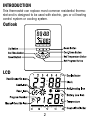
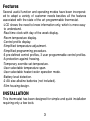
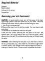
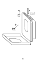
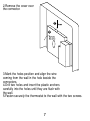
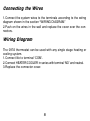
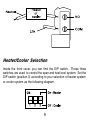
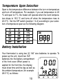
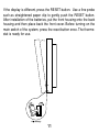
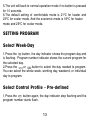
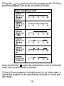
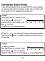
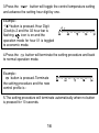
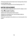
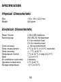
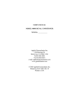
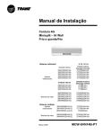
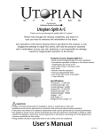
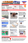
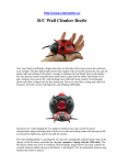
Cat No. : 097A
Advanced Programmable Thermostat
User Manual
Ta b l e o f C o n t e n t
TABLE OF CONTENT..………………….................1
INTRODUCTION……………………..…...........2-3
INSTALLATION ……………..………...............3-11
SETTING CLOCK …………………………......…..12
SETTING CONTROL TEMPERATURE …..…12-13
SETTING PROGRAM ……………...............13-16
TEMPORARY OVERRIDE ……………................17
ANTI-FREEZING MODE ……………………... 17
BATTERY REPLACEMENT……………….....…...18
SPECIFICATION …………………………...……...19
1
INTRODUCTION
This thermostat can replace most common residential thermostat and is designed to be used with electric, gas or oil heating
control system or cooling system.
Outlook
LCD
2
Features
Several useful function and operating modes have been incorporated to adapt a variety of customer needs besides all the features
associated with the state of the art programmable thermostat.
-LCD shows the need to know information only, which is more easy
to understand.
-Real time clock with day of the week display.
-Room temperature display.
-Control profile display.
-Simplified temperature adjustment.
-Simplified programming procedure.
-6 pre-defined control profiles, 3 user programmable control profiles.
-A protection against freezing.
-Temporary override set-temperature.
-User selectable temperature span.
-User selectable heater/cooler operation mode.
-Battery level detection.
-2 AA size alkaline batteries (not included).
-Slim housing design.
INSTALLATION
This thermostat has been designed for simple and quick installation
requiring only a few tools
3
Required Material
Hammer
Masking tape
Drill and 3/16” drill bit
Screwdriver
Removing your old thermostat
CAUTION : to avoid electric shock, turn off the power of the heating/cooling system at the main power box in your home. Read the
following instructions carefully before disconnecting the wires.
1.Turn off your old thermostat.
2.Remove the cover from the old thermostat. You may have to pull
extra hard.
3.Unscrew the old thermostat from the wall plate.
4.Now find the screws attaching the wall plate to the wall, and
remove them. You should now be able to pull the wall plate a small
distance from the wall. Do not disconnect any wire yet, simply locate
the wires.
WARNING: After removing the wall plate, if you find that it is mounted on a junction box (e.g. a box similar to one behind a light switch
or electric outlet), high voltage circuit may be present and there is
a danger of electric shock. Please consult a qualified electrician.
4
Wire Labeling
1.Disconnect and identify each wire.
2.You may wish to tape the wires to the wall to keep them from slipping through the hole in the wall. If the hole in the wall is larger than
necessary, fill it in order to prevent hot or cold air to penetrate the
thermostat. In this manner, the thermostat will behave perfectly.
Choosing a Location
Note: for a new installation, choose a mounting location about five
feet (1.5 meter) above the floor in an area with good air circulation
and away from.
1.Drafts of dead air sports.
2.Air ducts.
3.Radiant heat from the sun or appliances.
4.Concealed pipes and chimneys.
Mounting
Mounting the thermostat onto the wall
1.Remove completely the front housing of the thermostat.
5
6
2.Remove the cover over
the connector.
3.Mark the holes position and align the wire
coming from the wall in the hole beside the
connectors.
4.Drill two holes and insert the plastic anchors
carefully into the holes until they are flush with
the wall.
5.Fasten securely the thermostat to the wall with the two screws.
7
Connecting the Wires
1.Connect the system wires to the terminals according to the wiring
diagram shown in the section “WIRING DIAGRAM”
2.Push on the wires in the wall and replace the cover over the connectors.
Wiring Diagram
The 097A thermostat can be used with any single stage heating or
cooling system.
1.Connect life to terminal ‘COM’.
2.Connect HEATER/COOLER in series with terminal ‘NO’ and neutral.
3.Replace the connector cover.
8
Heater/Cooler Selection
Inside the front cover, you can find the DIP switch, These three
switches are used to control the span and heat/cool system. Set the
DIP switch (position 3) according to your selection of heater system
or cooler system as the following diagram.
9
Temperature Span Selection
Span is the temperature difference between the turn on temperature
and turn off temperature. For example, if you set temperature to 20
ºC and span to 1ºC, the heater will operate when the room temperature drops to 19.5 ºC and turns off when the temperature rises to
20.5 ºC. Set the DIP switch (position 1 & 2) according to your selection of temperature span as the following diagram.
Battery Installation
Your thermostat is using two (2) “AA” size batteries to operate. To
power-up the unit, insert two “AA”
batteries into the battery compartment
of the front cover. When power is
applied for the first time, the display
must show time and the day as well as
the ambient temperature (for example
28.5 ºC) as follows:
10
If the display is different, press the RESET button. Use a fine probe
such as straightened paper clip to gently push the RESET button.
After installation of the batteries, put the front housing onto the back
housing and then place back the front cover. Before turning on the
main switch of the system, press the reset button once. The thermostat is ready for use.
11
SETTING CLOCK
1.Press the
button to clear all digits except the day indicator and
the time display. The Day indicator is flashing.
2.While Day indicator is flashing, press
or
button to adjust.
3.Press the
button again, hour digits are flashing instead of day
indicator. Press
or
button to adjust. Press and hold the
or
button will speed up the adjustment rate.
4.Press the button again, minute digits are flashing instead of hour
digit. Press
or
button to adjust. Press and hold the
or
button will speed up the adjustment rate.
5.Press the
button again to return to normal operation mode.
6.The unit will return to normal operation mode if no key is pressed
for 10 seconds.
SETTING CONTROL TEMPERATURE
1.Press the
button to display the pre-defined set temperature.
2.Press the
button to toggle between the setting of economic
mode and comfortable mode.
3.Press the
or
button to increase/decrease the set temperature by 0.5 ºC.
4.Press the
button again to save the set temperature.
12
5.The unit will back to normal operation mode if no button is pressed
for 10 seconds.
6.The default setting of comfortable mode is 21ºC for heater and
23ºC for cooler mode. And the economic mode is 18ºC for heater
mode and 26ºC for cooler mode.
SETTING PROGRAM
Select Week-Day
1.Press the
button, the day indicator shows the program day and
is flashing. Program number indicator shows the current program for
the selected day.
2.Press the
or
button to select the day needed to program.
You can select the whole week, working day, weekend, or individual
day to program.
Select Control Profile - Pre-defined
1.Press the
button again, the day indicator stop flashing and the
program number starts flash.
13
2.Press the
or
button to select the program profile. P1-P6 are
predefined program, their profile are shown as follows.
where the black dot
means the selected hour is set to comforable
mode, else economic mode is selected.
3.If any of these programs is selected, press the
button again to
confirm this program for the specified day and back to normal operation mode.
14
User-defined Control Profile
If user-defined program number is selected (P7-P9), press the button will stop flashing of the program number and start flashing the
control profile bar with displaying the selected hour.
Example:
Hour Dight(Clock) is 0 and the 00 hour
bar is flashing.
icon is on if
previous setting is comfortable mode,
else
icon is on.
e.g. Hour 00-23 are comfortable mode.
2.Press the
or
hour by one, the or
vious setting.
button will increase or decrease the setting
icon will be turned on according to the pre-
Example:
button is pressed.
Hour Digit (Clock) is 1 and the 01hour
bar is flashing.
icon is on and the
operation mode for hour 00 is unchanged, i.e., at comfortable mode.
15
3.Press the
button will toggle the control temperature setting
and advance the setting hour digit by one.
Example:
button is pressed. Hour Digit
(Clock)is 2 and the 02 hour bar is
flashing.
icon is on and the
operation mode for hour 01 is toggled
to economic mode.
4.Press the
button will terminate the setting procedure and back
to normal operation mode.
Example:
button is pressed. Terminate
the setting procedure and the new
control profile is :
5.The setting procedure will terminate automatically when no button
is pressed for 10 seconds.
16
TEMPORARY OVERRIDE
Override the Operation Mode
At the normal operation mode, press the
button will toggle the
current set temperature to comfortable mode or economic mode. If
the operation mode is being override, the icon will be turned on
with the current operation mode icon.
Override the Setting Temperature
1.At the normal operation mode, the current set temperature can be
override by pressing the
or
button. When override, the new
set temperature will be displayed with turning on the icon and off
both the
and icon.
2.Press other button (except the
or
button) will terminate the
setting procedure and back to normal mode with the new setting.
3.The unit will back to normal operation mode automatically when no
button is pressed for 10 seconds.
ANIT-FREEZING MODE
1.Pressing the
and
buttons simultaneously will activate the
anti-freezing mode (for heater mode only).The
icon and the
icon will be turned on while both the and icon will be turned off.
17
2.Pressing any button will terminate the anti-freezing mode and back
to normal operation mode.
3.The default set temperature of the anti-freezing mode is 7ºC.
BATTERY REPLACEMENT
It is recommended to replace the batteries when the display is showing the
. To replace the battery,
1.Turn off your heater or cooler first.
2.Remove the front housing of the thermostat.
3.Replace the old batteries with 2 new AA alkaline batteries.
4.Replace the front housing.
5.Press the reset button once and then turn on the main switch of the
system.
18
SPECIFICATION
Physical Characteristic
Size
Weight
116 x 100 x 23.5 mm
220 gram
Electrical Characteristic
Power Source
Switching cap
Clock accuracy
Temp. measurement
Temp accuracy
Temperature Control
Span
Air conditioner cycle time
Operation temperature
Storage temperature
2 AA (LR6) batteries
250 VAC 50 Hz Maximum
5 A for resistive load
3 A for inductive load
+/- 60 seconds/month
0 ºC to 40 ºC in 0.5 ºC resolution
+/- 1 ºC at 20 ºC
7 ºC to 30 ºC in step of 0.5 ºC
1,2,3 or 4 ºC
3 minutes
0 ºC to 40 ºC
-10 ºC to 60 ºC
19