1
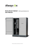
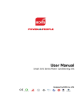
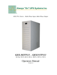
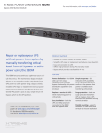
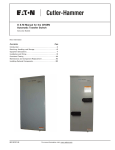
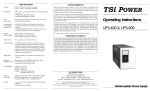
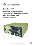
BP12011/BP12020/BP12030
UPS Bypass System
T.V.S.S. Filter
Optional Automatic Transfer Switch
Optional Dry Contact Status
User’s Manual
TABLE OF CONTENTS
INTRODUCTION……………………………………………………………………………….. 1
1. IMPORTANT SAFETY INSTRUCTIONS……………………………………………..……….. 1
2. INSTALLATION ………………...……………………………..…..………………………. 2
3. PRESENTATION………………………………………………...…………………………… 3
4. BLOCK DIAGRAMS………………………………………………………………………… 7
5. OPERATION……………………………………………………...………………………… 10
APPENDIX A. TROUBLESHOOTING……………………………………...…………………… 11
APPENDIX B. SPECIFICATIONS……..………………………………………..………………. 11
CONTACT INFORMATION……………………………………………………………………… 12
Please read and save this manual!
Thank you for selecting the Always “On” UPS Bypass Line Conditioner. It provides you with a high degree of
protection for connected critical loads. This manual is a guide for Bypass System installation and use. It
includes important safety instructions for correct operation and installation. Please read this manual in its
entirety before setting up, installing and powering up the equipment. If you should encounter any problem,
please refer to this manual before calling customer service.
This unit is designed as a Wrap-Around Bypass with manual or (optional) automatic transfer from UPS power to
utility to allow for maintenance or repair of the UPS system without interruption of power to the load. When the
system is in Bypass Mode, the unit incorporates an Always “On” TVSS Filter, which regulates and filters the utility
power to the critical loads, ensuring cleaned power at all times.
OPTIONAL AUTOMATIC TRANSFER SWITCH WITH DRY CONTACT STATUS:
The intelligence built into the Bypass unit recognizes when the UPS is supplying power and, in the event that the
UPS output power is lost and utility is still present, it will automatically switch to Bypass Mode and the
communications will notify the connected equipment that they are no longer running off UPS power. This will
allow the user to program a switch in equipment operation, or remote status, so in the unlikely event of a power
outage while the system is in Bypass Mode, the connected loads can be prepared.
1. IMPORTANT SAFETY INSTRUCTIONS
●
●
●
●
WARNING (SAVE THESE INSTRUCTIONS): This manual contains important instructions that should
be followed during installation and maintenance.
WARNING (Controlled Environment): Intended for installation in a controlled environment.
CAUTION: Risk of electric shock; do not remove cover. No user serviceable parts inside. Refer
servicing to qualified service personnel.
CAUTION: Avoid exposure to direct sunlight, stoves or any other heat source.
M1002_BP-12011,12020,12030_Bypass Manual V1.4 2012-06-12.doc
1
●
●
CAUTION: To prevent overheating, make sure the ventilation openings of the unit are not covered.
CAUTION: Keep moisture and dust away.
2. INSTALLATION
2.1 Inspection:
Inspect unit upon receipt. The packaging is recyclable.
2.2 Placement:
Install in a controlled area with adequate airflow and free of excessive dust. Do not operate in
an outdoor area.
2.3 Utility Power: Be sure the polarities and voltage match the rating of the unit. In addition, check that the
loads being protected are within the capacity of the unit. If the capacity is not sufficient, the
input circuit breaker will trip or fuse will open.
2.4 Connections and Startup:
1.
2.
3.
4.
5.
6.
7.
Connect UPS Input and Output cables between Bypass module and AC Input and AC output
receptacles located on rear panel of UPS (Do not turn UPS ON).
If UPS features Form “C” Dry Contact Communications, connect remote monitoring device to Dry
Contact terminal block as required.
If UPS features an Automatic Transfer Switch, place Bypass Mode Select Switch to “Auto” position.
If UPS features Manual Transfer Switch, place Bypass Mode Select Switch to “Bypass” position.
Plug Bypass Input AC power cord into utility AC supply.
“Bypass” and “Output” indicators will illuminate, indicating system Bypass Mode.
AC power will be present at UPS input. UPS will enter Standby Mode.
Turn UPS ON.
UPS will perform a start up sequence.
If UPS features an Automatic Transfer Switch, once power is available at the UPS output,
the Bypass module Automatic Transfer Switch will switch to Normal Mode. “Bypass”
indicator will go out; “Output” indicator will remain ON.
If UPS features a Manual Transfer Switch, once UPS has performed start up sequence,
place switch to UPS/DISABLE mode and module will provide UPS power.
Connect loads sequentially to output receptacles of the Bypass System.
Place Mode Select Switch in position as required.
M1002_BP-12011,12020,12030_Bypass Manual V1.4 2012-06-12.doc
2
3. PRESENTATION
Figure 3.1:
BP-12011-ATS-DCC
Dry Contact Wiring Colours
(Alternate Colours in Parentheses)
Normally Open
Yellow (Green/Yellow)
Normally Closed
White (Blue)
Common (Ground) Black (Brown)
Output Power Indicator
– illuminated whenever
output power is available.
Bypass Indicator
- illuminated when the
transfer switch is supplying
Bypass power to the loads
DRY CONTACT
NC C NO
Blk – C
Wht – NC
Grn – NO
BUCK
BYPASS
OUTPUT
BOOST
Bypass AC
Protection
Fuse
AUTO
DISABLE / UPS
BYPASS
FUSE
3 Position
Bypass Mode
Select Switch
Bypass Power Voltage Regulation (AVR) Indicators:
“Buck” illuminated – reducing high input voltage
“Boost” illuminated – increasing low input voltage
UPS POWER
CORDS
UPS Input &
Output
Power Cords
Outlets for
Load Power
Distribution
INPUT AC
Utility Input
Power Cord
connection
M1002_BP-12011,12020,12030_Bypass Manual V1.4 2012-06-12.doc
3
Figure 3.2:
BP-12011 with Manual Transfer Switch
Output Power Indicator
– illuminated whenever
output power is available.
Bypass Indicator
- illuminated when the
transfer switch is supplying
Bypass power to the loads
BUCK
BYPASS
OUTPUT
Bypass AC
Protection
Fuse
BOOST
BYPASS
DISABLE / UPS
FUSE
Bypass Power Voltage Regulation (AVR) Indicators:
“Buck” illuminated – reducing high input voltage
“Boost” illuminated – increasing low input voltage
UPS POWER
CORDS
UPS Input &
Output
Power Cords
2 Position
Bypass Mode
Select Switch
Outlets for
Load Power
Distribution
INPUT AC
Utility Input
Power Cord
connection
M1002_BP-12011,12020,12030_Bypass Manual V1.4 2012-06-12.doc
4
Figure 3.3:
BP-12020-ATS-DCC / BP12030-ATS-DCC
Bypass Indicator
- illuminated when the
transfer switch is supplying
Bypass power to the loads
Output Power Indicator
– illuminated whenever
output power is available.
Dry Contact Wiring Colours
(Alternate Colours in Parentheses)
Normally Open
Yellow (Green/Yellow)
Normally Closed
White (Blue)
Common (Ground) Black (Brown)
DRY CONTACT
NO C NC
Dry Contact
Status
Output
Connections
BYPASS OUTPUT
AUTO
DISABLE / UPS
BYPASS
3 Position
Bypass Mode
Select Switch
Utility Input
Power Cord
connection
UPS
INPUT
Outlets for
Load Power
Distribution
UPS
OUTPUT
UPS Input &
Output
Power Cords
M1002_BP-12011,12020,12030_Bypass Manual V1.4 2012-06-12.doc
5
Figure 3.4:
BP-12020 / BP-12030 with Manual Transfer Switch
8. Bypass Indicator
- illuminated when the
transfer switch is supplying
Bypass power to the loads
Output Power Indicator
– illuminated whenever
output power is available.
BYPASS OUTPUT
BYPASS
DISABLE / UPS
2 Position
Bypass Mode
Select Switch
Utility Input
Power Cord
connection
UPS
INPUT
Outlets for
Load Power
Distribution
UPS
OUTPUT
UPS Input &
Output
Power Cords
M1002_BP-12011,12020,12030_Bypass Manual V1.4 2012-06-12.doc
6
4. BLOCK DIAGRAMS
4.1 Block Diagram for BP12011-ATS-DCC:
DRY CONTACT
NC NO
BUCK
YEL
UTILITY
AC
5-15P
FUSE
BOOST
YEL
AutoVoltage
Regulator
TVSS
Filter
COM
OUTPUT
POWER
BYPASS
GRN
NORMAL
MODE
SWITCH
AUTO
UPS / DISABLE
BYPASS
BYPASS
AC
RED
AC
OUT
IN
POWER TO LOADS
BYPASS
MODE
Dry Contact Wiring Colours
(Alternate Colours in Parentheses)
Normally Open
Yellow (Green/Yellow)
Normally Closed
White (Blue)
Common (Ground) Black (Brown)
UPS
ELECTRONICS
1500VA Max.
4.2 Block Diagram for BP12011 (with Manual Transfer Switch):
BUCK
YEL
UTILITY
AC
5-15P
FUSE
TVSS
Filter
BOOST
YEL
AutoVoltage
Regulator
OUTPUT
POWER
GRN
BYPASS
NORMAL
MODE
SWITCH
BYPASS
AC
RED
BYPASS
UPS /
DISABLE
BYPASS
MODE
POWER TO LOADS
AC
OUT
IN
UPS
ELECTRONICS
1500VA Max.
M1002_BP-12011,12020,12030_Bypass Manual V1.4 2012-06-12.doc
7
4.3 Block Diagram for BP12020-ATS-DCC:
DRY
N NO
UTILITY
AC
OUTPUT
POWER
T.V.S.S.
5-15R
COM
BYPASS
GRN
FILTER
NORMAL
MODE
SWITCH
AUTO
UPS / DISABLE
BYPASS
BYPASS
5-15R
RED
POWER TO LOADS
BYPASS
MODE
5-15P
5-15R
5-15P
AC
AC
IN
OUT
UPS
ELECTRONICS
Dry Contact Wiring Colours
(Alternate Colours in Parentheses)
Normally Open
Yellow (Green/Yellow)
Normally Closed
White (Blue)
Common (Ground) Black (Brown)
4.4 Block Diagram for BP12020 (with Manual Transfer Switch):
UTILITY
AC
OUTPUT
POWER
T.V.S.S.
5-15R
BYPASS
GRN
FILTER
NORMAL
MODE
SWITCH
BYPASS
POWER TO LOADS
UPS / DISABLE
BYPASS
5-15R
5-15P
RED
BYPASS
MODE
5-15P
5-15R
AC
IN
A
OUT
UPS
ELECTRONICS
M1002_BP-12011,12020,12030_Bypass Manual V1.4 2012-06-12.doc
8
4.5 Block Diagram for BP12030-ATS-DCC:
DRY CONTACT
NC NO
UTILITY
AC
OUTPUT
POWER
T.V.S.S.
L5-30P
COM
BYPASS
GRN
FILTER
NORMAL
MODE
SWITCH
AUTO
UPS / DISABLE
BYPASS
BYPASS
L5-30R
L5-30P
RED
POWER TO LOADS
BYPASS
MODE
L5-30P
L5-30R
AC
IN
AC
OUT
UPS
ELECTRONICS
Dry Contact Wiring Colours
(Alternate Colours in Parentheses)
Normally Open
Yellow (Green/Yellow)
Normally Closed
White (Blue)
Common (Ground) Black (Brown)
4.6 Block Diagram for BP12030 (with Manual Transfer Switch):
UTILITY
AC
OUTPUT
POWER
T.V.S.S.
L5-30P
BYPASS
GRN
FILTER
NORMAL
MODE
SWITCH
BYPASS
POWER TO LOADS
UPS / DISABLE
BYPASS
L5-30R
L5-30P
RED
BYPASS
MODE
L5-30P
L5-30R
AC
IN
AC
OUT
UPS
ELECTRONICS
M1002_BP-12011,12020,12030_Bypass Manual V1.4 2012-06-12.doc
9
5. OPERATION
For models featuring an Automatic Transfer Switch:
5.1 Mode Switch in “AUTO” Position:
This position provides an automatic transfer switch (ATS) between the UPS supplied power and the
Bypass (or alternate) power. Priority for output power selection is given to the UPS source.
If the UPS power is removed (UPS turned OFF, UPS output unplugged, etc.), the ATS will switch to
Bypass Mode automatically and maintain power to the load. The Bypass LED will illuminate. When UPS
power is re-established, the ATS will automatically switch back to normal mode and supply UPS power to
the loads. The Bypass LED will go out.
5.2 Mode Switch in “UPS” Position:
With the switch in this position, the automatic transfer is disabled and the switch is locked to only supply
UPS power to the load. The UPS output is fed to the Bypass System load receptacles. The loads will
lose power if the UPS power is removed.
5.3 Mode Switch in “BYPASS” Position
This causes a manual transfer to Bypass mode. UPS power is removed from the load and Bypass
power is conditioned by the Always “On” TVSS filter, resulting in cleaned power that is applied to the
load. The Bypass LED will be illuminated when in this mode.
This position relies on Bypass power to be available, and the switching action to Bypass mode is
inhibited if Bypass power is not present at the transfer switch. If the Bypass LED is not illuminated when
the Mode Switch is in this position, the transfer to Bypass has not occurred.
For models featuring a Manual Transfer Switch:
5.4 Mode Switch in “BYPASS” Position:
With the switch in the “BYPASS” position, unit is providing AC power directly from AC supply.
5.5 Mode Switch in “UPS/DISABLE” Position:
With the switch in the “UPS/DISABLE” position, unit is providing power from the output of the UPS.
5.6 Indicators:
Output LED – illuminated whenever output power is available to the load receptacles, in either UPS
powered or Bypass modes.
Bypass LED – illuminated when the transfer switch is in the Bypass position and Bypass power is
feeding the load receptacles.
For BP12011 11A models:
Buck LED – turns on when automatic voltage regulator (AVR) is reducing high input utility voltage for the
Bypass switch.
Boost LED – turns on when automatic voltage regulator (AVR) is increasing low input utility voltage for
the Bypass switch.
M1002_BP-12011,12020,12030_Bypass Manual V1.4 2012-06-12.doc
10
APPENDIX A. TROUBLESHOOTING
PROBLEM
Cannot be
switched to
Bypass Mode
POSSIBLE CAUSE
ACTION TO TAKE
Utility not available at input of bypass Confirm utility supply and connection
system
Bypass AC fuse has opened
Replace fuse
APPENDIX B. SPECIFICATIONS
INPUT
OUTPUT
PROTECTION
OPTIONS
Voltage
Frequency
Voltage
Capacity
Frequency
Number of outlets
Overload (Bypass Mode) [11A only]
Short Circuit (Bypass Mode) [11A only]
Transient Suppression
Automatic Transfer Switch
Dry Contact Interface
11A Model: 120VAC +/- 30% (80-150VAC)
20A or 30A Model: 120VAC nominal
50 or 60 Hz
11A Model: 120VAC +/- 10% (108-132VAC)
20A or 30A Model: 120VAC nominal
11A, 20A or 30A
50 or 60 Hz
4 [5-15R] (11A) or 6 [5-15R] (20A or 30A)
Fuse
Fuse
150V Clamping Voltage
5700 Joules
20,000 Amps
< 1 nano second response
Optional
Optional Form “C” with ATS models
©2005. September 15
All Rights Reserved.
All trademarks are the exclusive property of their respective owners. Specifications are subject to change without
prior notice due to upgrades in technology.
M1002_BP-12011,12020,12030_Bypass Manual V1.4 2012-06-12.doc
11
CONTACT INFORMATION
Additional Purchases or Upgrades
Always “On” UPS Systems Inc.
Bldg 1 – 150 Campion Road,
Kelowna, BC, Canada, V1X 7S8
Phone: (250) 491-9777 Ext 451
Fax:
(250) 491-9775
Email: [email protected]
Website: www.alwaysonups.com
QA / Warranty Questions
Always “On” UPS Systems Inc.
Bldg 1 – 150 Campion Road,
Kelowna, BC, Canada, V1X 7S8
Phone: (250) 491-9777 Ext 209
Fax:
(250) 491-9775
Email: [email protected]
Website: www.alwaysonups.com
Software Questions
Always “On” UPS Systems Inc.
Bldg 1 – 150 Campion Road,
Kelowna, BC, Canada, V1X 7S8
Phone: (250) 491-9777 Ext 204
Fax:
(250) 491-9775
Email: [email protected]
Website: www.alwaysonups.com
M1002_BP-12011,12020,12030_Bypass Manual V1.4 2012-06-12.doc
12