1
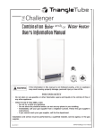
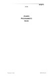
XZ020
ACQIRIS CC10X FAMILY OF COMPACTPCI CRATES
USER MANUAL
Models covered :
CC103 / CC105 / CC108
CC10X Family of CompactPCI Crates User Manual
ZM020020A RevD
August 2004
The information in this document is subject to change without notice and may not be construed as in any
way as a commitment by Acqiris. While Acqiris makes every effort to ensure the accuracy and contents
of the document it assumes no responsibility for any errors that may appear.
All software described in the document is furnished under license. The software may only be used and
copied in accordance with the terms of license. Instrumentation firmware is thoroughly tested and thought
to be functional but it is supplied “as is” with no warranty for specified performance. No responsibility is
assumed for the use or the reliability of software, firmware or any equipment that is not supplied by
Acqiris SA or its affiliated companies.
Any versions of this manual which are supplied with a purchased product will be replaced at your request
with the latest revision in electronic format. At Acqiris we appreciate and encourage customer input. If
you have a suggestion related to the content of this manual or the presentation of information, please
contact your local Acqiris representative or Acqiris Technical Support ([email protected]) or come
visit our web site at http://www.acqiris.com.
Trademarks: product and company names listed are trademarks or trade names of their respective
companies.
Acqiris Headquarters :
Acqiris USA :
Acqiris Asia-Pacific :
Acqiris SA
18, chemin des Aulx
CH-1228 Plan-les-Ouates
Geneva
Switzerland
Acqiris LLC
234 Cromwell Hill Road
P.O. Box 2203
Monroe, NY 10950-1430
USA
Acqiris Pty Ltd
Suite 7, Level 1
407 Canterbury Road
P.O. Box 13
Surrey Hills 3127
Australia
Tel: +41 22 884 33 90
Tel: 845 782 6544
Tel: +61 3 9888 4586
Fax: +41 22 884 33 99
Fax: 845 782 4745
Fax: +61 2 9849 0861
© Copyright August 2004, Acqiris SA. All rights reserved.
CC10X Family of CompactPCI Crates User Manual
Page 2 of 27
CONTENTS
1.
OUT OF THE BOX ................................................................................................ 4
1.1.
1.2.
1.3.
1.4.
1.5.
1.6.
1.7.
1.8.
Message to the User...................................................................................................................... 4
Before Using Your Crate .............................................................................................................. 4
Organization of This Manual ........................................................................................................ 4
Conventions Used in This Manual................................................................................................ 4
Disclaimer and Safety................................................................................................................... 5
Warning Regarding Medical Use.................................................................................................. 5
Packaging and Handling ............................................................................................................... 6
Optional Equipment...................................................................................................................... 6
1.8.1.
Rack-mount Adapter.............................................................................................................. 6
1.8.2.
Handles for Rack Mounted .................................................................................................... 7
1.8.3.
Carrying Handle and Feet ...................................................................................................... 7
1.8.4.
CompactPCI 6U to 3U Slot Adapter...................................................................................... 7
1.8.5.
Filler Plug-in.......................................................................................................................... 7
1.9.
Warranty ....................................................................................................................................... 8
1.10.
Warranty and Repair Return Procedure ........................................................................................ 8
1.11.
Maintenance.................................................................................................................................. 8
1.12.
Cleaning........................................................................................................................................ 8
2.
INSTALLATION.................................................................................................... 9
2.1.
2.2.
2.3.
2.4.
Configuration................................................................................................................................ 9
Site Considerations ..................................................................................................................... 10
Rack Mounting ........................................................................................................................... 10
AC Mains Power......................................................................................................................... 10
2.4.1.
Connecting to AC Mains Power .......................................................................................... 10
2.4.2.
Fuse...................................................................................................................................... 10
2.5.
Installing CompactPCI Modules................................................................................................. 11
2.5.1.
Installing 6U modules.......................................................................................................... 11
2.5.2.
Installing 3U modules.......................................................................................................... 11
2.5.3.
Installing Filler Plug-in ........................................................................................................ 11
3.
SPECIFICATIONS .............................................................................................. 12
3.1.
3.2.
Main Features ............................................................................................................................. 12
Power Supply.............................................................................................................................. 13
3.2.1.
AC Input Specifications....................................................................................................... 13
3.2.2.
DC Outputs Specifications................................................................................................... 13
3.3.
Slot Specifications ...................................................................................................................... 14
3.4.
Backplane ................................................................................................................................... 15
3.4.1.
Backplane Specifications ..................................................................................................... 15
3.4.2.
Power Supply Status ............................................................................................................ 15
3.4.3.
Connector Pinouts................................................................................................................ 16
3.5.
Environmental ............................................................................................................................ 17
3.5.1.
Environmental Specifications .............................................................................................. 17
3.5.2.
Safety ................................................................................................................................... 17
3.5.3.
EMC Emission..................................................................................................................... 17
3.5.4.
EMC Immunity .................................................................................................................... 17
3.6.
Mechanical.................................................................................................................................. 18
3.6.1.
Mechanical Specifications ................................................................................................... 18
3.6.2.
Dimensions .......................................................................................................................... 19
3.6.3.
Rack Mounting Dimensions ................................................................................................ 20
4.
APPENDICES....................................................................................................... 21
4.1.
4.2.
4.3.
4.4.
4.5.
4.6.
4.7.
XC103 Rack-mount Adapter ...................................................................................................... 21
XC105 Rack-mount Adapter ...................................................................................................... 22
XC108 Rack-mount Adapter ...................................................................................................... 23
XC114 – XC116 –XC119 Handles for Rack Mounted CC10X Crate Family ............................ 24
XC113 – XC115 –XC118 Handles and Feet for the CC10X Crate Family ................................ 25
XC100 6U to 3U Slot Adapter.................................................................................................... 26
XC200 6U Filler Plug-in............................................................................................................. 27
CC10X Family of CompactPCI Crates User Manual
Page 3 of 27
1.
OUT OF THE BOX
1.1.
Message to the User
Congratulations on having purchased an Acqiris product. CC10X crates use the highest quality
components and high output power supplies in order to maximize system performance and reliability.
These universally applicable CompactPCI crates are carefully designed to yield high performance test
systems for bench, lab and manufacturing test applications.
1.2.
Before Using Your Crate
This manual covers the entire family of Acqiris 6U CompactPCI crates. Acqiris crates differ in number of
slots and in total usable power.
•
Model CC103 CompactPCI crate with 3 slots.
•
Model CC105 CompactPCI crate with 5 slots.
•
Model CC108 CompactPCI crate with 8 slots.
The terminology CC10X is used throughout this manual when descriptions or specifications relate to the
entire family.
This User Manual describes the features of the CC10X crate and contains information for your safety,
about configuring the crate, installing the modules, and operating the system.
1.3.
Organization of This Manual
This manual is organized as follows :
Chapter 1
OUT OF THE BOX, gives information you must know prior to using CC10X crates,
lists the contents of the box, lists optional equipment you can order from Acqiris, and
describes the warranty and repair return procedure.
Chapter 2
INSTALLATION, describes how to prepare and operate your CC10X crate.
Chapter 3
SPECIFICATIONS, gives complete technical specifications of your CC10X crate.
Chapter 4
APPENDICES, gives specifications and assembly instructions supplied with the
optional equipments.
1.4.
Conventions Used in This Manual
The following conventions are used in this manual :
This icon to the left of text warns that an important point must be observed.
WARNING
Denotes a warning, which advises you of precautions to take to avoid being electrically
shocked.
CAUTION
Denotes a caution, which advises you of precautions to take to avoid electrical,
mechanical, or operational damages.
NOTE
Denotes a note, which alerts you to important information.
Italic
Italic text denotes a warning, caution, or note.
Bold Italic
Bold italicized text is used to emphasize an important point in the text or a note
CC10X Family of CompactPCI Crates User Manual
Page 4 of 27
1.5.
Disclaimer and Safety
WARNING : The CC10X crate contains voltage hazardous to human life and safety, and is capable of
inflicting personal injury. For your safety, before undertaking any troubleshooting or
maintenance procedure, read carefully the WARNING and CAUTION notices.
Crate Grounding : The CC10X crate requires a connection from the premises wire safety ground to the
CC10X chassis ground to minimize shock hazard. This crate is designed with a three-position
IEC320 C14 plug that connects the earth safety ground line to the chassis ground. A power cord with
protective safety ground conductor must be used. The earth safety ground line must be always connected
during use of this equipment. To minimize shock hazard, make sure your electrical power outlet has an
appropriate earth safety ground that is connected whenever you power up the crate.
Live Circuits : Operating personnel must not remove protective covers when operating or servicing the
CC10X crate. Adjustments and service to internal components must be undertaken by qualified personnel.
During service of this product, the mains connector to the premise wiring must be disconnected.
Dangerous voltages may be present under certain conditions, use extreme caution.
Explosive Atmosphere : Do not operate the crate in conditions where flammable gases are present. Under
such conditions this crate is unsafe and may ignite the gases or gas fumes.
Part Replacement : Only service this crate with parts that are exact replacements, both electrically and
mechanically. Installation of parts that are not exact replacements may cause harm to personnel operating
the crate. Furthermore, damage or fire may occur if replacement parts are suitable.
Modification : Do not modify any part of the crate from its original condition. Unsuitable modifications
may result in safety hazards.
1.6.
Warning Regarding Medical Use
The CC10X crates are not designed with components and testing intended to ensure a level of reliability
suitable for use in treatment and diagnosis of humans. Applications of these crates involving medical or
clinical treatment can create a potential for accidental injury caused by product failure, or by errors on the
part of the user. These crates are not intended to be substitute for any form of established process or
equipment used to monitor or safeguard human health and safety in medical treatment.
WARNING : The modules discussed in this manual have not been designed for making direct
measurements on the human body. Users who connect an Acqiris module to a human
body do so at their own risk.
CC10X Family of CompactPCI Crates User Manual
Page 5 of 27
1.7.
Packaging and Handling
After carefully unpacking all items, inspect the shipping box and the crate for damage. Check for visible
damage to the metal work and plastic covers. Check to make sure that all hardware and switches are
undamaged. Inspect the inner chassis for any possible damage, debris, or detached components. If
damage appears to have been caused in shipment, file a claim with the carrier. Also check that all the
components received match those listed on the enclosed packing list. Acqiris cannot accept responsibility
for missing items unless notified promptly of any discrepancies. If any items are found to be missing or
are received in a damaged condition please contact the Customer Support Center or your local supplier
immediately.
Verify that you have received the following items with your CC10X crate :
•
Power cord
Power Cord
Universal Europa
North America
United Kingdom
Italy
Switzerland
Rating
250V/10A
125V/10A
250V/10A
250V/10A
250V/10A
Reference Standards
CEE7 sht/IEC320 C13
NEMA 5-15/IEC320 C13
BS1363A/IEC320 C13
CIE 23-16/IEC320 C13
SEV1011/IEC320 C13
•
CC10X series User Manual.
•
Declaration of Conformity.
•
A compact disc that includes
o
6 product user manuals in electronic form (Family of 8-bit Digitizers, Family of 12-bit
Digitizers, Family of Averagers, Family of Analyzers, CC10X Family of CompactPCI
Crates and CC121 CompactPCI Crate),
o
1 Programmer’s Guide and 1 Programmer’s Reference Manual in electronic form,
o
device drivers with sample software for different operating systems, environments and
languages,
o
the AcqirisLive application, a demonstration program for our digitizer and averager
products,
o
the AP_SSRDemo application, a demonstration program for the Acqiris AP235/AP240
Analyzers,
o
the APx01Demo application, a demonstration program for the Acqiris AP101/AP201
Analyzers,
o
product data sheets,
o
other promotional literature,
o
full installation procedures for use with Microsoft Windows, Phar Lap ETS, Wind River
VxWorks, and Linux software.
•
Optional equipment. See the enclosed packing list.
1.8.
Optional Equipment
1.8.1. Rack-mount Adapter
The following optional rack-mount kits are available from Acqiris :
•
XC103 Rack-mount Adapter for CC103 crate. Height 3U (132.5mm).
•
XC105 Rack-mount Adapter for CC105 crate. Height 4U (177mm).
•
XC108 Rack-mount Adapter for CC108 crate. Height 5U (221.4mm).
Each adapter allows the mounting of the crate in a standard 19inch (483mm) instrumentation rack, with
the adapter attached to either the front or the rear of the crate.
For further information, refer to the appendix 4.1., 4.2. and 4.3. Rack-mount Adapter assembly
instructions.
CC10X Family of CompactPCI Crates User Manual
Page 6 of 27
1.8.2. Handles for Rack Mounted
They optional handles are designed for use with the rack-mount adapters. They make it easy to carry the
crate and to mount it in the instrumentation rack. They can be left on the crates permanently since they do
not interfere with the cooling air circulation.
•
XC114 Handles for Rack Mounted for CC103 crate equipped with XC103 rack-mount adapter.
•
XC116 Handles for Rack Mounted for CC105 crate equipped with XC105 rack-mount adapter.
•
XC119 Handles for Rack Mounted for CC108 crate equipped with XC108 rack-mount adapter.
For further information, refer to the appendix 4.4. XC114 – XC116 – XC119 Handles for Rack Mounted
CC10X Crate Family assembly instructions.
1.8.3. Carrying Handle and Feet
When these optional handle and feet assemblies are installed it is safe and easy to carry the crates and to
stand them on their sides. They can be left on the crates permanently since they do not interfere with the
cooling air circulation.
WARNING, the CC10X family crates have not been designed to function when they are standing on their
sides, users must accept the responsibility for using in that position.
•
XC113 Handle and Feet Assembly for CC103 crate.
•
XC115 Handle and Feet Assembly for CC105 crate.
•
XC118 Handle and Feet Assembly for CC108 crate.
For further information, refer to the appendix 4.5. XC113 – XC115 – XC118 Handle and Feet for the
CC10X Crate Family specifications and assembly instructions.
1.8.4. CompactPCI 6U to 3U Slot Adapter
The optional XC100 Slot Adapter is specially designed for use with CC10X crates. This CompactPCI slot
adapter allows the use of 3U modules in any vacant 6U slots. The XC100 assures proper mechanical
alignment when inserting a 3U module and protects the crate's backplane connectors from damage. In
addition, the XC100 meets the IEEE 1011.10 standard and provides the function of a filler panel to
completely close the half vacant slot. This function is essential to guarantee EMC performance and
appropriate cooling.
For further information, refer to the appendix 4.6. XC100 6U to 3U Slot Adapter specifications and
assembly instructions.
1.8.5. Filler Plug-in
An optional XC200 Filler Plug-in is available from Acqiris. This 6U CompactPCI plug-in (width 1 slot)
meets the IEEE 1011.10 standard and implements the function of a filler panel that completely closes the
front of the unused slots and reduces the cross-flow air circulation. This function is essential to guarantee
EMC performance and appropriate cooling.
For further information, refer to the appendix 4.7. XC200 6U Filler Plug-in specifications and assembly
instructions.
CC10X Family of CompactPCI Crates User Manual
Page 7 of 27
1.9.
Warranty
Acqiris endeavors to provide leading edge technology that includes the latest concepts in hardware
design. All Acqiris Crates are warranted to operate within specification, assuming normal operation, for a
period of three years from the date of shipment. All repairs, replacement and spare parts are warranted for
a period of 3 months.
In exercising this warranty, Acqiris will repair or replace any product returned to the Customer Support
Center, or an Authorized Repair Center, within the warranty period. The warranty covers all defects that
are a result of workmanship or materials. This excludes defects that are caused by accident, misuse,
neglect, or abnormal operation.
1.10.
Warranty and Repair Return Procedure
The purchaser is responsible for returning the goods to the nearest Customer Support Center. This
includes transportation costs and insurance. Acqiris will return all warranty repairs with transportation
prepaid.
Before returning any Acqiris product for repair please contact your nearest service center for a Repair
Return Number (RRN). In order to issue your RRN we will require your name, company, phone number
and address, the model and serial numbers of the unit to be repaired and a brief description of the
problem.
As well as providing you with an RRN Acqiris Support Centers can assist you with any questions
concerning the installation, operation or service of your equipment.
Assistance and Support : For your nearest customer support center contact Acqiris at :
•
+41 22 884 33 90 in Europe
•
1-877-ACQIRIS in the USA
•
+61 3 9888 4586 in the Asia-Pacific region
1.11.
Maintenance
The CC10X crates do not require any maintenance. There are no user serviceable parts inside.
1.12.
Cleaning
WARNING : Always power off the crate and disconnect the power cord before cleaning the crate.
Cleaning procedures consist only of exterior cleaning.
Clean the exterior surfaces of the crate with a dry lint-free cloth or a soft-bristle brush. If any dirt remains,
wipe a cloth moistened in a mild soap solution. Remove any soap residue by wiping with a cloth
moistened with clear water. Do not use abrasive compounds on any part of the crate.
CAUTION : Avoid getting moisture inside the crate during exterior cleaning. Use just enough
moisture to dampen the cloth.
Do not wash the connector and switches. Cover these components while cleaning the
crate.
Do not use chemical cleaning agents, they may damage the crate. Avoid chemicals that
contain benzene, toluene, xylene, acetone, or similar solvents.
CC10X Family of CompactPCI Crates User Manual
Page 8 of 27
2.
INSTALLATION
2.1.
Configuration
WARNING : Before connecting the crate to a power source, read this chapter and the paragraph 1.5.
Figure 3.1: Front view of the CC105
Figure 3.2: Rear view of the CC105
CC10X Family of CompactPCI Crates User Manual
Page 9 of 27
2.2.
Site Considerations
The CC10X is designed to operate on a bench-top or in an instrument rack. Determine how you want to
use your crate and follow the appropriate installation instructions.
WARNING : CC10X crates are not designed to operate vertically on the bench. In this position, the
bottom air outlets are blocked and cooling is not assured. Also small objects can fall in
the upper air inlets and create an electrical shock hazard.
When the optional carrying handles and feet XC113, XC115 or XC118 are installed, it is
very important to read the appendix 4.5 and to respect the instructions of safety.
The apertures along both sides of the crate allow power supply and modules cooling. Air enters through
inlets located on right side of the crate and exits through the outlets on the left.
CAUTION : Keep other equipment a minimum of 75mm (3in.) away from the air inlets and outlets.
2.3.
Rack Mounting
Rack mounting applications require an optional rack-mount adapter with or without optional handles.
These adapter and handles allows the mounting of the crate in a standard 19inch instrumentation rack.
CC10X crates have two sets of taped holes allowing the rack-mount adapter to be fixed either at the front
or at the rear of the crate. This flexibility is provided to permit the wiring of signal cables from the front
or from the back of the instrumentation rack. Mains switching has also been duplicated with one switch
located on the front panel and an other one on the rear panel of the CC10X.
For further information, refer to the paragraph 3.6.3 Rack Mounting Dimensions and appendix 4.1, 4.2,
4.3 and 4.5 Specifications and Assembly Instructions.
2.4.
AC Mains Power
2.4.1. Connecting to AC Mains Power
CAUTION : Make sure that one, or both, main power switches are in the 0 position (OFF) before
connecting the power cord to AC mains power.
The front and rear panel main switches are serially connected. Both switches must be 1 (ON) to turn on
the power supply, and they can be used independently to turn on or set off the crate.
The power supply is universal, which means the crate can connect to all standard worldwide input
voltages. Attach input power through the rear panel AC Line inlet using the appropriate power cord
supplied. Refer to the paragraph 1.7. Packaging and Handling for the power cord specification.
2.4.2. Fuse
WARNING : Disconnect the power cord before replacing the fuses.
The power-line fuses are located within the crate’s fuse-holder assembly on the rear panel. The correct
value of the fuses for all line voltages is the following :
CC103 Crate
5x20mm slow-blow fuse: T 4A H 250V
Acqiris PN: EF010400A
CC105 and CC108 Crates
5x20mm slow-blow fuse: T 6.3A H 250V
Acqiris PN: EF010630A
To replace the fuses, remove the power cord and take out the fuse holder. For continued protection
against fire hazard, replace only with a fuse of the same type and rating.
CC10X Family of CompactPCI Crates User Manual
Page 10 of 27
2.5.
Installing CompactPCI Modules
CAUTION : Turn off the crate power before installing or removing CompactPCI modules.
NOTE :
The crate controller must be placed in the System Slot (slot1) located at the bottom of the
crate. The System Slot is identified with the number 1 surrounded with a triangle. All other
modules are to be located in any of the Peripheral Slots that are identified with their
respective number surrounded with a circle.
Accepts PXI modules, but does not provide PXI-specific features (Local Bus, Trigger Bus,
System Reference Clock).
The CC10X crates accept 6U as well as 3U modules thanks to the unique XC100 Slot
Adapter.
2.5.1. Installing 6U modules
Install a module into the crate slot by first placing the module’s card edges into the front module guides
(left and right). Place both injector/ejector handles in the open position and slide the module to the rear of
the crate. When you begin to feel resistance, push simultaneously both injector/ejector handles towards
the center to plug the module into the backplane connectors of the crate. Secure it by clipping the handles
into place. Tighten both front panel mounting screws to lock the module into place and insure proper
grounding of the frame.
2.5.2. Installing 3U modules
CAUTION : The XC100 6U to 3U Slot Adapter must be installed prior to inserting any 3U module
into the CC10X crate. The XC100 is necessary to guide the 3U module and avoid
damaging backplane connectors.
Insert the XC100 into the module guide of the left part of the 6U slot. Turn the front panel knob in the
clockwise direction to fasten the slot adapter into place. Tighten its front panel screw to insure proper
grounding of the frame.
NOTE :
Refer to the appendix 4.6 XC100 6U to 3U Slot Adapter, Specifications and Assembly
Instructions.
Install a 3U module into the crate slot by first placing the module’s card edges into the left and right
guides. Place the injector/ejector handle in the open position and slide the module to the rear of the crate.
When you begin to feel resistance, push left on the handle to plug the module into the backplane
connectors of the crate. Secure it by clipping the handle into place. Tighten both front panel mounting
screws to lock the module into place and insure proper grounding of the frame.
2.5.3. Installing Filler Plug-in
CAUTION : The CC10X crate should not be used without closing all unused or empty slots.
To guarantee EMC performance and adequate cooling, install an optional XC200 Filler Plug-in or other
filler panels conform to IEEE1101.10 into unused slots. Tighten both captive mounting screws to lock the
panel into place and insure proper grounding of the frame.
NOTE :
Refer to the appendix 4.7 XC200 6U Filler Plug-in, Specifications and Assembly
Instructions.
CC10X Family of CompactPCI Crates User Manual
Page 11 of 27
3.
SPECIFICATIONS
3.1.
Main Features
The main features of the CC10X series include :
•
3, 5, and 8 slot versions. They have horizontal slot orientation with a System Slot at the bottom
and 2, 4, or 7 Peripheral Slots above.
•
CompactPCI (PICMG 2.0 R2.1) 6U and 3U module compatibility. The Backplane is equipped
with P1 and P2 connectors, with V I/O to 5V and 5V coding keys assembled. A CompactPCI 3U
module must be used with the optional XC100 Slot Adapter. The crate accepts PXI modules, but
does not provide PXI-specific features.
•
Optimized cross-flow air circulation. Power supply and module slots are fully protected against
over-temperature.
•
Compact design for bench-top and rack-mount installation with the optional rack-mount adapter.
The rack-mount adapter can be placed to either the front or the rear of the crate.
•
Front and rear panel main power switches for easy access.
•
Meets to IEEE 1101.10 standard for EMC compatibility and optimized cooling.
•
Quality 400W usable power supply with universal AC input, power factor correction, autovoltage and auto-frequency ranging.
•
Derating (DEG) and Supply Fall (FAL) signals provided from the power supply to backplane
System Slot (P2 connector).
•
Tilt feet for bench-top application.
•
Switch for selection of forced 33 MHz PCI operation or choice of 33 MHz / 66 MHz based on
modules present.
CC10X Family of CompactPCI Crates User Manual
Page 12 of 27
3.2.
Power Supply
3.2.1. AC Input Specifications
AC Input Voltage Range
Universal Input: 85 – 264 V
Input Frequency Range
Auto-Frequency Ranging: 47 - 440 Hz
Maximum Input Power
CC103: 250W, CC105: 540W, CC108: 540W
Power Factor Correction
Meets EN61000-3-2. Power Factor 0.95 minimum
Efficiency
75% typical @ full load
Holdover Storage
20msec minimum @ full load.
Independent of AC input voltage.
AC Input Fuse
Located within the fuse-holder on the rear panel.
CC103: Slow-Blow: T 4A H 250V, 5x20mm
CC105: Slow-Blow: T 6.3A H 250V, 5x20mm
CC108: Slow-Blow: T 6.3A H 250V, 5x20mm
AC Input Inlet
IEC320 C14
Main Power Switches
2 switches in series: on the front and rear panels
Internal Fuse (F401)
Type ABC, 10A, 250V, manufactured by Bussman, or
type 314, 10A, 250V, manufactured by Littelfuse.
Power Supply Cooling
Internal DC Fan. The airflow direction is from the right
to the left side of the crate.
3.2.2. DC Outputs Specifications
Maximum Usable Power
CC103: 150W, CC105: 250W, CC108: 400W
Output Voltages
+3.3V:
+3.3 ±0.1V
+5V:
+5.1 ±0.1V
+12V: +12.15 ±0.15V
-12V: -12.15 ±0.15V
Maximum Output Currents
+3.3V:
+5V:
+12V:
-12V:
RMS Ripple
0.1% or 10mV whichever is greater. 20MHz bandwidth
Peak to Peak Noise
1% or 50mV whichever is greater. 20MHz bandwidth
Dynamic Response
<2% or 100mV @ 25% load step
Recovery Time
To within 1% in <0.3msec
Over-Current Protection
All outputs are protected from short circuit and
overload.
Automatic recovery.
Over-Voltage Protection
3.3V and 5V: 122-134%, +12V and –12V: 110-120%.
Turn OFF the crate to reset the Over Voltage Protection.
Thermal Protection
All outputs are disabled when the power supply internal
temperature exceeds safe operating range.
Warning signal (DEG#) >5msec before shutdown.
Automatic recovery.
CC10X Family of CompactPCI Crates User Manual
35A
35A
17A
17A
(115W)
(175W)
(204W)
(204W)
Page 13 of 27
3.3.
Slot Specifications
Slots
Height: 6U, Width: 20.32mm (0.8 in.).
CC103: 3 slots (1 System Slot, 2 Peripheral Slots).
CC105: 5 slots (1 System Slot, 4 Peripheral Slots).
CC108: 8 slots (1 System Slot, 7 Peripheral Slots).
Module Cooling System
Forced air circulation separated from the power supply
cooling. Slot airflow direction from the bottom to top of
the modules.
CC103: two 9 l/s (19 cfm) axial fans.
CC105: two 15 l/s (32 cfm) axial fans.
CC108: four 15 l/s (32 cfm) axial fans.
Module cooling inlets on the right side of the crate and
outlets on the left side.
Airflow per Slot
Typical 5 l/s (10.6 cfm).
Velocity 2 m/s (400 lfm) @ 70% cross-section aperture.
Per Slot Cooling Capacity
Maximum 50W
Slots Thermal Protection
Separated from the power supply thermal protection.
All power supply outputs are shutdown when the slot
environment exceeds safe operating temperature (60°C).
Warning signal (FAL#) <4msec after the beginning of
the shutdown.
Automatic recovery.
Per Slot Current Capacity
See paragraph 3.4.1 Working Currents.
Maximum Module Weight
1.5 kg (3.3 lb.)
Physical
1
2
3
4
5
6
7
8
Slot Numbering Convention
CC103 implements Physical 1-3
CC105 implements Physical 1-5
CC108 implements Physical 1-8
CC10X Family of CompactPCI Crates User Manual
Logical (decimal)
4
15
14
13
12
11
10
9
Page 14 of 27
3.4.
Backplane
3.4.1. Backplane Specifications
Conformity
PICMG 2.0 R2.1
Size
Height 3U: P1 and P2 connectors (32/64 bit).
CC103: 3 slots
CC105: 5 slots
CC108: 8 slots
System Slot
Left side (bottom)
GND (Common Return Outputs)
Floating. Connected to Chassis Ground with an
100kOhm resistor in parallel with >60nF capacitor.
V I/O Voltage
Connected to +5V
Coding Keys
5V coding key assembled, brilliant blue
Material
FR4: UL 94V0 recognized
Connectors P1 (Module A) and P2
(Module B)
Conforms to IEC917 and IEC 1076-4-101.
UL 94V0 rated.
Working Currents
1.5A@25°C max per contact (1.2A@50°C).
Power supply contacts per slot, connectors P1 and P2:
+3.3V: P1; 10 contacts
+5V: P1; 8 contacts
+12V: P1; 1 contact
-12V: P1; 1 contact
V(I/O): P1; 5 contacts
P2; 6 contacts
GND: P1; 14 contacts
P2; 18 contacts
Switch selectable: 33 MHz ONLY (M66EN grounded)
Bus Frequency
or 33 MHz / 66 MHz (M66EN open)
3.4.2. Power Supply Status
The Derating (DEG#) and Supply Fail (FAL#) are implemented only for the System Slot.
Levels
TTL (0 = <0.8V, 1 = >2V)
DEG#
Mains AC accurate signal
Indicate that the power supply is beginning to derate its
power outputs.
1 = Mains AC is accurate.
0 to 1: 400msec minimum before FAL#.
1 to 0: 20msec minimum before FAL# and DC outputs
shutdown.
FAL#
Global DC outputs accurate signal
Indicate that an DC output from the power supply has a
failure.
1 = All DC outputs are accurate.
0 to 1: 20msec minimum after the DC outputs are
accurate.
1 to 0: 4msec maximum after the start of the DC output
shutdown.
CC10X Family of CompactPCI Crates User Manual
Page 15 of 27
3.4.3. Connector Pinouts
Connector
P2
(J2)
P1
(J1)
Pin
22
21
20
19
18
17
16
15
14
13
12
11
10
9
8
7
6
5
4
3
2
1
25
24
23
22
21
20
19
18
17
16
15
12-14
11
10
9
8
7
6
5
4
3
2
1
Z
GND
GND
GND
GND
GND
GND
GND
GND
GND
GND
GND
GND
GND
GND
GND
GND
GND
GND
GND
GND
GND
GND
GND
GND
GND
GND
GND
GND
GND
GND
GND
GND
GND
A
GA4
CLK6
CLK5
GND
BRSVP2A18
BRSVP2A17
BRSVP2A16
BRSVP2A15
AD[35]
AD[38]
AD[42]
AD[45]
AD[49]
AD[52]
AD[56]
AD[59]
AD[63]
C/BE[5]#
V(I/0)
CLK4
CLK2
CLK1
5V
AD[1]
3.3V
AD[7]
3.3V
AD[12]
3.3V
SERR#
3.3V
DEVSEL#
3.3V
B
GA3
GND
GND
GND
BRSVP2B18
GND
BRSVP2B16
GND
AD[34]
GND
AD[41]
GND
AD[48]
GND
AD[55]
GND
AD[62]
GND
BRSVP2B4
GND
CLK3
GND
REQ64#
5V
AD[4]
GND
AD[9]
GND
AD[15]
GND
SDONE
GND
FRAME#
GND
GND
GND
GND
GND
GND
GND
GND
GND
GND
GND
AD[18]
AD[21]
C/BE[3]#
AD[26]
AD[30]
REQ#
BRSVP1A5
BRSVP1A4
INTA#
TCK
5V
AD[17]
GND
IDSEL
GND
AD[29]
GND
BRSVP1B5
GND
INTB#
5V
-12V
C
GA2
RSV
RSV
RSV
BRSVP2C18
PRST#
DEG#
FAL#
AD[33]
V(I/0)
AD[40]
V(I/0)
AD[47]
V(I/0)
AD[54]
V(I/0)
AD[61]
V(I/0)
C/BE[7]#
GNT3#
SYSEN#
REQ1#
ENUM#
V(I/O)
AD[3]
3.3V
AD[8]
V(I/O)
AD[14]
3.3V
SBO#
V(I/O)
IRDY#
KEY AREA
AD[16]
3.3V
AD[23]
V(I/O)
AD[28]
3.3V
RST#
V(I/O)
INTC#
TMS
TRST#
D
GA1
RSV
GND
RSV
GND
REQ6#
GND
REQ5#
GND
AD[37]
GND
AD[44]
GND
AD[51]
GND
AD[58]
GND
C/BE[4]#
GND
REQ4#
GNT2#
GNT1#
3.3V
AD[0]
5V
AD[6]
M66EN
AD[11]
GND
PAR
GND
STOP#
GND
E
GA0
RSV
RSV
RSV
BRSVP2E18
GNT6#
BRSVP2E16
GNT5#
AD[32]
AD[36]
AD[39]
AD[43]
AD[46]
AD[50]
AD[53]
AD[57]
AD[60]
PAR64
C/BE[6]#
GNT4#
REQ3#
REQ2#
5V
ACK64#
AD[2]
AD[5]
C/BE[0]#
AD[10]
AD[13]
C/BE[1]#
PERR#
LOCK#
TRDY#
F
GND
GND
GND
GND
GND
GND
GND
GND
GND
GND
GND
GND
GND
GND
GND
GND
GND
GND
GND
GND
GND
GND
GND
GND
GND
GND
GND
GND
GND
GND
GND
GND
GND
GND
AD[20]
GND
AD[25]
GND
CLK
GND
INTP
5V
TDO
+12V
C/BE[2]#
AD[19]
AD[22]
AD[24]
AD[27]
AD[31]
GNT#
INTS
INTD#
TDI
5V
GND
GND
GND
GND
GND
GND
GND
GND
GND
GND
GND
Notes:
1. All pins are medium length (level 2) except on the connector P1 pin C16 which is long (level 3) and
D15 which is short (level 1).
2. The following positions of connector P2 are implemented only on the System Slot: A1-3, A19-21, B2,
B19-21, C1-3, C15-17, D1-3, D15, D17, E1-3, E15, E17.
3. Connector P2 pin C2 is connected to GND at the System Slot only.
4. The internal switch is accessible from the right side of the box through the module cooling air inlets
(see Figure 3.1). For 33 MHz ONLY the switch must be in the high position (M66EN grounded); for
33 MHz / 66 MHz the switch must be in the low position (M66EN open). Older crates can be
modified to add this switch on request.
CC10X Family of CompactPCI Crates User Manual
Page 16 of 27
3.5.
Environmental
3.5.1. Environmental Specifications
* Environmental specifications in accordance with MIL-PRF-28800F Class 3.
Operating Location
Indoor use
Operating Temperature *
0° to 50° C
Storage Temperature *
-40° to 71° C
Operating Relative Humidity *
5 to 95% non-condensing
Operating Altitude
3000 m
Random Vibration *
5 to 500Hz, 0.44 g peak, operating
10 to 500Hz, 3.5 g peak, non-operating
Operating Shock *
Half-sine pulse, 11ms duration, 30 g peak
3.5.2. Safety
In accordance with Council Directive 73/23/EEC, Low Voltage Safety.
EN61010-1
Installation Category II, Pollution Degree 2
Safety Class 1
Conformity
3.5.3. EMC Emission
In accordance with Council Directive 89/336/EEC, Electromagnetic Compatibility.
Conformity
EN61326-1: 1997, A1: 1998
Radiated Electromagnetic Field
EN55011: 1998. Class B
Conducted Disturbance Voltage
EN55011: 1998. Class B
Harmonic Currents
EN61000-3-2: 1995, A13: 1997, A1: 1998, A2 : 1998
A14: 2000.
Flicker
EN61000-3-3: 1995. The crate produces no flicker.
3.5.4. EMC Immunity
In accordance with Council Directive 89/336/EEC, Electromagnetic Compatibility.
Conformity
EN61326-1: 1997, A1: 1998. Industrial Environment.
Electrostatic Discharge (ESD)
EN61000-4-2: 1995. Air 8kV, contact 4kV.
Electromagnetic Fields
EN61000-4-3: 1996. 80 to 1000MHz, 10V/m.
Fast Electric Transients (Burst)
EN61000-4-4: 1995. 2kV.
Surge
EN61000-4-5: 1995. Line to Earth impulse 2kV, Line to
Line impulse 1kV.
Conducted Disturbances
EN61000-4-6: 1996. 0.15 to 80MHz, 3V.
Magnetic Field
EN61000-4-8: 1993. No element sensible to magnetic
field 50 to 400Hz.
Voltage Dips and Short
Interruptions
EN61000-4-11: 1994. Voltage reduction 100%,
Duration 10msec, Phase 0°, 90°, 180°, 270°.
CC10X Family of CompactPCI Crates User Manual
Page 17 of 27
3.6.
Mechanical
3.6.1. Mechanical Specifications
Overall Dimensions
Width:
Depth:
Height:
CC103:
CC105:
CC108:
342mm (13.47 in.)
346mm (13.63 in.)
including the feet
106mm (4.17 in.)
146mm (5.75 in.)
212mm (8.35 in.)
Overall Dimensions with Rackmount Adapter
Width with adapter:
Depth with handles:
Height with adapter:
CC103 with XC103:
CC105 with XC105:
CC108 with XC108:
Weight
CC103:
CC105:
CC108:
482.6mm (19 in.)
385.0mm (15.16 in.)
3U, 132.5mm (5.22 in.)
4U, 177.0mm (6.97 in.)
5U, 221.4mm (8.72 in.)
6.8kg (15.0 lb.)
7.3kg (16.1 lb.)
8.5kg (18.8 lb.)
Enclosure:
Materials
Finish
Steel sheet
Aluminum extrusion
Covers:
Polystyrole (UL 94V0 rated)
Card Guides: Molded plastic (UL 94V0 rated)
Enclosure:
CC10X Family of CompactPCI Crates User Manual
Zinc plated and exterior painted
Alodine (conductive)
Page 18 of 27
3.6.2. Dimensions
All dimensions in mm
NOTE :
Slots
A
B
C
D
CC103
3
106
68.3
42
13.15
CC105
5
146
108.9
84
12.45
CC108
8
212
174.9
150
12.45
The front and rear mounting holes M4 are symmetrical.
CC10X Family of CompactPCI Crates User Manual
Page 19 of 27
3.6.3. Rack Mounting Dimensions
Figure 4.1: CC105 Crate with Rack-mount
All dimensions in mm
Rack-mount
Height
A
CC103
XC103
3U
132.5
CC105
XC105
4U
177.0
CC108
XC108
5U
221.4
CC10X Family of CompactPCI Crates User Manual
Page 20 of 27
4.
APPENDICES
4.1.
XC103 Rack-mount Adapter
Assembly Instructions
CC10X Family of CompactPCI Crates User Manual
Page 21 of 27
4.2.
XC105 Rack-mount Adapter
Assembly Instructions
CC10X Family of CompactPCI Crates User Manual
Page 22 of 27
4.3.
XC108 Rack-mount Adapter
Assembly Instructions
CC10X Family of CompactPCI Crates User Manual
Page 23 of 27
4.4.
XC114 – XC116 –XC119
Handles for Rack Mounted CC10X Crate Family
Assembly Instructions
CC10X Family of CompactPCI Crates User Manual
Page 24 of 27
4.5.
XC113 – XC115 –XC118
Handles and Feet for the CC10X Crate Family
Specifications and Assembly Instructions
CC10X Family of CompactPCI Crates User Manual
Page 25 of 27
4.6.
XC100 6U to 3U Slot Adapter
Specifications and Assembly Instructions
CC10X Family of CompactPCI Crates User Manual
Page 26 of 27
4.7.
XC200 6U Filler Plug-in
Specifications and Assembly Instructions
CC10X Family of CompactPCI Crates User Manual
Page 27 of 27