1
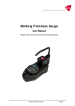
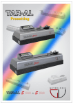
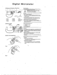
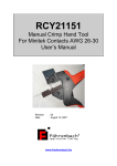
Digit Outside Micrometers
COMBIMIKE
User’s Manual
No.99MAA021A
SERIES No.159
Safety Precautions
To ensure operator safely, use this instrument in conformance with the directions and
specifications given in this User’s Manual.
Export Control Compliance
The goods, technologies or software described herein may be subject to National or
International, or Japanese Export Controls. To export directly or indirectly such matter
without due approval from the appropriate authorities may therefore be a breach of
export control regulations and the law.
!
[1] 1
The tip of the contact point on this micrometer is sharp. Handle it with care
so as not to scratch yourself.
CAUTION
M830
M865
IMPORTANT
• Do not use this instrument for a purpose other than measurement.
• Do not disassemble. Do not modify this instrument. It may damage the instrument.
• Do not use and store the micrometer at sites where the temperature will change abruptly.
Prior to use thermally stabilize the micrometer sufficiently at room temperature.
• Do not store the micrometer at sites where it will be exposed to dust and moisture.
• When using the micrometer in a position where it may be splashed directly with coolant, or
the like, apply rust prevention measures after use. Occurrence of rust can lead to
micrometer malfunction.
• Do not apply sudden shocks including a drop or excessive force to the caliper type outside
micrometer.
• Do not turn the thimble too quickly. Doing so may cause the counter to malfunction.
• Always perform zero setting prior to measurement.
• After use wipe off dust, cutting chips, and moisture from the instrument, then apply
rust-preventive oil to it.
Read the following text, referring to the illustrations at the left.
[1] Name of each part
1.
1. Frame 2. Anvil
3. Spindle
4. Sleeve 5. Friction thimble
6. Thimble 7. Thimble cap 8. Ratchet sleeve
9. Clamp
10. Counter
11. Cap
12. Wrench
2.
1. Frame 2. Cap
3. Screw Adjusting
5. Key, Screw 6. Gear
7. Ring, Clamp
4. Screw, Key clamp
8. Spindle
[2] Zero point adjustment
IMPORTANT
• Use a periodically inspected gauge block, standard for micrometer for zero point
[1] 2
[2] 1 (1)
[2] 1 (2)
adjustment, or master gauge block dedicated for the workpiece to adjust the zero
point of this instrument.
• Before zero point adjustment, thoroughly wipe the gage to be used and the
measuring face.
• Apply the same orientation and conditions for the zero adjustment and
measurement, following the steps below.
1. Where an indicated value on the counter is correct but the thimble shows a different
reading, perform the following adjustment.
(1) Where the zero point error is around ±0.01mm or less
Insert the supplied key spanner into a hole provided on the back of the sleeve's
reference line, and turn the sleeve to make the reference line aligned with the thimble's
zero line.
(2) Where the zero point error is ±0.01mm or more ~ M830 : Ratchet stop ~
<1> Loosen the ratchet stop with the supplied key spanner.
<2> Press the thimble to the outside (toward the ratchet stop) to allow it to move freely,
and align the thimble's zero line with the sleeve's reference line.
<3> Fasten the thimble by tightening the ratchet stop.
* Further, if the zero point is slightly misaligned, perform the adjustment of above item (1).
(3) Where the zero point error is ±0.01mm or more ~ M865 : Friction thimble ~
<1> Remove the thimble cap and loosen the pan-head screw with a precision screwdriver.
<2> Press the thimble to the outside (toward the thimble cap) to allow it move freely, and
align the thimble's zero line with the sleeve's reference line.
<3> Tighten the pan-head screw and make sure that the thimble is firmly fastened.
<4> Attach the thimble cap.
* Further, if the zero point is slightly misaligned, perform the adjustment of above item (1).
2. Where an indicated value on the thimble is correct but the counter shows a different value
from it, perform the following adjustment.
Refer to Figure [1] 2.
<1> Remove the cap.
<2> Turn the thimble while watching the inside through a hole and align the setscrew with
the hole position.
<3> Loosen the adjustment screw with a precision screwdriver, and, while holding the
adjustment screw by hand, turn the thimble to adjust the thimble's graduation line to the
counter value, then tighten the adjustment screw.
<4> Check the zero point and replace the cap.
Digit Outside Micrometers
[2] 1 (3)
COMBIMIKE
User’s Manual
No.99MAA021A
SERIES No.159
3. How to adjust a play in the spindle's rotation
Perform the following adjustment if the spindle has any play in its rotation. Refer to
Figure [1] 2.
<1> Remove the cap.
<2> Turn the thimble while watching the inside through a hole and align the key
clamp screw with the hole position, then tighten the clamp.
<3> Remove the key clamp screw using a precision screwdriver, lightly tighten the
key screw, then replace the key clamp screw.
<4> Loosen the clamp, and try to turn the spindle. Replace the cap when the spindle
smoothly rotates and has no play.
[4]
[3] How to measure
Counter
Scale, Thimble
Read the indicated value in the same way as that for zero point adjustment.
Perform measurement, keeping the same orientation and condition as when the zero
point adjustment was made.
[4] How to read
Scale, Sleeve
1. M830
(1) Case of reading the graduations (unit: mm)
The method of reading the graduations is as follows.
The minimum reading is 0.01 mm, however, it is also possible to read down to
0.001 mm by eye measure.
Reading on the Sleeve 7.
Reading on the Thimble .37
Total
7.37 mm
a: Sleeve
b: Thimble
<1> About
<2> About
(2)Case of reading the counter value (unit: inch)
0. 290”
[4] 1 (1)
+1µm
+2µm
2. M865
(1) Case of reading the graduations (unit: inch)
A micrometer with vernier has vernier graduations above the sleeve's reference
line.
The method of reading the graduations is as follows.
Reading on the Sleeve
Reading on the Thimble
Reading on the Vernier and Thimble
(2) Case of reading the counter value (unit: mm)
8.52 mm
[4] 1 (1)
<1>
0.325 “
0.010”
0.0006”
0.3356”
<2>
[6] Specifications
Instrumental error (20°C)
Operation Temperature
Storage Temperature
Standard accessory
[4] 1 (2)
[4] 2 (1)
[4] 2 (2)
Mitutoyo Corporation
Kawasaki, Japan
http://www.mitutoyo.co.jp
: ±2µm
±.0001”
: 5°C to 40°C
: - 10°C to 60°C
: Wrench (No. 301336)