1
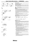
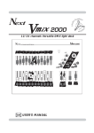
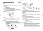
INSTRUCTION SHEET
MODEL H5678
BORING HEAD SET
NOTICE
Introduction
Anyone creating fine precision work will be glad to
use the Model H5678 Boring Head Set. This small,
precise set features a dial with graduations of
0.001" and 0.050" per revolution, sockets for 3⁄8"
boring bars, a 9⁄16" hole offset and a dovetail slide
with locking clamp. This set also comes with a fitted
wood case, Allen wrenches, 3 boring bars, and a
boring head with an MT#3 arbor.
The Model H5678 has three, 3⁄8" boring bar
placement options for making a wide range of hole
sizes.
1.
2.
3.
Hole A is used for smaller diameter holes.
Hole B is used for slightly larger diameter
holes.
Hole C is used for very large diameter
holes.
Installation of boring head into spindle can
be done with or without boring bar inserted
into the boring head.
To install the Model H5678 boring head:
1.
2.
3.
4.
5.
Turn off power to the machine.
Align the center of the hole to be bored to the
center of the spindle using an indicator or a
center finder.
Place the desired boring bar into the boring
head with the face of the boring bar aligned
with the travel of the boring head (Figure 2).
When everything is in the desired position,
tighten boring bar locking setscrew.
Install the boring head into the spindle.
Check a feeds and speeds chart for an
estimated starting point.
C
A
B
Figure 1. Boring bar hole placement.
Figure 2. Face of boring bar aligned with boring
head travel.
COPYRIGHT © NOVEMBER 2003 BY GRIZZLY INDUSTRIAL, INC.
WARNING: NO PORTION OF THIS MANUAL MAY BE REPRODUCED IN ANY SHAPE
OR FORM WITHOUT THE WRITTEN APPROVAL OF GRIZZLY INDUSTRIAL, INC.
PRINTED IN CHINA
Boring Head
Features
1.
The dial on this precision boring head reads
0.001" per index mark and 0.050" per
revolution. Note—This means if a 1.000"
hole has been bored with the dial at “0”, the
diameter of the bored hole will be 1.020" with
the dial at “2” (Figure 3).
Figure 4. Button head screw.
For your safety it is important to please follow
the warnings below:
Damage to your eyes, lungs, and ears could
result from failure to wear safety glasses, a
respirator and hearing protection while
using this machine. Make sure proper filter
is worn while wearing respirator.
Figure 3. Example of dial indexing.
2.
To help with the indexing adjustments, the
button head screw should be adjusted so
there is a small amount of drag on the ways.
When the dial is indexed to the desired
graduation, completly tighten the button
head screw. This will help in eliminating
chatter and vibration, while improving the
overall accuracy and finish of the bored hole
(Figure 4).
Loose hair and clothing
could get caught in
machinery and cause
serious personal injury.
Keep loose clothing
rolled up and long hair
tied up and away from
moving machinery.
Make certain your machine will accept
tooling. Failure to do so may result in
damage to tooling and machine. Always
turn spindle clockwise.