1
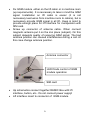
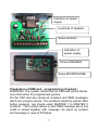
GSM LIFT COMMUNICATION SYSTEM GSM Lift Watch compact USERS GUIDE v2.0 1 The device has been designed for emergency call, for example from lift cabin to service department, police department, fire brigade. The setting as same as control is available remotely by SMS (short messages). After button pressing (activation) device dialling progressivelly phone numbers stored at SIM card of GSM module under names MASTER 1 to MASTER 5. In case of connection the rest of numbers is not dialled.The syste m returns to stand by mode after hang up of call by called number. Activation of device can be blocked by voltage leaded at galvanically isolated input DATA. Operation is indicated by internal sinalization.During activation is closed external output of signalization. Input DATA can be used for sending SMS with attention at failure of the lift. The device can be activated also by calling of GSM module (SIM card) number. The call will be accept only from number stored on SIM card as MASTER1 to MASTER5 (authorization). By this you can control state at the cabine of lift, make back call, etc– If you will use prepaid card the syste m automatically check the state of SIM card credit. At the moment of credit is under permitted level the syste m send SMS to preprogrammed number with information about low credit. This number you store on the SIM card as well. All parametres can be programmed frm mobile phone remotely by SMS. By SMS you can also control the device ( dialling of sent number ždoctor, ending of call, etc...) 2 The basic technical features: Power supply GSM network Ext.signalizaton 9 az 18V ss, 50 az500mA 900/1800MHz LED 12V or lamp 12V max.100mA Features: · After activation progressive call up to 5 numbers (MASTER1-5) stored on SIM card with call duration maximum 4 minutes · Back calling from MASTER numbers only stored on the SIM card · Check the credit at prepaid SIM cards with attention at low level by SMS message sent at preprogrammed number · Command SMS mode for remote control: o Change of MASTER numbers (progressivelly dialled numbers) ž the change can be performed from MASTER numbers only o Checking of GSM network (signal) o Checking of SIM card credit o Sending SMS with number which will be dialled by system Emergency call to unprogrammed numbers (under control of operator) servis etc. · · · · Input for call releasing ž possibility of call at failure only Input can be used for sending SMS with attention for failure of the lift (failure signal on the input must be longer than 2 minutes) automatic limiter of microphone amplifiering at the moment of connection to voice box possibility of dialling next number in order by pressing button 3 · sending programmable SMS during failure to preprogrammed number ž SMS is sending at change of state at input for time longer than 2 minutes GSM Lift Watch compact contents 3 parts: Acoustic module (microphone and speaker) (ReMic ) GSM module Lift interface 4 Installation: · Fix the REMIC box at lift cabin at the opposite place of button lift panel. For good acoustic quality we recommend fix it at level of the head. Befor REMIC box must be holes in button lift panel for microphone and speaker. Otherwise will be bad acoustic during a call! speaker and microphone is toward to lift button panel The fixing of REMIC box on the out cover of lift cabine (for example by screws) 73 30 o4 125 5 · · Fix GSM module either on the lift cabin or in machine room (up requirements). It is neccessary to take in mind the GSM signal. Installation on lift cabin is easier (it is not neccessary lead wires from machine room to cabine), but is neccessary provide GSM signal in all lift.. Keep in mind to provide enough place for lift interface for manipulaton with SIM card. Screw up connector of antenna cable. When connect magnetic antenna put it on the iron place (subject). On this subject depends quality of receiving GSM signal. The bad antenna position can caused interferences during a call. At this case change antenna position. Antenna connector LED Diods control of GSM module operation SIM card · · Up schematics connect together REMIC Box with lift interface, button, etc.. Do not connect power supply! Lift interface insert to connector of GSM module. 6 Indication of power supply Loudness of speaker Screw terminal Indication of power supply Screw SPEAKER Screw MICROPHONE Preparation of SIM card é programming of system : WARNING: The syste m means that on SIM card will be stored only information for programmed system. On the SIM card are stored all numbers and SMS messages which are using by device. The numbers called by syste m after button pressing are stored under MASTER 1 to MASTER 5 numbers . The number where is sent SMS message about low credit is stored together with message. As same as number and message in case of lift failure. 7 · Insert SIM card to mobile phone which you will use for programming. · Set switch on without PIN (if you have version of SIM with fix PIN, program the PIN and switch on with PIN). · To phone book stoe phone numbers, which will be called , under names MASTER1– Numeral after MASTER name determine order of called number. Of course store only so many MASTERx how many you need (example MASTER1 only). Attention! All types must be big! · When are on the SIM card stored SMS messages erased them. · Store on the SIM card requested SMS message with phone number where will be sent at the moment of low credit of SIM. This message must be stored in list of messages as 1! When is SMS not stored ž not sending. · As secod SMS message store on the SIM card requested SMS with phone number , where will be sent at the moment of lift failure (input DATA). When is SMS not stored ž not sending. · Switch of the phone and take out the SIM card. Note: During work with mobile phone progress up user manual of corresponding mobile phone. The SMS messages (mentioned above) are storing at almost mobile phone producers as unsent messages. Operation: · · · · · Insert SIM card. (When you press yelow button the SIM card keeper is released). Connect power supply. The green LED on GSM module light up as same as red LED on lift interface and red LED on REMIC Box. After a few seconds the red LED on GSM module flash 3x times shortly and start flashing in period of 2 seconds. The red LED on GSM module flashing quickly ž log to GSM network. 8 · · · · · · · The red LED on GSM module flashing in period of 2 seconds again ž stand by mode. Wait for cca 30 seconds and device is ready for operation. Press button (call must not be blocked ž via input DATA): The red LED on GSM module flashing quickly (calling to preprogrammed numbers). Progressively are called numbers stored on the SIM as MASTERx (up the call is not accepted). In speaker you can hear signals of GSM network (searching of opposite side, ringing tone, etc.). When call is accepted by called side, then is establish connection with lift cabin. When you now press button again then will be dialled next MASTERx in order. By hang up of call on mobile phone is connection ended. The connection is also ended automatically after 4 minutes. Make call from various MASTER number to device: Your call will be accepted and you can speak with person in lift cabin. By hang up is connection ended. Make call from UNMASTER number. The call will be ignorated. In case of low credit is after call ending sent SMS to corresponding preprogrammed number. Test sending of SMS at the moment of lift failure. (failure signal on input DATA must be longer than 2 minutes) 9 Remote control and setting by SMS All parametres you can control and programm remotely by SMS. The SMS are accepted from numbers MASTER 1 to MASTER 5 stored on the SIM card. The SMS from another number are accepted but immediatelly erased. Command SMS must be written always by BIG TYPES and contens 2 parts separated by comma. Command body Identificator MASTERx CAL CAL , , , +420603123456 ATD603123456; AT+CSQ Identificator MASTER is determined for work directly with phone numbers of emergency call (rewriting, erasing, adding). CAUTION! When you use it for numbers erasing be carefull to stay min. 1 MASTER number in list otherwise you cant use remote control of syste m. Identificator CAL is determined for general commands of TC 35 GSM modules. There are more difficult and unqualified using can cause a problems. 10 dentfd.p A STER1p arcp - p5p,p p om b b rtepy m exp hp a)m tnptMb y ncp+ p A STER1p LSDp - p5p,p hp p hp SEv 36g- 0g2,3; nlrb asnp A STER1- h4206360- 0 g- - - p A STER10hp LSDhSEv 36g- 0g2,3; LSDp LSDp hp SEP p hp SE4LkSTp LSDhSEP p LSDhSE4LkSTp LSDp hp SE4LTGp LSDhSE4LTGp LSDp hp SE4LSLA F p LSDhSE4LSLA F p LSDp hp SE4LSA A F p LSDhSE4LSA A F p LSDp hp SE4LkU1"arcp LSDhSE4LkU1"- p LSDp hp SE4LLDN"F p LSDhSE4LLDN"F p enuocdafdm tpm .p.nrfMcnp reepm cpo)rtCnptMb y ncpm tpam udfdm tparcp ncrudtCptMb y ncpm tpam udfdm tparcpp enwdonporsspdb b nedrfnssxpr.fncpTA TpcnondwdtCpfm pacnacm Ccrb b ne 0 ptMb y nc+ pS.fncpntenepm .porsspenwdonpcnfMctupTA Tp: df)pb nuurC nOp KNppppppppppppppppp5pom ttnofdm tp: rupb renp IKpLS11BR1pppp5porssneparcfpdupMtcnro)ry snp UYTHppppppppppppp5py Muxp enwdonportonsspacnuntfpom ttnofdm t L)noQpf)npenwdonpufrfMu p1nfMctnepTA Tpdtp.m cb Op 4LkSTOp6pp5ppufrtepy xp 4LkSTOpgp5pum b nm tnpduporssdtCpfm penwdonp 4LkSTOp2p5penwdonporssdtCpp L)noQpm .p7TA pudCtrspp 1nfMctnepTA Tpdtp.m cb Op4LTGOp- 9h((p am : ncpm .pudCtrsp?b rlpg0+p b dt pwrsMnpdup- 9p?nlrb asnp- 9h((+p g L)noQpm .pocnedfpsnwnsp?rfpacnardeporceu++ p 1nfMctnepTA Tppp4LSLA Op6- =S66p g L)noQpm .pb rldb Mb pocnedfpsnwns+ p 1nfMctnepTA Tppp4LSA A Op66==2Sp L)noQpf)npA STER1ptMb y ncpm tp pam udfdm tparcp 1nfMctnepTA Tpu)m : upam udfdm thptMb y ncp prteptrb nppMtencpdfupdupufm cnepm tpf)npTBA p 4LkU1Op- h4206360- 0g- - - h- 2,hA STER1- p E)npufrfnpm .posm oQpdtpenwdon 1nfMctnepTA Tpp4LLDNO/66 6- 6- h6- O- 9Og3 p Time of device operation Note: This is a part of commands. All commands via manual GSM module Siemens TC35. Principally (capacity of buffer in CPU) is impossible use commands of TC35 its reply is longer than 32 (except phone number) digits. In this case SMS isnt return ž command is ignorated. 1 ) Regards CLIP the phone number must be in international form (+420– – ) 2 ) in case of present call on device, is hang up and device call to another number (sent in SMS). 3 ) numbers are in hexadecimal form. 11 Trouble shooting: No LED lighting. Wrong power supply. Check power supply and its polarity. Did not happen quick “ log flashing of red LED Module is not log on the net: · wrong SIM card ( or bad put to holder) · old 5V SIM card (module supports cards for 3V and lower) · set log on the GSM with PIN · so weak GSM signal Nothing happened when you press the button. On the SIM card are not stored MASTERx phone numbers . Leaded block voltage to input DATA. 12 Switch of jumper Indication LED Switch on jumper Indication by lamp Power supply ATTENTION ON POLARITY lift cabin 12V polarity up indication 12V for blocking (not depends on polarity) 13 Alphatech spol. s r.o. Jeremenkova 88 140 00 Praha 4 tel. 272 103 335, fax. 272 103 334 e-mail: [email protected] internet: http://www.alphatech.cz nas e souradnice GPS (WGS 84) N 50°02¢35.5² E 14°25¢42.0² 18.1.2003 14