1
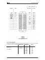
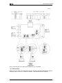
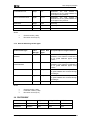
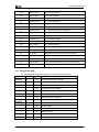
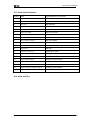
Citect for Windows
Driver Specification
MooreP Driver
Author
Date
Comment
Vasu Raman
28/6/96
Original
Bruce Kinchin
1/5/97
Revised for Front-end / Back-end
JO Reyes
26/7/01
Minor updates to doco
Driver Design Specification
Contents
1.
TARGET DEVICE(S) AND PROTOCOL
4
1.1
Introduction
4
1.2
Device Manufacturer
4
1.3
Device Definition
4
1.4
Communications Method
4
1.5
Communications/Hardware Configuration
4
1.5.1
Wiring Diagrams
5
1.5.2
I/O Device Settings
6
1.5.3
Software Setup
8
1.6
Special Requirements
9
1.7
Maximum Request Length
9
2.
USER INTERFACE
10
2.1
Introduction
10
2.2
Driver Name
10
2.3
Boards Form
10
2.3.1
Board Type
10
2.3.2
Address
10
2.3.3
IO Port
10
2.3.4
Special Opt
10
2.4
Ports Form
10
2.4.1
Baud Rate
10
2.4.2
Data Bits
10
2.4.3
Stop Bits
10
2.4.4
Parity
10
2.4.5
Port Number
10
2.4.6
Special Opt
10
2.5
IO Devices Form
11
2.5.1
Protocol
11
2.5.2
Address
11
2.6
Pulldown lists Help
11
2.7
IO Device Variable Types
11
2.7.1
ICI variable types
11
2.7.2
General addressing variable types
12
2.8
PROTDIR.DBF
MOOREP_E.DOC
12
2
Driver Design Specification
2.9
Parameters and INI options
13
2.9.1
Standard Parameters
13
2.9.2
Driver Specific Parameters
13
2.10
Driver Specific Errors
13
2.11
Driver Error Help
14
2.12
Debug Messages
15
2.13
Stats Special Counters
16
2.14
Hints and Tips
16
REFERENCES
17
3.1
References
17
3.2
Contacts
17
3.
4.
APPENDIX A - ABBREVIATIONS AND DFINITIONS
18
4.1
Abbreviations
18
4.2
Definitions
18
MOOREP_E.DOC
3
Driver Design Specification
1. Target Device(s) and Protocol
1.1 Introduction
This driver interfaces Citect to the MYCRO Model 320 Independent Computer Interface (ICI). The
Model 320 ICI allows the computer to communicate and share data with any device on the Local
Instrument Link (LIL). The Model 320 ICI has two versions BBA and BCA. Version BCA is newer and
has three new commands. This driver will support version BCA only.
The LIL is a communication network which connects a group of stations such as Model 351 TripleLoop Digital Controller (TLDC), Model 352 Single-Loop Digital Controller (SLDC), Model 321
Expansion Satellite (LES), Model 324 Programmable Sequence Controller (PSC), Model 382 Logic
and Sequence Controller (LSC), and Model 383 Multi-Point Display Station (MDS).
This driver will be based on the Front-end / back-end driver model. This is due to the relatively slow
communications and also to give the driver the ability to handle either setting of the ‘Link
Acknowledge Delay’.
This driver will not handle unsolicited requests or records at this stage, although the architecture of
the front-end/back-end design will make future inclusion possible.
1.2 Device Manufacturer
Moore Products Co.
1.3 Device Definition
Model 320 ICI allows the computer to communicate with any device on the LIL using the serial ports.
1.4 Communications Method
The ICI is based on the RS-232C serial data communication standard. The ICI is also optionally
configurable for a RS-422 asynchronous version.
1.5 Communications/Hardware Configuration
Detailed diagrams and tables are available in the ICI User's Manual.
MOOREP_E.DOC
4
Driver Design Specification
1.5.1 Wiring Diagrams
MOOREP_E.DOC
5
Driver Design Specification
1.5.2 I/O Device Settings
Switch/Jumper settings are required for selecting serial port configuration, baud rate, link address,
transmission method. The default settings for the ICI are as follows:
Default Value
Switch/Jumpe
Setting
r
Serial Port Board
Data Format
8 data bits
SW2-8
OFF
NO parity
SW2-4
ON
Link Address
1
SW2-2
ON
SW2-1
ON
SW1-8
ON
SW1-4
ON
SW1-2
ON
SW1-1
ON
MOOREP_E.DOC
6
Driver Design Specification
Port Configuration
Computer Port Baud Rate
Diagnostic Port Baud Rate
MPU Baseboard
Transmission Method
Link Acknowledge Delay
Null-filled Data
Send Command Security
Cable Adapter Board
DS CTS Line Select
DS CTS Line Select
MOOREP_E.DOC
RS-232C
W5
W6
W7
W8
2-3
2-3
3-12
2-7
Binary
Enabled
Enabled
None
SW5
SW4
SW3
SW2
SW1
ON
OFF
OFF
ON
ON
DTR
DSR
W1
W2
4
4
9600
9600
7
Driver Design Specification
Refer to the Model 320 LIL ICI User's Manual Appendix L for more details.
1.5.3 Software Setup
Stations on the LIL have to be configured by the user using the Configuration Management Software
supplied by Moore Products Co. (Details not available - Test hardware was pre-configured)
MOOREP_E.DOC
8
Driver Design Specification
1.6 Special Requirements
None.
1.7 Maximum Request Length
256 bytes.
MOOREP_E.DOC
9
Driver Design Specification
2. User Interface
2.1 Introduction
This section defines how the user will see the driver. This relates directly to how the Citect forms
need to be filled out and any special INI options. For the kernel, the debug trace messages and the
Stats.Special counters are documented.
2.2 Driver Name
MOOREP
2.3 Boards Form
2.3.1 Board Type
COMX
2.3.2 Address
0
2.3.3 IO Port
Not used.
2.3.4 Special Opt
Not used.
2.4 Ports Form
2.4.1 Baud Rate
Can be set to 300, 1200, 2400, 4800, 9600, 19200, or 38400.
2.4.2 Data Bits
Can be set to 7 or 8. This should be set to 8 as this is the default for the ICI.
2.4.3 Stop Bits
1
2.4.4 Parity
Can be set to Even, Odd, or None. This should be set to None as this is the default for the ICI.
2.4.5 Port Number
COM port number to which ICI is attached.
2.4.6 Special Opt
Not used.
MOOREP_E.DOC
10
Driver Design Specification
2.5 IO Devices Form
2.5.1 Protocol
MOOREP1
MOOREP2
MOOREP352
MOOREP382
MOOREP383
for the ICI
for general addressing independent of Model.
for future use (Model 352 SLDC)
for future use (Model 382 LSC)
for future use (Model 383 MDS)
2.5.2 Address
H.L.S
where
H
L
S
Any number from 0 to 31 is a valid Hi-Level Link Address.
Any number from 0 to 4 is a valid Link Number.
Any number from 1 to 64 is a valid LIL Station Address.
For example, 1.2.5 would refer to Station address 5, on Link number 2, on Hi-Level Link 1.
2.6 Pulldown lists Help
The following entries should be included in the Citect Help.DBF spec file.
TYPE
DATA
FILTER
PROTOCOL
MOOREP1
PROTOCOL
MOOREP2
2.7 IO Device Variable Types
The protocol may communicate with many different types of devices on the Local Instrument Link.
Variables within each type of device can be accessed using a generic addressing format provided by
the protocol, however specific addresses have certain meanings for each type of device. For
example, the Model 352 Loop controller has a variable “Proportional Gain” which is stored in channel
6, parameter 2 of the unit. To avoid the user of Citect having to know this, additional driver
specification files (driver.dbf) are created for each case in addition to the general addressing scheme.
Also, The ICI unit behaves as any other station on the LIL. It contributes channels to the LIL global
database. However, the information available in the ICI is accessed differently, or may be specific to
the ICI and not available in normal stations on the LIL. In this case a separate DBF is provided for the
ICI itself.
2.7.1 ICI variable types
IO Device Type
MOOREP_E.DOC
Citect
data type
Citect data
format
Description/Special Usage/Limitations
11
Driver Design Specification
Local channel in ICI
Integer
LCx
Read/Write. The local channel is
contributed to the LIL global database by
the ICI approx every 0.5secs.
Bit in local channel in ICI
Digital
LCx.z
Read/Write. The local channel is
contributed to the LIL global database by
the ICI approx every 0.5secs.
Status word
Integer
STW
Read Only.
Status bits
Digital
STWz
Read Only.
Where
x
z
Channel number (1-256)
Bit number in word (0-15)
2.7.2 General addressing variable types
IO Device Data Type
Citect
data type
Citect Data
types
Description/Special Usage/Limitations
Channel from LIL Global
database
Integer
Cx
Read/Write. This datatype is the first
parameter of the channels contributed to
the LIL global database approx every
0.5secs.
Bit in channel from LIL
Global database
Digital
Cx.z
Read/Write. This datatype is the first
parameter of the channels contributed to
the LIL global database approx every
0.5secs.
Parameter
Integer
CxPy
Read/Write. Parameters not part of the
LIL global database are accessed through
this datatype.
Bit in parameter
Digital
CxPy.z
Read/Write. Parameters not part of the
LIL global database are accessed through
this datatype.
Where
x
y
z
Channel number (1-256)
Parameter number (1-256)
Bit number in word (0-15)
2.8 PROTDIR.DBF
TAG
FILE
BIT_BLOCK
MAX_LENGTH
OPTIONS
MOOREP1
MOOREP
2048
2048
0x03
MOOREP2
MOOREP
2048
2048
0x03
MOOREP_E.DOC
12
Driver Design Specification
2.9 Parameters and INI options
2.9.1 Standard Parameters
Block
Delay
MaxPending
Polltime
Timeout
Retry
WatchTime
256
0
2
20
1000
1
30000
2.9.2 Driver Specific Parameters
[MOOREP]
LocalICIChannelAmount
On startup, a command is sent to the ICI detailing the number of
channels the ICI will contribute to the LIL database. Default=6
If defined, a command is sent to the ICI on startup setting the
Watchdog time.
WatchDog
2.10 Driver Specific Errors
The following errors are listed in Appendix D of the LIL ICI manual.
Driver Error Code
Mapped to
(Hexadecimal)
(Generic Error label)
Meaning of Error Code
50
No_Buffers
Record request buffer not empty
51
Invalid_Data
Data not ready
52
No_Buffers
Input buffers not empty
53
General_Error
Unsolicited record available
54
Unit_Offline
LIL interface offline
55
Cannot_Read
Read not supported this UnitType/Command
80
Unit_Timeout
Timeout between characters
81
Invalid_Data_Fmt
Invalid data or bad character
82
Invalid_Command
Invalid command
83
Invalid_Command
Invalid request
84
General_Error
Word count error
85
General_Error
Checksum error
86
Msg_Overrun
Message overflow
87
General_Error
Parity or framing error
88
General_Error
Transfer prevents command execution
89
General_Error
Station not in global database
8A
Invalid_Data
Data not available
8B
No_Buffers
Local link buffers full
8C
General_Error
Global database not ready
MOOREP_E.DOC
13
Driver Design Specification
8D
Unit_Timeout
Link command timeout
90
General_Error
LIL - Link not present
91
Hardware_Error
LIL - On-Board Dual-Port RAM failure
92
Hardware_Error
LIL - Local RAM failure
93
Hardware_Error
LIL - ROM check failure
94
Hardware_Error
LIL - Link physical interface failure
97
Hardware_Error
LIL - Off-Board Dual-Port RAM failure
99
Hardware_Error
ICI - Buffer RAM failure
9A
Hardware_Error
ICI - Local RAM failure
9B
Hardware_Error
ICI - ROM check failure
9C
Hardware_Error
ICI - Piggyback board failure
9D
Unit_Timeout
ICI - Receive timeout
9E
Unit_Timeout
ICI - Transmit timeout
A1
General_Error
Transmission problem, command not received
A2
No_Buffers
Destination buffers full, command not received
A3
Unit_Offline
Destination station offline, command not sent
A4
Unit_Offline
Gateway offline, command not sent
A5
General_Error
Link command checksum error, command not sent
2.11 Driver Error Help
The following entries should be included in the Citect ProtErr.DBF spec file.
PROTOCOL
MASK
MOOREP
0
50
Record request buffer not empty
MOOREP
0
51
Data not ready
MOOREP
0
52
Input buffers not empty
MOOREP
0
53
Unsolicited record available
MOOREP
0
54
LIL interface offline
MOOREP
0
55
Read not supported this UnitType/Command
MOOREP
0
80
Timeout between characters
MOOREP
0
81
Invalid data or bad character
MOOREP
0
82
Invalid command
MOOREP
0
83
Invalid request
MOOREP
0
84
Word count error
MOOREP
0
85
Checksum error
MOOREP
0
86
Message overflow
MOOREP
0
87
Parity or framing error
MOOREP_E.DOC
ERROR
MESSAGE
14
Driver Design Specification
MOOREP
0
88
Transfer prevents command execution
MOOREP
0
89
Station not in global database
MOOREP
0
8A
Data not available
MOOREP
0
8B
Local link buffers full
MOOREP
0
8C
Global database not ready
MOOREP
0
8D
Link command timeout
MOOREP
0
90
LIL - Link not present
MOOREP
0
91
LIL - On-Board Dual-Port RAM failure
MOOREP
0
92
LIL - Local RAM failure
MOOREP
0
93
LIL - ROM check failure
MOOREP
0
94
LIL - Link physical interface failure
MOOREP
0
97
LIL - Off-Board Dual-Port RAM failure
MOOREP
0
99
ICI - Buffer RAM failure
MOOREP
0
9A
ICI - Local RAM failure
MOOREP
0
9B
ICI - ROM check failure
MOOREP
0
9C
ICI - Piggyback board failure
MOOREP
0
9D
ICI - Receive timeout
MOOREP
0
9E
ICI - Transmit timeout
MOOREP
0
A1
Transmission problem, command not received
MOOREP
0
A2
Destination buffers full, command not received
MOOREP
0
A3
Destination station offline, command not sent
MOOREP
0
A4
Gateway offline, command not sent
MOOREP
0
A5
Link command checksum error, command not sent
2.12 Debug Messages
MOOREP_E.DOC
15
Driver Design Specification
2.13 Stats Special Counters
Number
Label
Purpose/Meaning of this counter
0
TX
Number of messages transmitted
1
RX
Number of messages received
2
BAD CRC
Bad Checksum
3
BAD RSW
Bad RSW
4
DATA NOT READY
Data is not ready
5
DATA IN CACHE
Data is not in cache
6
DATA IN CACHE BUT OLD
Data is in cache but old
7
DATA NOT IN CACHE
Data is not in cache
8
BAD CACHE UPDATE",
Bad cache update
9
CACHE UPDATE ATTEMPT
Cache update attempt
10
BAD LENGTH
Bad length
11
BAD FLAG
Bad Flag
12
ADDING CACHE QUE
Adding cache queue
13
READING CACHE QUE
Reading cache queue
14
BUILD CMD CACHE
Building command cache
15
BUILD CMD NORMAL
Building command normal
16
REPLY FROM CACHE
Replying from cache
17
ALLOC CACHE ELEMENT
Allocating cache element
18
INVALIDATING CACHE ELEMENT
Invalidating cache element
19
BAD STATE
Response bad state
2.14 Hints and Tips
MOOREP_E.DOC
16
Driver Design Specification
3. References
3.1 References
Model 320 Local Instrument Link Independent Computer Interface User's Manual
3.2 Contacts
Vasu Raman
CSE Technology Pty Limited
Level 5
7-9 Merriwa Street
Gordon NSW 2072
Australia
Tel: (02) 9418 2611
Fax: (02) 9418 2633
Email: [email protected]
Bruce Kinchin
Ci Technologies Pty Limited
10-12 West Street
PO Box 174
Pymble NSW 2073
Australia
Tel: (02) 9855 1000
Fax: (02) 9488 9164
Email: [email protected]
Rodney Strouch
Rod White
Craig Linguard (0418) 609235
Stephen Burke (MD)
Moore Products Co. (Australia)
Unit 27, 198 Young Street
Waterloo, NSW 2017
Australia
Tel: (02) 9319 4877
Fax: (02) 9318 1743
Technical Information Centre
Singapore phone: +65 299 6051
USA phone: +1 215 646 7400, Ext 4842
BBS: +1 215 2834968
Web: http://www.mpco.com
MOOREP_E.DOC
17
Driver Design Specification
4. Appendix A - Abbreviations and Dfinitions
4.1 Abbreviations
4.2 Definitions
The following terms used throughout the remaining sections have the following meanings:
LIL— The MYCRO Local Instrument Link which provides a means of communication between stations
connected to the LIL.
ICI— The Model 320 LIL Independent Computer Interface which consists of the Local Instrument Link
Computer assembly and the interface assembly and operates as a station on the MYCRO Local
Instrument Link.
MOOREP_E.DOC
18
Driver Design Specification
LES— The Model 321 LIL Expansion Satellite which provides a means of communications between
elements on the Hi-Level Link and stations on the Local Instrument Link and/or expands the LIL from
32 stations to 64 stations maximum.
PSC— The Model 324 Programmable Sequence Controller which primarily performs discrete logic
and sequencing functions with batch sequencing language capabilities.
SLDC— The Model 352 Single-Loop Digital Controller which primarily performs regulating control
functions.
LSC— The Model 382 Logic and Sequence Controller which primarily performs discrete logic and
sequencing functions.
MDS— The Model 383 Multi-Point Display Station which provides local indication and alarming along
with digital communication capabilities.
Link Interface Board— A circuit board assembly of the ICI which communicates with other devices of
the LIL system (SLDC's, PSC's, etc.) over the Local Instrument Link.
Serial Port Board— A circuit board assembly of the ICI which communicates with the user's computer
over the RS-232C link.
MPU Base Board— A circuit board assembly of the ICI which contains the microprocessor and
associated components.
Station— Any stand-alone hardware element that resides on a Local instrument Link, such as a
Single-Loop Digital Controller, Programmable Sequence Controller, ICI. Local Expansion Satellite,
etc.
Channel— An addressable data element in a station connected to the LIL. Each LIL station may
generate up to 256 channels.
Parameter— One of up to 256 data addresses associated with each channel that can be addressed by
other LIL stations. The first parameter of each existing channel is updated periodically to the LIL in
the global database.
Command— The transmission generated by the user's computer and sent to the ICI for the purpose of
requesting or sending data.
Response— The returned data from the interface to the user's computer.
Computer— The user's general purpose computer which is connected to the ICI.
MOOREP_E.DOC
19