1
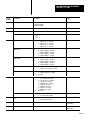
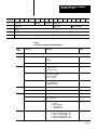
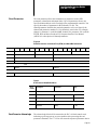
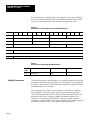
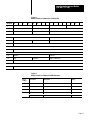
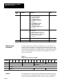
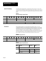
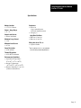
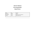
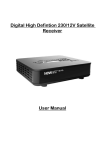
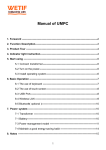
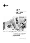
Allen-Bradley
Loop Controller Interface Module
(Cat. No. 1771-LIA)
Product Data
The Loop Controller Interface Module (Cat. No.
1771–LIA) allows PLC–2, PLC–3 and PLC–5
family programmable controllers to
communicate with Moore Products Model 352
single–loop PID controllers via the Model 320
Independent Computer Interface.
Introducing the Loop
Controller Interface
Module
The loop controller interface module receives generic and controller specific
commands from the Programmable Controller (PC) and interprets, verifies, and
processes them by generating the necessary link to the loop controllers. The
1771–LIA module can communicate with up to 31 loop controllers through an
RS–422 serial link.
The Loop Controller Interface Module can:
monitor/change setpoint, valve, and operating mode, and acknowledge, set,
reset alarms
define station address/loop numbers for status reporting to the programmable
controller
examine/change PID parameters, alarm points, and output limits
transfer configuration to a loop controller, programmable controller, or
receive a configuration from a programmable controller.
Publication 1771-2.141 - June 1989
PN 955104-98
Loop Controller Interface Module
(Cat. No. 1771-LIA)
Description of the Loop
Controller Interface Module
The Loop Controller is shown in figure 1. Interface Module commands are
shown in table A.
Figure 1
Loop Controller Interface Module (Cat. No. 1771–LIA)
Table A
Loop Controller Interface Module (1771–LIA) Commands
Page 2
FUNCTION
COMMAND
CODE
RESPONSE
Change the setpoint, output, operating mode, acknowledge, enable,
disable alarms
SET CONTROL
01H
LOOP STATUS
Examine PID parameters, alarm limits, and output limits
READ PARAMETER
02H
READ PARAM ACK
Change PID parameters, alarm limits and output limits
MODIFY PARAMETER
03H
MOD PARAM ACK
Transfer a configuration from a station to a 1771-LIA
UPLOAD
04H
UPLOAD ACK
Transfer a configuration from a 1771-LIA to a station
DOWNLOAD
05H
DOWNLOAD ACK
Transfer a configuration from a 1771-LIA to a PC
READ CONFIG
06H
READ CONF ACK
Transfer a configuration from the PC to the 1771-LIA
WRITE CONFIG
07H
WRITE CONF ACK
Sends an ICI command to the ICI
ICI COMMAND
08H
ICI ACK
Loop Controller Interface Module
(Cat. No. 1771-LIA)
Compatibility
The user must be familiar with the terminology, configuration and operation of
Moore Products Model 352 Single Loop Digital Controller (SLDC) and Model
320 Independent Computer Interface (ICI). Depending on the application, you
must also be familiar with Moore Products Model 321 Local Expansion
Satellite (LES).
Proper operation of the Loop Controller Interface Module depends upon correct
setup of the Model 320 ICI. Set the ICI as follows:
Parameter
Setup
Switch Location
ICI link address
(see note)
serial board SW1, 2
Baud rate
9600
serial board W7
RS-232-C/RS-422
RS-422
serial board W5, W6
Transmission method
Binary
MPU board SW5 closed
Link Acknowledgement Delay
Enabled
MPU board SW4 open
Null filling
Enabled
MPU board SW3 open
Send command security
Disabled
MPU board SW1, 2
Format
1 start, 8 data, 1 stop,
no parity
SW2 - 8 off, SW2 - 4 on
Note: The 1771-LIA provides an interface with up to 61 Moore Products 352 controllers, depending on the Moore hardware
configuration.
Refer to Moore Products publications AD320-10 (Local Instrument Link Computer Interface User's Manual), AD352-10
(MYCRO 352 Single Loop Digital Controller User's Manual) and AD321-40 (Model 321 Expansion Satellite Link Interface
Communication User's Manual).
Page 3
Loop Controller Interface Module
(Cat. No. 1771-LIA)
Installing the Loop
Controller Interface
Module
In this section we tell you how to initially handle your loop controller interface
module, key your I/O chassis, install your your module and make your wiring
connections.
Initial Handling
ATTENTION: Remove power from the 1771 I/O chassis
backplane and wiring arm before removing or installing the loop
controller interface module.
Failure to remove power from the backplane or wiring arm could cause
module damage, degradation of performance, or injury.
Failure to remove power from the backplane could cause injury or equipment
damage due to possible unexpected operation.
The loop controller interface module contains components which can be
damaged by electrostatic discharge. The module is shipped in an electrostatic
shielded bag for protection. Follow the handling procedures outlined below to
guard against damage to your module.
ATTENTION: Under some conditions, electrostatic discharge can
degrade performance or damage the module. Read and observe the
following precautions to guard against electrostatic damage.
Touch a grounded object to discharge yourself before handling the module.
Do not touch the backplane connector or connector pins.
If you configure or replace internal components, do not touch other circuit
components inside the module. If available, use a static–safe work station.
When not in use, keep the module in its static–free shield bag.
Keying the I/O Chassis
Use the plastic keying bands, shipped with each I/O chassis, to key your I/O
slots to accept only this type of module. Place the keying bands on the chassis
backplane between:
12 and 14
16 and 18
Page 4
Loop Controller Interface Module
(Cat. No. 1771-LIA)
Slots on the rear edge of the circuit board (figure 1) are matched to these slots to
allow insertion of this type of module. You can key any connector in an I/O
chassis to receive this module except for the left–most connector reserved for
adapter or processor modules.
Inserting the Module Into the Chassis
Connecting the Loop
Controller to the Module
1.
Position the module so that the circuit board on the rear of the module
lines up with the top and bottom card guides in the chassis.
2.
Slide the module into the chassis.
3.
Press firmly to seat the module in the chassis backplane connector.
4.
Swing the module locking latch down into place over the front edge of the
module.
You make connections to the module through the 1771–WA field wiring arm.
The arm pivots on the I/O chassis to connect with terminals on the front of the
module and acts as a terminal strip. The wiring arm allows the module to be
removed from the chassis without disconnecting wiring.
Make certain all power is removed from the module before making wiring
connections.
1.
Swing the wiring arm up into position on the front of the module. The
locking tab on the module will secure it into place.
2.
Make your connections to the field wiring arm as shown in figure 2. (Use
the label on the front of the wiring arm to identify your wiring.)
NOTE: Use twinaxial cable (cat. no. 1770–CD), or an equivalent shielded
twisted–pair cable with a minimum impedance of 60 ohms and a maximum
capacitance of 75pF per meter, for the serial link. Do not exceed 4000 ft.
Page 5
Loop Controller Interface Module
(Cat. No. 1771-LIA)
Figure 2
Preparing the Connecting Wiring
3.
Refer to figure 2. Strip 2 inches of the outer insulation from the cable end
which will connect to the wiring arm.
4.
Remove exposed foil.
5.
Strip 3/8 inch of insulation from the end of each wire.
6.
Connect the wires to the swing arm as shown in figure 3.
ATTENTION: The field wiring arm terminal identification
number is not the same as the number of the bit which controls that
output.
Page 6
Loop Controller Interface Module
(Cat. No. 1771-LIA)
Figure 3
Wiring the Loop Controller Interface Module and the Model 320
Independent Computer Interface
A
0
1
2
3
4
5
6
7
8
B
Allen-Bradley
Programmable
Controller
(PC)
Block Read
Response
1771 I/O Chassis
Moore Model 352 Loop Controllers
LIA Controller
Comm Adapter
Block Write
Command
RS422
–––––––
1771–
Field Wir
Moore Model 320
Independent
Computer
Interface (ICI)
31 maximum
Local Instrument Link (LIL)
1771-LIA
Wiring Arm
5
4
A
0
Model 320 ICI
Wiring Strip D
1
2
3
4
7
8
9
10
Page 7
Loop Controller Interface Module
(Cat. No. 1771-LIA)
Programmable Controller
Data Table Requirements
You must allocate two blocks of memory within the programmable controller’s
data table for use by the interface module. The module requires this memory for
block transfer read and write files. Refer to the appropriate programmable
controller user’s manual for information on how to set up the data table.
The maximum length of the block transfer write (BTW) file is 64 words. Set the
length of the write file to the default value of 00.
The maximum length of the block transfer read (BTR) file is 64 words. Set the
length of the read file to the default value of 00.
Setting the length of the files to the default value of 00 allows the module to
determine the proper file length.
You will also need to allocate portions of the data table for the files related to
the module’s commands.
Set Control Command
The Set Control command is used to supply basic control and status command
changes to one or more loop controllers connected to the local instrument link
(LIL). It also determines what information is returned in LOOP STATUS. A
single set control block may be used to address up to 12 loops. Multiple set
control commands must be used to address more than 12 loops. The set control
command enables the programmable controller to:
select the operating mode of the SLDC
enter the value of a new setpoint or valve
enable and acknowledge alarms
select SLDC status information
The programmable controller sends the set control command to the LIA module
via block transfer write instructions. The module interprets the command and
sends the appropriate message out to the loop controller over the RS–422 serial
link through the ICI.
Important: The loop controller must be in the manual mode to change a valve.
The loop controller must be in automatic mode when changing a setpoint.
Word 1 of the set control file (figures 4 and 5) is the block header. This word
indicates the beginning of the set control file.
Word 2 identifies the page and loop segment selected. The page number (in hex)
is used to identify this particular set control command and its status. Loop
segment data bits allow the user to select which loop segment is to be executed
for this particular set control command.
Page 8
Loop Controller Interface Module
(Cat. No. 1771-LIA)
Word 3 contains the data and number of loops information. The data bit value
identifies the data type being sent. Data is in BCD or binary. Number of loops
identifies how many loop segments are being used by this set control command.
Word 4 is reserved for future use.
Word 5 is used to identify the physical station address and loop being accessed,
and whose status is being returned. Note: If this loop segment data bit is not set,
status will still be returned for this station loop (see word 2 above).
Word 6 contains the bits that enable, disable or acknowledge alarms. Refer to
figure 5 for an explanation of these bits.
Word 7 determines if a new setpoint or valve value will be sent for this loop
segment. Word 7 also contains the loop control bits, which control the operating
conditions for this station/loop.
Word 8 holds the new setpoint value (in BCD or binary) to be sent.
Word 9 contains the valve value (in BCD or binary) to be sent.
Setpoint or valve values are 4–digit BCD or Hex numbers which represent
percent of scale. These values range between –3.3 (0H) and +103.3% (FFFH).
Negative values have their most significant bit set. For example, a setpoint of 50
(BCD) would be entered as 0500. The decimal point is implied before the least
significant bit. A value of –3.3% would be entered as 8033 (the most significant
bit represents the negative sign).
If an error is encountered during processing of a set control command for a
particular station, the set control command will bypass the loop segment in error
and attempt to complete the process. Loop status will be returned to the PLC
indicating the error and the segment number it occurred in.
Page 9
Loop Controller Interface Module
(Cat. No. 1771-LIA)
Figure 4
Set Control Format (Block Transfer Write)
Word | Bit
15
14
13
12
11
10
9
1
0
0
2
Page number
Loop segment select
3
Data
4
Reserved
8
Reserved
7
6
5
0
4
3
2
1
1
Number of loops
. . . . . . . . . . . . . . . . . . . . . . . Loop Segment
5
Reserved
6
Reserved
Alarms
in
service
7
Valve
Reserved
8
Setpoint
9
Valve
Set-p
oint
Alarms
out of
service
Loop number
Station number
Alarm disable
Alarm enable
Alarm acknowledge
Loop control
. . . . . . . . . . . . . . . . . . . . . . . Loop Segment
60
Reserved
61
Reserved
Alarms
in
service
62
Valve
Reserved
63
Setpoint
64
Valve
Set-p
oint
Alarms
out of
service
Loop number
Station number
Alarm disable
Alarm enable
Alarm acknowledge
Loop control
Figure 5
Set Control Command Word/Bit Definitions
Word
number
Description
Data format
1
Block header
BCD (always 0001)
2
Loop segment select
Bit
1 = output this loop segment data
0 = ignore this loop segment data
0 to 11
Page number
Hex (bit 12 - 15)
0 to BH
Number of loops
BCD (Bit 8 - 14 reserved)
1 to 12
3
Page 10
Range
0
Loop Controller Interface Module
(Cat. No. 1771-LIA)
Word
number
Description
Data format
Data
Bit 15
0 = data format BCD
1 = data format binary
4
Reserved
0000
5
Station number
BCD
1 to 64
Loop
BCD
1 = loop 1
2 = loop 2
1 to 2
Alarm ack
Bits
0
1
2
3
1 = alarm 1 ack / 0 =
1 = alarm 2 ack / 0 =
1 = alarm 3 ack / 0 =
1 = alarm 4 ack / 0 =
Alarm enable
Bit
4
5
6
7
1 = alarm 1 enable/0 = no action
1 = alarm 2 enable/0 = no action
1 = alarm 3 enable/0 = no action
1 = alarm 4 enable/0 = no action
Alarm disable
Bit
8
9
10
11
1 = alarm 1 disable/0 = no action
1 = alarm 2 disable/0 = no action
1 = alarm 3 disable/0 = no action
1 = alarm 4 disable/0 = no action
Alarms out of service
Bit
12
1 = alarms out of service/0 = no action
Alarms in service
Bit
13
14 - 15
1 = alarms in service/0 = no action
Reserved
Loop control
Bit
0
1
2
3
4
5
6
7
8-13
1 = local source/0 = no action
1 = console source/0 = no action
1 = auto mode/0 = no action
1 = manual mode/0 = no action
1 = external/0 = no action
1 = internal/0 = no action
1 = ramp on/0 = no action
1 = ramp off/0 = no action
Reserved
Setpoint
Bit
14
1 = use word 8 (new setpoint)
Valve
Bit
15
1 = use word 9 (new valve)
8
New setpoint
BCD/binary
-3.3 to +103.3%
(0H to FFFH)
9
New valve
BCD/binary
-3.3 to 103.3%
(0H to FFFH)
6
7
Range
no action
no action
no action
no action
Page 11
Loop Controller Interface Module
(Cat. No. 1771-LIA)
Loop Status
Loop status is returned for each set control command. Loop status contains
information for up to 12 individual control loops (determined by the station and
loop numbers entered in the set control command).
The data in this file represents each specified loop controller’s current process,
setpoint, valve, alarms and status. The status of the 1771–LIA and the Model
320 ICI is also presented in this file. Loop status file format is shown in figure
6.
Loop Status File
Refer to figures 6 and 7. Word 1 (block header) indicates that this is the
beginning of the loop status file.
Word 2 contains page number, which identifies this status information with its
parent set control command, and loop segment acknowledge bits that indicate if
the loop segment selected in the set control command executed properly.
Word 3 contains bits which indicate whether a station is responding (no
response) and if no stations in this status page are responding (global response).
Word 4 contains a diagnostic code identifying any error condition, and the loop
segment number indicating what segment in the set control command was in
error (if applicable). Refer to table C at the rear of this publication for
definitions of the diagnostic codes.
Word 5 displays loop status bits, loop number and station number whose status
is displayed in a particular segment. Up to 12 loops can be monitored at a time.
Word 6 contains loop status and alarm bits for this station/loop.
Words 7, 8 and 9 contain the station/loop process, setpoint, and valve data.
These values are 4–digit BCD or binary numbers which represent percent of
scale (–3.3 to 103.3%). Negative values have their most significant bit set.
Figure 6
Loop Status File Format (BTR)
Word | Bit
15
14
1
0
0
2
Page number
Loop segment acknowledge
3
Data
4
Diagnostic code
Reserved
......... ........
Page 12
13
12
Global
response
11
10
9
8
7
6
5
0
Segment response
Loop segment number
4
3
1
2
1
0
Loop Controller Interface Module
(Cat. No. 1771-LIA)
Word | Bit
15
14
5
Loop status
6
Loop status
7
Process
8
Setpoint
9
Valve
13
12
11
10
Reserved
9
8
7
Loop number
6
5
4
3
2
1
0
Station number
Alarm on/off
Alarm acknowledge
Figure 7
Loop Status Command Word/Bit Definition
Word
number
Description
1
Block header
2
3
4
5
6
Data format
Range
Loop segment acknowledge
Bit
1 = ack
0 = No ack
0 to 11
Page number
Hex (bit 12 - 15)
Segment response
Bit
1 = Station response
0 = No station response
Global response
Bit 12
0 = no stations responding
1 = normal conditions
Bits 13 - 14 reserved
Data
Bit 15
0 = data in BCD format
1 = data in binary format
Diagnostic
Hex
Segment number
Hex
01H-0CH (1-12)
Station number
BCD
1 to 64
Loop number
BCD
Bit 10 - 11 reserved
1 to 2
Loop status
Bit
12
13
14
15
1 = override
1 = high setpoint limit
1 = low setpoint limit
1 = configuration hold
Alarm acknowledge
Bits
0
1
2
3
1 = alarm 1 not acknowledged/0 = ack
1 = alarm 2 not acknowledged/0 = ack
1 = alarm 3 not acknowledged/0 = ack
1 = alarm 4 not acknowledged/0 = ack
0 to 11
Page 13
Loop Controller Interface Module
(Cat. No. 1771-LIA)
Word
number
Page 14
Description
Data format
Range
Alarm on/off
Bit
4
5
6
7
1 = alarms 1/0 = no alarm
1 = alarms 2/0 = no alarm
1 = alarms 3/0 = no alarm
1 = alarms 4/0 = no alarm
Loop status
Bit
8
9
10
11
12
13
14
15
1 = Alarms disabled
1 = local source
1 = console source
1 = auto mode / 0 = manual mode
0 = external / 1 = internal
1 = ramp on/0 = ramp off
1 = standby sync
1 = emergency manual
7
Process
BCD/binary
-3.3 to +103.3%
(0H to FFFH)
8
Setpoint
BCD/binary
-3.3 to 103.3%
(0H to FFFH)
9
Valve
BCD/binary
-3.3 to 103.3%
(0H to FFFH)
8-15
Loop Controller Interface Module
(Cat. No. 1771-LIA)
Read Parameter
The read parameter allows the examination of parameters such as PID
parameters, alarm limits and output limits. Up to 20 parameters from a user
specified station address can be sent back to the programmable controller. You
specify the number of parameters in BCD format (1 to 20). The
channel/parameter identifies the particular parameter to be read. Specify the
channel and parameter numbers as 1 less than their actual value. For example,
channel 1, parameter 1 would be 0000H; channel 256, parameter 256 would be
FFFFH. Refer to Moore Products LIL Computer Interface User Manual
(AD320) for a description of channel/parameters.
Figure 8
Read Parameters Command File (BTW) and Word/Bit Definitions
Word | Bit
15
14
13
12
11
10
9
1
0
0
0
2
0
0
Station address
3
4
8
7
6
5
4
3
2
1
0
2
Number of parameters
Reserved
Data
5
Channel
:
24
Parameter
:
:
:
Channel
Parameter
Figure 9
Read Parameter Word/Bit Definitions
Word
number
Description
Data format
Range
1
Block header
2
Station address
BCD
1 to 64
3
Number of parameters
BCD
1 to 20
4
Reserved
5
Channel
Parameter
Binary
Binary
0 - 255
0 - 255
Read Parameter Acknowledge
The acknowledge block will be returned to the PLC via block transfer read
indicating a good response or an error condition after processing the read
parameter command. The 1771–LIA will return the requested parameter data in
Page 15
Loop Controller Interface Module
(Cat. No. 1771-LIA)
the form shown in the following table. The diagnostic code in word 4 identifies
any error condition resulting from the read parameter command. Refer to table
C at the rear of this publication for definitions of the diagnostic codes.
Figure 10
Read Parameter Acknowledge Format and Word /Bit Definitions
Word | Bit
15
14
13
12
11
10
9
8
7
6
5
1
0
0
0
2
0
0
Station address
3
0
0
Number of parameters
4
Diagnostic
4
3
2
1
0
2
0
0
Data
5
Parameter data 1
:
24
:
:
:
:
Parameter data 20
Figure 11
Read Parameter Acknowledge Word/Bit Definitions
Modify Parameters
Word
number
Description
Data format
5-24
Parameter data
Binary
Range
The modify parameters command allows you to modify parameters such as PID
parameters, alarm limits, and output limits. You can specify up to 10 parameters
to alter for a specified station. Note that the total length of the modify parameter
command cannot exceed 64 words.
You must specify the “channel” and “parameter” to be modified. “Data type”
and “command” must be provided to specify the parameter data type and
source of the parameter data. Refer to Moore Products publication AD320 for
definition of these terms. In general, channel and parameter addresses are
specified as 1 less than their actual numeric value. For example, channel 1,
parameter 1 would be 0000H. Refer to Moore Products LIL Computer Interface
User Manual (AD320–10) for a description of channel/parameters.
Page 16
Loop Controller Interface Module
(Cat. No. 1771-LIA)
Figure 12
Modify Parameters Command File Format (BTW)
Word | Bit
15
1
0
0
0
2
0
0
Station address
3
0
0
Number of parameters
:
14
13
:
4
Channel
5
Type
6
Data value word 1
:
n+5
:
11
10
9
8
7
6
5
4
3
2
1
0
3
:
Parameter
Command
:
:
:
:
:
:
:
Number of data words
Data value word n
:
:
n+6
Channel
n+7
Type
n+8
Data value word 1
:
m+n+7
:
12
Parameter
Command
:
:
:
Number of data words
:
Data value word m
Figure 13
Modify Parameters Command Word/Bit Definitions
Word
number
Description
Data format
Range
1
Block header
2
Station address
BCD
1 to 64
3
Number of parameters
BCD
1 to 10
4
Channel
Binary
0 to 255
Parameter
Binary
0 to 255
Page 17
Loop Controller Interface Module
(Cat. No. 1771-LIA)
Word
number
Description
Data format
5
Type
Hex (bits 12-15)
0 - Record send acknowledge
1 - 16-bit integer, absolute
2 - 16-bit integer, relative
3 - 16-bit multi-discrete mask on
4 - 16-bit multi-discrete mask off
5 - Reserved
6 - 32-bit floating point, absolute
7 - 32-bit floating point, relative
8 - multibyte data (messages)
9 - 32-bit integer, absolute
A - 12-bit integer plus range, absolute
B-F - not used
Command
Hex (bits 8-11)
0-3 - not used
4 - parameter send from a local source
5 - parameter send from a console source
6 - parameter send from a computer source
7 - parameter send from any source
8-F - not used
Data words
BCD
Parameter data
Binary
6
Modify Parameter
Acknowledge
Range
1 to 10
An acknowledge block is returned to the PLC by the 1771–LIA after every
modify parameter command. The acknowledge block indicates either a good
response or an error condition. The diagnostics code in word 4 identifies any
error condition resulting from the modify parameter command. Refer to table C
at the rear of this publication for definitions of the diagnostic codes. Block
format is shown below.
Figure 14
Modify Parameters Response File (BTR)
Word | Bit
15
1
0
0
0
2
0
0
Station address
3
Reserved
4
Diagnostic
Upload
Page 18
14
13
12
11
10
9
8
7
0
6
5
4
3
2
1
0
3
0
The upload function is used to transfer configuration data from the specified
loop controller to the configuration buffer on the 1771–LIA. The full database
consists of a 1Kbyte buffer with 4 records of 256 bytes each. The upload
Loop Controller Interface Module
(Cat. No. 1771-LIA)
command will trigger generation of a record request to the ICI. An
acknowledgement of the upload command is returned in the form of a block
transfer file similar to the upload command block .
Start and End specify the starting and ending addresses of the records to be
uploaded. Station address is the address of the station whose data is to be
recorded. For example, if all four records are to be uploaded, the start address
would be 08H, and the end address would be 0BH.
Figure 15
Upload Configuration Command File (BTW)
Word | Bit
15
14
13
12
11
10
9
8
7
6
1
0
0
0
2
End
Start
Station address
5
4
3
2
1
0
4
Figure 16
Upload Configuration Command File (BTW)
Word
Description
1
Block header
2
End
Start
Station address
Data format
Range
Binary
Binary
BCD
00 - 0FH
00 - 0FH
1 to 64
Page 19
Loop Controller Interface Module
(Cat. No. 1771-LIA)
Upload Acknowledge
An upload acknowledge block is returned to the PLC by the 1771–LIA after
every upload command. The upload acknowledge block indicates either a good
response or an error condition. The upload acknowledge block format is shown
below.
Figure 17
Upload Acknowledge Command Format
Word | Bit
15
14
13
12
11
10
9
8
7
6
1
0
0
0
2
End
Start
Station address
3
Reserved
4
Diagnostic
5
4
2
1
0
4
0
Download
3
0
The download function is used to transfer the contents of the 1771–LIA
configuration buffer to the specified loop controller. It results in a record send
transaction to the ICI for each configuration record. END specifies the ending
record to down load. If all 4 records of a Moore 352 controller are to be
transferred, START would equal 08H and END would equal 0BH. NOTE: The
receiving station must be in the configuration hold mode prior to execution of
this command. The format of the download command is shown below.
Figure 18
Download Configuration Block
Word | Bit
15
14
13
12
11
10
9
8
7
6
1
0
0
0
2
End
Start
Station address
5
4
3
2
5
Figure 19
Download Command Word/Bit Definitions
Page 20
Word
number
Description
Data format
Range
1
Block header
2
End
Binary
0-FH
Start
Binary
0-FH
Station address
BCD
1 to 64
1
0
Loop Controller Interface Module
(Cat. No. 1771-LIA)
Download Acknowledge
The format of the download acknowledge block is shown below.
Figure 20
Download Acknowledge Block Format
Word | Bit
15
14
13
1
0
0
0
2
End
Start
Station address
3
Reserved
4
Diagnostic
Read Configuration
12
11
10
9
8
7
0
6
5
4
3
2
1
0
4
0
The read configuration command allows transfer of information from the
1771–LIA configuration buffer to the programmable controller. This command
must be preceeded by an upload command.
The configuration data for the loop controller can be found on four 256 byte
records. The maximum file length allowed for a BT is 64 words. A complete
record request requires 256 bytes (128 words). Since an overhead of 4 words is
required for the upload file, a single record request cannot exceed 60 words
(120 bytes). Therefore, 12 block transfers need to be performed if a complete
configuration upload (1Kbytes) is desired.
The record number is the record address containing the data to be returned. It
has a maximum range of 0–FH. The offset is the offset from the beginning of
the record where the data transfer begins, and has a range of 00H to FFH (figure
20).
The number of bytes transferred is the number of bytes beginning at the record
plus the offset (figure 20). This is in the range of 01H to 78H. The offset plus
(number of bytes – 1) must not exceed 256.
Page 21
Loop Controller Interface Module
(Cat. No. 1771-LIA)
Figure 21
Read Configuration Command File (BTW)
Word | Bit
15
14
13
12
11
10
9
8
7
6
1
0
0
0
2
0
0
Station address
3
0
Record number
Offset
4
0
0
Number of bytes
5
4
3
2
1
0
6
Figure 22
Read Configuration Word/Bit Definition
Word
number
Description
1
Block header
2
3
4
Read Configuration
Acknowledge
Data format
Range
Station address
BCD
1 to 64
Record number
Binary
0 to FH
Offset
Binary
00 to FFH
Number of bytes
Binary
01H to 78H
An acknowledge block will be returned to the PLC indicating either a good
response or an error condition in obtaining the requested data from the
1771–LIA configuration buffer. The acknowledge block format is shown below.
Figure 23
Read Configuration Acknowledge Block
Word | Bit
15
1
0
0
0
2
0
0
Station address
3
Reserved
4
Diagnostic
:
5
Page 22
:
13
12
11
:
Record byte n
10
9
8
7
6
0
:
:
:
Record byte 1
:
n
14
Record byte 2
:
:
:
5
4
3
6
0
2
1
0
Loop Controller Interface Module
(Cat. No. 1771-LIA)
Write Configuration
The write configuration command allows the transfer of information from the
programmable controller to the 1771–LIA configuration buffer. The length of
the record being transferred cannot exceed 60 words (120 bytes). The station
address is the station whose data record is in the 1771–LIA buffer. This address
must match the address stored in the LIA configuration buffer in order for
processing to be completed. The record number is record address containing the
data to be returned. The maximum range is 0–FH. The offset is the offset from
the beginning of the record where the data transfer is to begin. Offset range is
00H to FFH. The number of bytes is the number of bytes beginning at the
record plus the offset to be transferred. This range is 01H to 78H (1 to 120). The
offset plus (number of bytes – 1) cannot exceed 256.
Figure 24
Modify Configuration Command File (BTW)
Word | Bit
15
1
0
0
0
2
0
0
Station address
3
0
Record number
Offset
4
0
0
Number of bytes
5
Record byte 1
:
n
14
:
13
12
11
10
9
8
7
6
5
4
3
2
1
0
7
Record byte 2
:
:
:
Record byte n
Figure 25
Write Configuration Word/Bit Definition
Word
number
Description
1
Block header
2
3
4
Data format
Range
Station address
BCD
1 to 64
Record number
Binary
0 to 0FH
Offset
Binary
00 to FFH
Number of bytes
Binary
01H to 78H
Page 23
Loop Controller Interface Module
(Cat. No. 1771-LIA)
Write Configuration
Acknowledge
An acknowledge block will be returned to the PLC indicating either a good
response or an error condition in sending the data to the 1771–LIA
configuration buffer. The acknowledge block format is shown below.
Figure 26
Write Configuration Acknowledge Block
Word | Bit
15
14
13
12
11
10
9
8
7
6
1
0
0
0
2
0
0
Station address
3
Reserved
4
Diagnostic
5
4
2
1
0
7
0
ICI Command
3
0
The 1771–LIA ICI command allows the user to send a Moore ICI command to
the ICI. The ICI performs the necessary byte reversal and adds the command
checksum word. Page number is a hex value that can be used by the operator to
identify multiple command operations. No other modification of the command
is performed. Note: The command word count cannot exceed 60 words, due to
block transfer limitations. The ICI command format is shown below.
Figure 27
ICI Command Block Format
Word | Bit
15
14
13
12
11
10
9
8
7
6
5
1
0
0
0
2
Page number
0
Command word count
3
ICI command code
4
3
2
1
0
8
..................
n
ICI Acknowledge
Page 24
The ICI acknowledge block will be returned to the PLC indicating either a good
response or an error condition. The ICI acknowledge block will contain the
following information.
Loop Controller Interface Module
(Cat. No. 1771-LIA)
Figure 28
ICI Acknowledge Block Format
Word | Bit
15
14
13
12
11
10
9
8
7
6
5
4
3
1
0
0
0
8
2
Page number
0
0
0
3
Reserved
4
Diagnostic
0
0
2
1
0
..................
5
Response status word
..................
n
Data Formats
The 1771–LIA can interpret two types of data from the PLC; Binary and BCD.
In BCD, the value is expressed as a series of four decimal digits, 1 digit per
nibble. The high order digit is restricted in value so that its high order bit can be
used as a sign bit. This allows indication of a negative value. The decimal point
is assumed to be one place from the right. The 1771–LIA module converts this
BCD value to a binary data format for the ICI.
For example, the value 100.2 would be expressed as:
1
0
0
2
The value –3.1 would be expressed as:
8
0
3
1
In the Binary format, data is used directly by the Loop Controller. When
specifying an absolute value, the input range is –3.3 to 103.3%. This is
represented by a value ranging from 0 to 4095, with 0% being 128. For
example, the value 103.3% would be:
0
F
F
F
8
0
8
0
The value 0% would be:
0
0
A value of 20% would be:
0
3
Page 25
Loop Controller Interface Module
(Cat. No. 1771-LIA)
Relative values are in the range of –50% to 0 to +50%. For example:
Interpreting the Status
Indicators
0%
0
0
0
0
50%
0
7
F
F
-50%
0
8
0
0
1 bit
0
F
F
F
Three LED indicators on the front of the loop controller interface module
indicate the operating status of the module (figure 29). Use these indicators to
aid in troubleshooting.
The red MODULE FAULT indicator lights when a communication problem
exists (either the ICI or 1771–LIA). The yellow CHANNEL ACTIVE indicator
blinks during normal operation. It is on when the module receives data and is
off when the module is sending data. The green MODULE ACTIVE indicator
lights when power is applied and the module passes its power up test.
Figure 29
Loop Controller Interface Module Diagnostic Indicators
MODULE
FAULT
CHANNEL
ACTIVE
MODULE
ACTIVE
Page 26
Loop Controller Interface Module
(Cat. No. 1771-LIA)
Table B
Interpreting the Indicator Lights on the Loop Controller Interface Module
Indication
Probable cause
Corrective action
MOD ACTIVE (green) ON
MOD FAULT (red) OFF
CHANNEL ACTIVE (yellow) flashing
Normal operation
MOD ACTIVE (green) OFF
MOD FAULT (red) OFF
CHANNEL ACTIVE (yellow) OFF
Module has failed to power up correctly.
Cycle power to module.
Check power connectins on field wiring arm.
Replace faulty 1771-LIA module.
MOD ACTIVE (green) ON
MOD FAULT (red) ON
CHANNEL ACTIVE (yellow) ON or OFF
Communications have been lost between the
1771-LIA and the ICI.
Check field wiring arm connections.
Check operation of the ICI.
Page 27
Loop Controller Interface Module
(Cat. No. 1771-LIA)
Diagnostic Codes
The following table describes the diagnostic and ICI error codes returned in the
Acknowledge block when an error occurs. The diagnostic code provides you
with a quick reference to the problem.
Table C
Diagnostic Command Summary
Diagnostic Code
Description
Explanation
GENERAL COMMAND ERRORS
01H
Invalid command
Attempted to process an invalid command from the PLC
02H
Invalid station address
Attempted to access a station address outside the 64 allowed
03H
Invalid number of loops
Attempted to process more than 12 loops, or 0 loops with a set control
command
04H
Data value out of range
Attempted to process a setpoint or valve value greater than 103.3%
with a set control command
05H
Dual command error
Attempted to place the loop controller in 2 opposite modes at the
same time with the set contrtol command
06H
Invalid loop number
Attempted to process a loop number outside the range of 1 or 2 with
the set control command
07H
Invalid BCD digit
Attempted to process an invalid BCD value with the set control
command
08H
Number of parameters invalid
Attempted to request or send too many parameters
09H
Too much read data
Execution of command resulted in too much data to be returned in a
single block transfer
0AH
Too much write data
Attempt to process an LIA command with a word count greater than
allowed
26H
Unknown error code
The LIA is unable to determine an error code returned by the ICI
COMMUNICATION ERRORS
0CH
Checksum error
Checksum calculated by the LIA does not match the checksum
returned by the ICI for data being returned by the ICI
0DH
Data overrun
Byte count calculated by the LIA does not match the count being
returned by the ICI
0EH
Communications timeout
Attempted to read an expected response from the ICI for more than 1
second
0FH
Buffer overrun
Storage capacity in LIA receive buffer exceeded
RECORD HANDLING ERRORS (1771-LIA)
13H
Non-matching station address
PLC attempted to modify or read configuration record using a station
address that does not match the station configuration record that was
loaded
14H
Invalid record number
Attempted to process a record number greater than maximum
allowed, or attempted to read records in wrong order
Page 28
Loop Controller Interface Module
(Cat. No. 1771-LIA)
Diagnostic Code
Description
Explanation
15H
Too many requested records
Attempted to read more than 4 records at one time (exceeds LIA
record storage capacity)
16H
Buffer boundary exceeded
Attempted to read or modify data in a record storage area within the
LIA that is out of the storage area for that record
ICI OPERATIONAL CODES
19H
LIL database not updating
Return of the response status word from the ICI indicating the LIL data
base is not being updated
25H
ICI Download error
Attempted to download a record to a station that is unable to accept it
1AH
LIL interface not online
Return of the response status word from the ICI indicating the local
instrument link is not present
1CH
Data not ready
Return of the response status word from the ICI indicating that data
has been requested from a station but has not been received by the
ICI
ICI Codes
ICI TRANSMISSION ERRORS
80H
Timeout between characters
81H
Invalid data or bad character
82H
Invalid command
83H
Invalid request
84H
Word count error
85H
Checksum error
86H
Message overflow
87H
Parity or framing error
LIL INTERFACE ERRORS
88H
Transfer prevents command execution
89H
Station not in global database
8AH
Data not available
8BH
Local link buffers full
8CH
Global database not ready
8DH
Parameter send abort (timeout)
8EH
Record transfer abort (timeout)
8FH
Record transfer abort (not ready)
Page 29
Loop Controller Interface Module
(Cat. No. 1771-LIA)
Diagnostic Code
Description
Explanation
LIL HARDWARE FAILURES
90H
Link not present
91H
On-board dual-port board
92H
Local RAM
93H
ROM check
94H
Link physical interface failure
97H
Off-board dual-port RAM
ICI HARDWARE FAILURE
99H
ICI buffer RAM
9AH
Local RAM
9BH
ROM check
9CH
Piggyback board
9DH
Receive timeout
9EH
Transmit timeout
LINK COMMAND ERRORS
A1H
Transmission problem
A2H
Destination buffers full
A3H
Destination station offline
A4H
Gateway offline
A5H
Link command checksum error
MODULE
FAULT
CHANNEL
ACTIVE
MODULE
ACTIVE
Page 30
Loop Controller Interface Module
(Cat. No. 1771-LIA)
Compatibility
The user must be familiar with the terminology, configuration and operation of
Moore Products Model 352 Single Loop Digital Controller (SLDC) and Model
320 Independent Computer Interface (ICI). Depending on the application, you
must also be familiar with Moore Products Model 321 Local Expansion
Satellite (LES).
Proper operation of the Loop Controller Interface Module depends upon correct
setup of the Model 320 ICI. Set the ICI as follows:
Parameter
Set-up
Switch Location
ICI link address
(see note)
serial board SW1, 2
Baud rate
9600
serial board W7
RS-232-C/RS-422
RS-422
serial board W5, W6
Transmission method
Binary
MPU board SW5 closed
Link Acknowledgement Delay
Enabled
MPU board SW4 open
Null filling
Enabled
MPU board SW3 open
Send command security
Disabled
MPU board SW1, 2
Format
1 start, 8 data, 1 stop,
no parity
SW2 - 8 off, SW2 - 4 on
Note: The 1771-LIA provides an interface with up to 61 Moore Products 352 controllers, depending on the Moore hardware
configuration. The 1771-LIA uses one Model 320 ICI to provide access to either Moore's lower instrument link (addresses 1
- 32), or to the upper instrument link (addresses 33 - 64). You can use the Model 321 LES to join both lower and upper
instrument links to provide a total of 64 link addresses. Note that the Moore Products Model 320 requires one link address,
and the Model 321 requires two link addresses.
If you have a Model 321, you can address Moore 320, 321 and 352s from 1 to 64. Therefore, you can interface with up to 61
Model 352s.
If you don't use a Model 321, you can address Moore Models 320 and 352 from 1 to 32, or 33 to 63. Therefore, you can
interface with up to 31 Model 352s.
Refer to Moore Products publications AD320-10 (Local Instrument Link Computer Interface User's Manual), AD352-10
(MYCRO 352 Single Loop Digital Controller User's Manual) and AD321-40 (Model 321 Expansion Satellite Link Interface
Communication User's Manual).
Page 31
Loop Controller Interface Module
Cat. No. 1771-LIA
Specifications
Module Location
• 1771 I/O Chassis
Output Voltage Range
• 0 – 5V
Output Load Current
• 60mA maximum
Maximum Surge Current
• 1.2A
Conductors
• Wire size
14 ga. stranded (max)
3/64 inch insulation (max)
• Category 11
Keying Band Positions
• Between 12 and 14
• Between 16 and 18
Wiring Arm Screw Torque
Minimum Load Current
• 0.72A
• 9 pound–inches
Power Dissipation
• 4.5W normal
1 Refer to publication 1770-4.1, Programmable
Controller Wiring and Grounding Guidelines
Thermal Dissipation
• 0.256 BTU/minimum
Environmental Conditions
• Operational Temperature
0o to 60oC (32o to 140oF)
• Storage Temperature
–40o to 85oC (–40o to 185oF)
• Relative Humidity 5% to 95%
(without condensation)
Page 31
With offices in major cities worldwide
WORLD
HEADQUARTERS
Allen-Bradley
1201 South Second Street
Milwaukee, WI 53204 USA
Tel: (1) 414 382-2000
Telex: 43 11 016
FAX: (1) 414 382-4444
EUROPE/MIDDLE
EAST/AFRICA
HEADQUARTERS
Allen-Bradley Europe B.V.
Amsterdamseweg 15
1422 AC Uithoorn
The Netherlands
Tel: (31) 2975/43500
Telex: (844) 18042
FAX: (31) 2975/60222
As a subsidiary of Rockwell International, one of the world’s largest technology
companies — Allen-Bradley meets today’s challenges of industrial automation with over
85 years of practical plant-floor experience. More than 11,000 employees throughout the
world design, manufacture and apply a wide range of control and automation products
and supporting services to help our customers continuously improve quality, productivity
and time to market. These products and services not only control individual machines but
integrate the manufacturing process, while providing access to vital plant floor data that
can be used to support decision-making throughout the enterprise.
ASIA/PACIFIC
HEADQUARTERS
Allen-Bradley (Hong Kong)
Limited
Room 1006, Block B, Sea
View Estate
28 Watson Road
Hong Kong
Tel: (852) 887-4788
Telex: (780) 64347
FAX: (852) 510-9436
CANADA
HEADQUARTERS
Allen-Bradley Canada
Limited
135 Dundas Street
Cambridge, Ontario N1R
5X1
Canada
Tel: (1) 519 623-1810
FAX: (1) 519 623-8930
LATIN AMERICA
HEADQUARTERS
Allen-Bradley
1201 South Second Street
Milwaukee, WI 53204 USA
Tel: (1) 414 382-2000
Telex: 43 11 016
FAX: (1) 414 382-2400
Publication 1771–2.141 – June 1989
Printed in USA