1
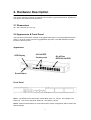
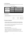
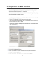
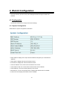
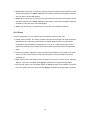
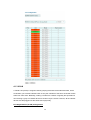
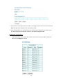
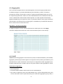
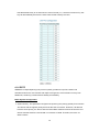
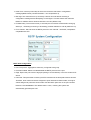
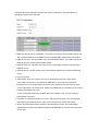
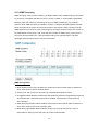
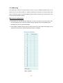
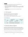
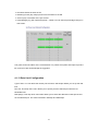
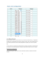
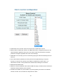
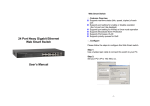
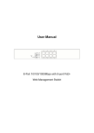
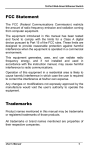
24-PORT POE+ WEB-MANAGED GIGABIT ETHERNET SWITCH WITH 4 SFP COMBO PORTS USER MANUAL Model 560900 INT-560900-01-UM-1013 FCC Warning This equipment has been tested and found to comply with the limits for a Class A digital device, pursuant to Part 15 of the FCC rules. These limits are designed to provide reasonable protection against harmful interference in a residential installation. This equipment generates, uses and can radiate radio frequency energy. It may cause harmful interference to radio communications if the equipment is not installed and used in accordance with the instructions. However, there is no guarantee that interference will not occur in a particular installation. If this equipment does cause harmful interference to radio or television reception, which can be determined by turning the equipment off and on, the user is encouraged to try to correct the interference by one or more of the following measures: Reorient or relocate the receiving antenna. Increase the separation between the equipment and receiver. Connect the equipment to an outlet on a circuit different from that to which the receiver is connected. Consult the dealer or an experienced radio/TV technician for help. CE Warning This is a Class A product. In a domestic environment, this product may cause radio interference, in which case the user may be required to take adequate measures. Contents Contents ............................................................................................................................ 3 1. Introduction ............................................................................................................... 5 1.1 Product Overview............................................................................................5 1.2 General Features ............................................................................................5 1.3 Software Features...........................................................................................5 1.4 Package Contents...........................................................................................6 2. Hardware Description................................................................................................. 7 2.1 Dimensions .....................................................................................................7 2.2 Appearance & Front Panel..............................................................................7 2.3 LED Indicators ................................................................................................8 2.4 Rear Panel ......................................................................................................8 2.5 Hardware Installation ......................................................................................8 3. Preparation for Web Interface...................................................................................10 4. Web UI Configuration ................................................................................................12 4.1 Configuration .......................................................................................................... 12 4.1.1 System Configuration.................................................................................12 4.1.2 Ports...........................................................................................................14 4.1.3 VLAN..........................................................................................................15 4.1.4 Aggregation................................................................................................17 4.1.5 LACP..........................................................................................................17 4.1.6 RSTP .........................................................................................................18 4.1.7 802.1X Configuration .................................................................................20 4.1.8 IGMP Snooping..........................................................................................22 4.1.9 Mirroring .....................................................................................................23 3 4.1.10 QoS ..........................................................................................................24 4.1.11 Filter Configuration...................................................................................26 4.1.12 PoE (Power over Ethernet) Configuration................................................26 4.1.13 Rate Limit Configuration ..........................................................................27 4.1.14 Storm Control ...........................................................................................28 4.2 Monitoring ............................................................................................................... 30 4.2.1 Statistic Overview ......................................................................................30 4.2.2 Detailed Statics ..........................................................................................30 4.2.3 LACP Status ..............................................................................................31 4.2.4 RSTP Status ..............................................................................................31 4.2.4 IGMP Status...............................................................................................32 4.2.5 VeriPHY .....................................................................................................33 4.2.6 Ping ............................................................................................................34 4.3 Maintenance ........................................................................................................... 35 4.3.1 Warm Restart .............................................................................................35 4.3.2 Factory Default...........................................................................................35 4.3.3 Software upload .........................................................................................35 4.3.4 Configuration File Transfer ........................................................................36 4.3.5 Logout .................................................................................................................. 36 5. Specifications ............................................................................................................38 4 1. Introduction 1.1 Product Overview This switch is a 24-port 10/100/1000M PoE+ (with four Combo SFP ports) Rackmount WebSmart Switch. It supports the IEEE 802.3at Power over Ethernet standard, with a maximum of 390 watts power consumption per system. The switch also provides exceptionally smart web management features, such as VLAN, QoS, RSTP, IGMP Snooping, LACP, IEEE 802.1X and Storm Control. The switch is a standard 19” rackmount design to fit into the rack environment. With these features, the switch is a superb choice for a medium or large network environment to strengthen its network connection and efficiency. 1.2 General Features 24-Port 10/100/1000BaseT(X) PoE+ with 4 Combo SFP open slots IEEE 802.3at, up to 30 W per port Maximum 390 W power consumption 48 Gbps non-blocking switching performance 8K MAC address table; up to 9K jumbo frames Web-based configuration and management 802.1Q VLAN, QoS, Link Aggregation, RSTP, IGMP Snooping and IEEE 802.1X 1.3 Software Features VLAN: 16, VLAN ID: 1 – 4094 Rapid Spanning Tree Protocol IGMP Snooping V1&V2 LACP/Trunk: up to 8 groups Quality of Service: up to 4 queues, 802.1p PoE Control: PoE Port Enabled/Disable, Status IEEE 802.1X, Source IP Filter Storm Control: Broadcast, Multicast, Flood Unicast Port: Port State, Speed/Duplex, Flow Control Rate Limiting, Port Mirroring Management: Web GUI, SNMP, password protection, configuration upload/download, firmware upgrades 5 1.4 Package Contents Before you start to install this switch, verify your package contains the following items: Switch Power cord User manual on CD Rackmount kit with 8 screws 6 2. Hardware Description This section primarily presents the hardware of the switch, physical dimensions, appearance, front panel, rear panel and LED indicators. 2.1 Dimensions 45 × 440 × 330 mm (H × W × D) 2.2 Appearance & Front Panel The front panel of the switch consists of 24 gigabit RJ45 ports. Four of the gigabit RJ45 ports (Ports 1–4) are in combo with the four gigabit SFP open slots. The LED Indicators are also located on the front panel. Appearance LED Display 4 RJ-45/SFP Combo ports RJ-45 Port IEEE 802.3at PSE Reset Button Front Panel Note 1: The SFP ports are shared with normal RJ45 ports 1, 2, 3 and 4. For example: The RJ45 Port 1 can not be used when SFP Port 1 is linked to a device. Note 2: Press the Reset button for 5 seconds and the system configuration will be reset to the default settings. 7 2.3 LED Indicators The LED Indicators present real-time information of systematic operation status. This table provides description of LED status and the meaning. Table 1-1 LED Indicators LED Status Description On Power Link / ACT PoE Power on Switched to Off or disconnected from power source Link Data activating No device is attached Port is linked to powered device No powered device is connected Off On Flashing Off On Off 2.4 Rear Panel The 3-pronged power plug is on the rear panel of the switch as shown as below. This is reserved for AC power input. 2.5 Hardware Installation The switch is typically mounted in a 19” rack, installed in an IT room or other secured place. Make sure all the power cables, Ethernet cables, mounting screws and such are prepared and installed as described below, including clearance for adequate ventilation. Ports 1–24 are copper ports, requiring UTP/STP cable. These ports are also PoE ports, requiring CAT 5/5e or above for the PoE application. Ports 1–4 are also the combo SFP ports. Ethernet cable requirements The wiring cable types for data transmission are as below. 10 Base-T: 2-pair UTP/STP Cat. 3, 4, 5 cable, EIA/TIA-568 100-ohm (max. 100m) 100 Base-TX: 2-pair UTP/STP Cat. 5 cable, EIA/TIA-568 100-ohm (max. 100m) 1000 Base-T: 4-pair UTP/STP Cat. 5 cable, EIA/TIA-568 100-ohm (max. 100m) The wiring cable types for data transmission and power delivery in any speed should be Cat5 or above. 8 SFP Installation When using the SFP ports, make sure the SFP types are compatible in terms of transmission distance, wavelength and fiber cable can meet your request. When connecting an SFP transceiver, plug in the SFP fiber transceiver first. The SFP transceiver has two plugs for fiber cable: one is TX (transmit); the other is RX (receive). Cross-connect the transmit channel at each end to the receive channel at the opposite end. Rackmount Installation Attach the brackets to the device using the screws provided in the rackmount kit. Mount the device in a 19” rack using four rackmounting screws provided by the rack manufacturer. 9 3. Preparation for Web Interface The Web management page allows you to use a standard Web browser — such as Microsoft Internet Explorer, Google Chrome or Mozila Firefox — to configure and interrogate the switch from anywhere on the network. Before you attempt to use the Web user interface to manage switch operation, verify that your switch is properly installed on your network and that every PC on this network can access the switch via the Web browser. 1. Verify that your network interface card (NIC) is operational, and that your operating system supports the TCP/IP protocol. 2. Power on the switch and connect your computer to the switch. 3. The switch default IP address is 192.168.2.1. The switch and the connected PC(s) should locate within the same IP subnet. 4. Change your computer's IP address to 192.168.2.XX or another IP address that is located in the 192.168.2.x subnet. (For example: IP address = 192.168.2.30; subnet mask = 255.255.255.0) Launch the Web browser and log in. 5. Launch the Web browser on the PC. 6. Enter “http://192.168.2.1” (or the IP address of the switch), then press <Enter>. 7. The login screen will appear next. 8. Key in the password. Default password is no password. Click Apply. 10 Login Screen The factory default password is no password: Just click Apply to log in directly. Once the login is complete, the interface displays “Password successfully entered.” Note: To help ensure your switch’s security, go to the System Configuration page and set up a new password. Below is the main screen. The left side shows the function list and the right side shows the configuration parameters. Troubleshooting If you can't log in to the switch, the following steps can help you to identify the problem. 1. Switch to DOS command mode and enter "ipconfig" to check the NIC setting. Enter "ping 192.168.2.1" to verify a normal response time. 2. Check the security and firewall settings of your computer. 3. Try a different Web browser. 11 4. Web UI Configuration This part instructs you how to set up and manage the switch through the Web user interface. 4.1 Configuration This section shows how to configure the switch settings. 4.1.1 System Configuration What follows is system configuration information. MAC Address: Displays the unique hardware address assigned by the manufacturer (default). S/W Version: Displays the switch’s firmware version. H/W Version: Displays the switch’s hardware version. Active IP Address: The current active IP address of the switch. Active Subnet mask: The current active subnet mask of the IP address. Active Gateway: The current active gateway of the switch. DHCP Server: The IP of the DHCP server. Displays after DHCP Client is enabled. Lease Time Left: Display after DHCP Client is enabled. 12 DHCP Enabled: Click the box to enable DHCP Client mode. Fallback IP address: Manually assign the IP address that the network is using. The default IP is 192.168.2.1. Fallback Subnet Mask: Assign the subnet mask to the IP address. Fallback Gateway: Assign the network gateway for an industrial switch. The default gateway is 192.168.2.254. Management VLAN: ID of a configured VLAN (1-4094) through which you can manage the switch. By default, all ports on the switch are members of VLAN 1. However, if the management VLAN is changed, the management station must be attached to a port belonging to this VLAN. Name: Enter the new user name information. Password: Enter the new password (the default value is no password). SNMP Enabled: Enables or disables SNMP on the switch. Supports SNMP version 1 and 2c management clients. SNMP Trap Destination: IP address of the trap manager to receive notification messages from this switch. Traps indicating status changes are issued by the switch to specified trap managers. You must specify trap managers so that key events are reported by this switch to your management station. 13 SNMP Read Community: A community string that acts like a password and permits access with Read privilege to the SNMP database on this switch. Authorized management stations are only able to retrieve MIB objects. SNMP Write Community: A community string that acts like a password and permits access with Write privilege to the SNMP database on this switch. Authorized management stations are able to modify the value of the MIB objects. SNMP Trap Community: A community string sent with the notification operation. 4.1.2 Ports In Port Configuration, you can set and view the operation mode for each port. Enable Jumbo Frames: This switch provides more efficient throughput for large sequential data transfers by supporting jumbo frames on Gigabit Ethernet ports up to 9216 bytes. Compared to standard Ethernet frames that run only up to 1.5 KB, using jumbo frames significantly reduces the per-packet overhead required to process protocol encapsulation fields. Power Saving Mode: Adjusts the power provided to ports based on the length of the cable used to connect to other devices. Only sufficient power is used to maintain connection requirements. Mode: Allows user to manually set the port speed, such as Auto, 10 half, 10 Full, 100 Half, 100 Full, 1000 Full or Disabled. Click Apply to complete the configuration procedure. Flow Control: Allows you to manually enable or disable the Flow Control feature. Check the box of the specific ports you want, the click Apply to complete the configuration procedure. 14 4.1.3 VLAN A Virtual LAN (VLAN) is a logical network grouping that limits the broadcast domain, which would allow you to isolate network traffic so only the members of the same VLAN will receive traffic from each other. Basically, creating a VLAN from a switch is logically the equivalent of reconnecting a group of network devices to another Layer 2 switch. However, all the network devices are still plugged into the same switch physically. Port Segmentation (VLAN) Configuration 15 VLAN ID: ID of a configured VLAN (1-4094, no leading zeroes). Enter the new ID and click Add. The Web UI is directed to the VLAN Setup screen. VLAN Configuration List: Lists all the current VLAN groups created for this system (up to 16). VLAN groups can be defined. VLAN 1 is the default untagged VLAN. VLAN Setup Configuration This screen allows you to select the member ports of the VLAN you added. Select the ports and click Apply to activate. 16 4.1.4 Aggregation Port trunk allows multiple links to be bundled together and act as a single physical link for increased throughput. It provides load balancing and redundancy of links in a switched internetwork. Actually, the link does not have an inherent total bandwidth equal to the sum of its component physical links. Traffic in a trunk is distributed across an individual link within the trunk in a deterministic method called a hash algorithm. The hash algorithm automatically applies load balancing to the ports in the trunk. A port failure within the trunk group causes the network traffic to be directed to the remaining ports. Load balancing is maintained whenever a link in a trunk is lost or returned to service. Aggregation / Trunking Configuration To assign the ports to a trunk, click the required trunk number ports, then click Apply. The below example shows that Ports 3 and 4 are the member ports of Trunk Group 1. 4.1.5 LACP IEEE 802.3ad Link Aggregation Control Protocol (LACP) increases bandwidth by automatically aggregating several physical links together as a logical trunk and providing load balancing and fault tolerance for uplink connections. Once the port is configured as a Static Aggregation port, the area will become gray. It means a port can only be a member of the Aggregation or LACP. LACP Port Configuration Port: The port ID. Protocol Enabled: Enables LACP Protocol on the associated port. Key Value: Configures a port's LACP administration key. The port administrative key must be set to the same value for ports that belong to the same link aggregation group (LAG). If 17 this administrative key is not set when an LAG is formed (i.e., it has the null value of 0), this key will automatically be set to the same value as that used by the LAG. 4.1.6 RSTP IEEE 802.1w Rapid Spanning tree protocol (LACP) provides a loop-free network and redundant links to the core network with rapid convergence to ensure faster recovery from failed links, enhancing overall network stability and reliability. RSTP System Configuration System Priority: This parameter configures the spanning tree priority globally for this switch. The device with the highest priority becomes the STP root device. However, if all devices have the same priority, the device with the lowest MAC address will then become the root device. Number between 0 and 61440 in increments of 4096. Therefore, there are 16 distinct values. 18 Hello Time: Interval (in seconds) at which the root device transmits a configuration message (BPDU frame). Number between 1 and 10 (default is 2). Max Age: The maximum time (in seconds) a device can wait without receiving a configuration message before attempting to reconfigure. This also means the maximum lifetime for a BPDU frame. Number between 6 and 40 (default is 20). Forward Delay: The maximum time (in seconds) the root device will wait before changing states (i.e., discarding to learning to forwarding). Number between 4 and 30 (default is 15). Force Version: Set and show the RSTP protocol to use. Normal - use RSTP; Compatible compatible with STP. RSTP Port Configuration Port: The port ID. Aggregations mean any configured trunk group. Protocol Enabled: Select to enable/disable the RSTP protocol for the port. Edge: Expect the port to be an edge port (linking to an end station) or a link to another STP device. Path Cost: This parameter is used by the STP to determine the best path between devices. Therefore, lower values should be assigned to ports attached to faster media, and higher values assigned to ports with slower media. Set the RSTP path cost on the port. Number between 0 and 200000000. The default value is “auto,” meaning the system will automatically generate path cost. 19 4.1.7 802.1X Configuration IEEE802.1X provides a security standard for network access control, especially in Wi-Fi wireless networks. 802.1X holds a network port disconnected until authentication is completed. The switch uses Extensible Authentication Protocol over LANS to exchange authentication protocol client identity with the client, and forward it to another remote RADIUS authentication server to verify access rights. The EAP packet from the RADIUS server also contains the authentication method to be used. The client can reject the authentication method and request another, depending on the configuration of the client software and the RADIUS server. Depending on the authenticated results, the port is either made available to the user or the user is denied access to the network. 20 The RADIUS servers make the network a lot easier to manage for the administrator by gathering and storing the user lists. Mode: By default, 802.1x is disabled. To use EAP for security, select enabled and set the 802.1X Global Settings for the Radius Server and applicable authentication information. RADIUS server IP: The IP Address of the external Radius Server, you need to specify an RADIUS server to enable 802.1X authentication. RADIUS UDP Port: The UDP port used for the communication between the switch and RADIUS server. RADIUS Secret: The Key used for the communication between the switch and RADIUS server. Port: The port ID. Admin State: There are 3 types: Auto, Force Authorized and Force Unauthorized. - Auto: Select Auto when you enabled the IEEE 802.1X. If the client is successfully authorized, the port is authorized to be used as well. Otherwise, the port can’t be used. - Force Authorized: The default value. Whether the IEEE 802.1X is enabled or not, the port is always authorized to be used. - Force Unauthorized: Whether the IEEE 802.1X is enabled or not, the port is always unauthorized to be used. Port State: It indicates the status of the port. Authorized means the port is successfully authorized by the RADIUS server or the port is configured as “Force Authorized.” Others: Re-authenticate allows restart the authentication process, Force Reinitialize reinitializes the process and Statistics displays the IEEE 802.1X counters and information of each port. 21 4.1.8 IGMP Snooping IGMP Snooping is the process of listening to IGMP network traffic. IGMP Snooping, as implied by the name, is a feature that allows a Layer 2 switch to “listen in” on the IGMP conversation between hosts and routers by processing the Layer 3 IGMP packets sent in a multicast network. When IGMP Snooping is enabled in a switch, it analyzes all IGMP packets between hosts connected to the switch and multicast routers in the network. When a switch hears an IGMP report from a host for a given multicast group, the switch adds the host’s port number to the multicast list for that group. And, when the switch hears an IGMP Leave, it removes the host’s port from the table entry. It also prevents flooding of IP multicast traffic, and limits bandwidth-intensive video traffic to only the subscribers. IGMP Configuration IGMP Enabled: When this is enabled, the switch will monitor network traffic to determine which hosts want to receive multicast traffic. Router Ports: Set if ports are connecting to the IGMP administrative routers. Unregistered IPMC Flooding enabled: Set the forwarding mode for unregistered (not-joined) IP multicast traffic. The traffic will flood when enabled, and forward to router ports only when disabled. IGMP Snooping Enabled: When enabled, the port will monitor network traffic to determine which hosts want to receive the multicast traffic. IGMP Querying Enabled: When enabled, the port can serve as the Querier, which is responsible for asking hosts if they want to receive multicast traffic. 22 4.1.9 Mirroring Port Mirroring is used on a network switch to send a copy of network packets seen on one switch port (or an entire VLAN) to a network monitoring connection on another switch port. This is commonly used for network appliances that require monitoring of network traffic, such as an intrusion-detection system. Mirroring Configuration Port to Mirror to: The port that will “duplicate” or “mirror” the traffic on the source port. Only incoming packets can be mirrored. Packets will be dropped when the available egress bandwidth is less than ingress bandwidth. Ports to Mirror: Select the ports that you want to mirror from this section of the page. A port will be mirrored when the “Mirroring Enabled” option is selected. 23 4.1.10 QoS In QoS Mode, select QoS Disabled, 802.1p or DSCP to configure the related parameters. QoS Mode: QoS Disabled When the QoS Mode is set to QoS Disabled, the QoS is disabled. QoS Mode: 802.1p Packets are prioritized using the 802.1p field in the VLAN tag. This field is three bits long, representing the values 0 - 7. When the QoS Mode is set to 802.1p, the 802.1p Configuration table appears, allowing you to map each of the eight 802.1p values to a local priority queue (low, normal, medium or high). The default settings are shown below. When the QoS Mode is set to 802.1p, the 802.1p Configuration table is displayed as shown below. The Custom Prioritize Traffic is the default and suggested value. 24 QoS Mode: DSCP DSCP: Packets are prioritized using the DSCP (Differentiated Services Code Point) value. The DSCP is a six-bit field that is contained within an IP (TCP or UDP) header. The six bits allow the DSCP field to take any value in the range 0 - 63. When QoS Mode is set to DSCP, the DSCP Configuration table is displayed, allowing you to map each of the DSCP values to a hardware output queue (low, normal, medium or high). The default settings map all DSCP values to the high-priority egress queue. User can use the Prioritize Traffic drop-down list to quickly set the values in the DSCP Configuration table to a common priority queue. Use Custom if you want to set each value individually. When the QoS Mode is set to DSCP, the DSCP Configuration table is displayed as shown below. Enter the DSCP Value and Priority mapping in the fields on the bottom half. 25 Queue Mode: Strict: Services the egress queues in sequential order, transmitting all traffic in the higher-priority queues before servicing lower-priority queues. WRR: Weighted Round-Robin shares bandwidth at the egress ports by using scheduling weights with default values of 1, 2, 4, 8 for queues 0 through 7, respectively. (This is the default selection.) * Note: WRR can only be selected if Jumbo Frame mode is disabled on the Port Configuration screen. 4.1.11 Filter Configuration There are three modes that you can choose for filter configuration: Disabled: When this mode is disabled, there is no protection here. Static: The IP address you entered here can’t access the switch. DHCP: The IP address retrieved from the DHCP server can’t access the switch. 4.1.12 PoE (Power over Ethernet) Configuration PoE technology is a system to pass electrical power safely, along with data, on Ethernet cabling. Power is supplied in common mode over two or more of the differential pairs of wires found in the Ethernet cables and comes from a power supply within a PoE-enabled networking device (such as a switch) or can be injected into a cable run with a midspan power supply. This screen shows the PoE status when connected or disconnected to the PD device. PoE Enabled: POE of the port is able to supply power to the attached PD (powered device). 26 PD Class: Detect the class of PD. Delivering Power (W): Output power from the switch to the PD. Current (mA): The status of the port current. Power Budget [%] ( Per 8 port total power = 130W): You can see the percentage change on this screen. The green shows the status of the connected PD. To protect the system and improve product life, lower than 80% Power Budget is suggested. 4.1.13 Rate Limit Configuration Type of Port: You can define the certain port as Policer and Shaper before you set up the rate limit. No Limit: This drop-down menu allows you to specify that the selected port will have no bandwidth limit. Rate (kbps): This drop-down menu also allows you to select the data rate in kbits per second for the selected port. The value is between 128 kbps and 3968 kbps. 27 4.1.14 Storm Control Broadcast storms may occur when a device on your network is malfunctioning, or if application programs are not well designed or properly configured. If there is too much broadcast traffic on your network, performance can be severely degraded or everything can come to complete halt. You can protect your network from broadcast storms by setting a threshold for broadcast traffic for each port. Any broadcast packets exceeding the specified threshold will then be dropped. Storm Control Configuration There are three types of traffic which can be rate limited: broadcast, multicast and flooded Unicast. 28 Enable Rate Limit: Click the check box and the rate to enable storm control. Rate (number of frames per second): The Rate field is set by a single drop-down list. The same threshold is applied to every port on the switch. When the threshold is exceeded, packets are dropped, regardless of the flow-control settings. ICMP Rate: This can keep you from continuously pinging the switch and wasting the CPU resource. Learn Frame Rate: By default, the switch performs wire-speed learning on all ports. However, if some kind of unknown source MAC is classified as a “learn frame,” it is redirected to the CPU. These packets will be filtered after enabling this command. Broadcast: Broadcast traffic. Multicast: Unknown Multicast Traffic. Before IGMP Snooping is enabled, all the multicast is flooded and will be filtered by this command. Flooded Unicast Rate: Any source MAC not yet recognized by the switch is considered unknown unicast. This command can help limit such traffic. 29 4.2 Monitoring 4.2.1 Statistics Overview Statistic Overview for all ports You can mirror traffic from any source port to a target port for real-time analysis. The following figures show the Statistics Overview. 4.2.2 Detailed Statistics To view the statistics of individual ports, click one of the linked port numbers for details. Clear: To renew the details collected and displayed. Refresh: To reset the details displayed. 30 4.2.3 LACP Status LACP Aggregation Overview LACP allows for the automatic detection of links in a Port Trunking Group. Port: The port number. Port Active: Shows if the port is a member of an active LACP group. Partner Port Number: A list of the ports attached at the remote end of this LAG link member. Operational Port Key: Current operational value of the key used by this LAG. LACP Port Status Active LACP ports are capable of processing and sending LACP control frames. This allows LACP-compliant devices to negotiate the aggregated link so the group may be changed dynamically as needs require. 4.2.4 RSTP Status RSTP VLAN Bridge Overview 31 Hello Time: Interval (in seconds) at which the root device transmits a configuration message. Max Age: The maximum time (in seconds) a device can wait without receiving a configuration message before attempting to reconfigure. All device ports (except for designated ports) should receive configuration messages at regular intervals. Any port that ages out STA information (provided in the last configuration message) becomes the designated port for the attached LAN. If it is a root port, a new root port is selected from among the device ports attached to the network. Fwd Delay: The maximum time (in seconds) the root device will wait before changing states (i.e., discarding to learning to forwarding). This delay is required because every device must receive information about topology changes before it starts to forward frames. In addition, each port needs time to listen for conflicting information that would make it return to a discarding state; otherwise, temporary data loops might result. Topology: Indicates if Spanning Tree topology is steady or undergoing reconfiguration. (The time required for reconfiguration is extremely short, so no values other that “steady” state are likely to be seen in this field.) Root ID: The priority and MAC address of the device in the Spanning Tree that this switch has accepted as the root device, and the port connected to the root device. RSTP Port Status Port/Group: The number of a port or the ID of a static trunk. Path Cost: The cost for a packet to travel from this port to the root in the current Spanning Tree configuration. The slower the media, the higher the cost. Edge Port: Shows if this port is functioning as an edge port, either through manual selection (see the RSTP Port Configuration table) or auto-detection. Note that if the switch detects another bridge connected to this port, the manual setting for Edge Port will be overridden, and the port will instead function as a point-to-point connection. P2P Port: Shows if this port is functioning as a Point-to-Point connection to exactly one other bridge. The switch can automatically determine if the interface is attached to a point-to-point link or to shared media. If shared media is detected, the switch will assume that it is connected to two or more bridges. Protocol: Shows the Spanning Tree protocol functioning on this port, either RSTP or STP (that is, STP-compatible mode). 4.2.4 IGMP Status IGMP Status IGMP Status shows the IGMP Snooping statistics for the whole switch. 32 VLAN ID: VLAN ID number. Querier: Shows whether Querying is enabled. Queries transmitted: Shows the number of transmitted Query packets. Queries received: Shows the number of received Query packets. v1 Reports: Shows the number of received v1 Report packets. v2 Reports: Shows the number of received v2 Report packets. v3 Reports: Shows the number of received v2 Report packets. v3 Leave: Shows the number of v3 leave packets received. 4.2.5 VeriPHY VeriPHY Cable Diagnostics You can perform cable diagnostics for all ports or selected ports to diagnose any cable faults (short, open etc.) and feedback a distance to the fault. Cable Diagnostics: Cable diagnostics is performed on a per-port basis. Select the port number from the drop-down list. Click Apply to start the test. Cable Status: Shows the cable length and operating conditions and isolates a variety of common faults that can occur on Cat5 twisted pair cabling. 33 4.2.6 Ping This command sends ICMP echo request packets to another node on the network. Ping Parameters Target IP Address: IP address of the host. Count: Number of packets to send. (Range: 1-20) Time Out: Sets the time period the host will be pinged. Use the ping command to see if another site on the network can be reached. The following are some results of the ping command: Normal response: The normal response occurs in 1 to 10 seconds, depending on network traffic. Destination does not respond: If the host does not respond, a “timeout” appears in 10 seconds. Destination unreachable: The gateway for this destination indicates that the destination is unreachable. Network or host unreachable: The gateway found no corresponding entry in the route table. Press <Esc> to stop pinging. 34 4.3 Maintenance 4.3.1 Warm Restart Click Yes to restart the switch. The reset will be complete when the power lights stop blinking. 4.3.2 Factory Default Forces the switch to restore the original factory settings. To reset the switch, select “Reset to Factory Defaults” from the drop-down list and click Apply. The LAN IP Address, Subnet Mask and Gateway IP Address will be reset to their factory settings. If you forget the password, you can press the Reset button on the front panel for 5 seconds. Then the system will be reset to the default configuration. 4.3.3 Software Upload Select “Upgrade Firmware” from the Tools drop-down list then click on Browse to select the firmware file. Click Apply to upgrade the selected switch firmware file. Figure: Browse and Upload new software. 35 The “Software successfully loaded” message allows you to activate the new software. After you click Yes, the following message displays. 4.3.4 Configuration File Transfer Configuration File Transfer allows you to save the switch’s current configuration or restore a previously saved configuration back to the device. Configuration files can be saved to any location on the Web management station. Click Browse to choose a file location on the Web management station or to find a saved configuration file. Click Upload to save a configuration or Download to restore a configuration. 4.3.5 Logout The administrator has write access for all parameters governing the onboard agent. You should therefore assign a new administrator password as soon as possible, and store it in a safe place. 36 37 Revision History Edition Date Modifications V1.1 Jan. 31, 2013 Update the product information. Revise the Web GUI description of the features. Add revision history 5. Specifications Standards • IEEE 802.1d (Spanning Tree Protocol) • IEEE 802.1p (Traffic Prioritization) • IEEE 802.1q (VLAN Tagging) • IEEE 802.1w (Rapid Spanning Tree Protocol) • IEEE 802.3ad (Link Aggregation) • IEEE 802.3 (10Base-‐T Ethernet) • IEEE 802.3ab (Twisted Pair Gigabit Ethernet) • IEEE 802.3ad (Link Aggregation Control Protocol LACP) • IEEE 802.3af (Power over Ethernet 802.3at Type 1) • IEEE 802.3at (Power over Ethernet 802.3at Type 2) • IEEE 802.3u (100Base-‐TX Fast Ethernet) • IEEE 802.3x (flow control, for full duplex mode) General • Media support: -‐ 10Base-‐T Cat3, 4, 5 UTP/STP RJ45 -‐ 100Base-‐TX Cat5 UTP/STP RJ45 -‐ 1000Base-‐T Cat5e UTP/STP RJ45 • Packet filter/forwarding rate: -‐ 1,488,000 pps (1000 Mbps) -‐ 148,800 pps (100 Mbps) -‐ 14,880 pps (10 Mbps) • MAC address table: 8k • Backplane speed / switch fabric: 48 Gbps 38 • Switch architecture: store and forward • Configuration Options: -‐ Port link speed: 10 Mbps, 100 Mbps, 1000 Mbps or auto-‐negotiation -‐ PoE on/off per port -‐ Flow control on/off per port -‐ VLAN -‐ Rate limiting (ingress rate and egress rate) -‐ Port Mirroring -‐ Port Aggregation/LACP: 8 groups -‐ Broadcast Storm configuration with broadcast rate, multicast rate, and flooded unicast rate -‐ IGMP Snooping -‐ Quality of Service (QoS): port-‐based or DSCP -‐ Integrated VeriPHY cable diagnostics tool -‐ Integrated ICMP Ping client sends ping requests to other network nodes -‐ SNMPv1/v2c (Simple Network Management Protocol) -‐ LAN settings (IP address, Gateway, etc.) • Certifications: FCC Class A, CE LEDs • PoE • Power • Link/activity Power • Input: 90 – 240 V AC, 50 – 60 Hz • Power consumption: 390 watts (maximum) Environmental • Metal housing • Dimensions: 440 (W) x 331 (L) x 44 (H) mm (17.3 x 13.0 x 1.7 in.) • Weight: 4.7 kg (10.36 lbs.) • Operating temperature: 0 – 40°C (32 – 104°F) • Operating humidity: 10 – 90% RH, non-‐condensing • Storage temperature: -‐20 – 90°C (-‐4 – 194°F) Note: Specifications are subject to change. 39