1
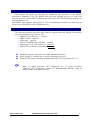
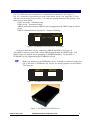
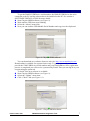
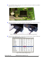
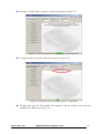
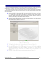
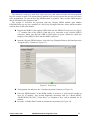
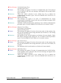
DMAX Rev. 3 DMAX Automotive Diagnostic Tool User’s Guide TABLE OF CONTENTS 1. PREFACE .......................................................................................................................................3 2. CHECKLIST AND REQUIREMENTS .........................................................................................3 3. DEVICE DESCRIPTION ...............................................................................................................4 4. SOFTWARE INSTALLATION .....................................................................................................5 5. THE USB DEVICE SERIAL NUMBER and SOFTWARE UPDATE .........................................7 6. IN-CIRCUIT SKIM READING BY THE CLIP ............................................................................8 7. SKIM NUMBER READING VIA OBDII-J1850 BUS................................................................12 8. THE SKIM NUMBER READING VIA THE OBDII-CAN BUS ...............................................16 9. THE VIN NUMBER EDIT VIA THE OBDII .............................................................................17 10. KEY PROGRAMMING VIA THE OBDII ................................................................................20 11. KEY ERASING VIA THE OBDII .............................................................................................22 12. READ/CLEAR DIAGNOSTIC TROUBLE CODES (DTC) .....................................................24 12. ERRORS AND TROUBLESHOOTING ...................................................................................26 13. THE SKIM POPPER TOOL ......................................................................................................28 ©DMAX 2008, 2009 DMAX Automotive Diagnostic Tool 2 1. PREFACE This manual will guide you through the installation and operation of the DMAX Automotive Diagnostic Tool. The DMAX-Tool has been designed not only to work with Chrysler vehicles via the OBD II connector but also to direct the EEPROM programming via the programming clip. The DMAX-Tool supports either J1850 or CAN communication interfaces the same way as 24Cxx series EEPROM or 95xxx EEPROM series. 2. CHECKLIST AND REQUIREMENTS The following checklist describes what items are supplied with the DMAX-Tool and the system requirements if it is used by a PC. DMAX-Tool USB device – supplied OBD II Cable – supplied USB cable – supplied SOIC-8 EEPROM Clip with cable – supplied Skim Popper Tool (See section 13) – Optional DMAX-Tool software on CD-ROM – Optional Desktop/Laptop PC and with a free USB Communication Port Power supply 12 Volt/500 mA is used for working out of a car. Windows (XP/Vista) with the preinstalled Microsoft .NET Framework Ver. 3.5 ©DMAX 2008, 2009 Note: To install Microsoft .NET Framework Ver. 3.5 please download Microsoft .NET Framework Version 3.5 Redistributable Package (x86) at address: http://www.microsoft.com/ DMAX Automotive Diagnostic Tool 3 3. DEVICE DESCRIPTION The DMAX-Tool USB device includes four connectors and two LEDs (See Figure 3). 12V. PC USB connector is intended for communication with the PC (See Figure 1). Ext. 12 V connector is used when you work on the bench, out of a car. Apply the 12 Volt/ 500 mA external power source to Ext. 12 V connector paying attention to the polarity. Also, there are two status LEDs: USB is not ready – blinking orange. USB is ready – permanent orange. OBD II status shows that the OBD II cable is plugged into the OBD II plug in vehiclegreen. OBD II communication is in progress - orange or blinking. PC USB Ext. 12V USB status OBDII status DMX Figure1. The DMAX-Tool USB device front panel At the rear panel there are two connectors, OBD II and PROG (See Figure 2). The OBD II connector goes to the vehicle OBD II plug through the OBD II cable. The PROG connector supports the programming of EEPROM memory. Use the SOIC-8 EEPROM Clip for programming the EEPROM in-circuit. Note: Pay attention to the EEPROM 1-st pin. It should be connected to the first pin of the SOIC-8 EEPROM Clip. Please see detailed pictures in the DMAXTool software. OBD II PROG Figure 2. The DMAX-Tool USB device rear panel. Figure 3. The DMAX-Tool USB device. ©DMAX 2008, 2009 DMAX Automotive Diagnostic Tool 4 4. SOFTWARE INSTALLATION To operate with the DMAX-Tool a user has to install the control software on the Personal Computer. The DMAX-Tool software requires not only the preinstalled .NET Framework Ver. 3.5 package but also the installed USB device driver. Please follow next steps to complete the installation. Check if the.NET Framework Ver. 3.5 package is installed on your PC. If you use the Win. XP, you should go to Start>Setting>Control Panel>Add Remove Programs (See Figure 3) Figure 3. Microsoft .NET Framework 3.5 If there is no Microsoft .NET Framework 3.5, please download the Microsoft .NET Framework Version 3.5 Redistributable Package (x86) from this address: http://www.microsoft.com/ and install it. Execute Setup.exe to install the DMAX-Tool software. Follow the instructions to select installation options. After installation of this software, the USB driver Setup Wizard will start working (Se Figure 4.) Figure 3. USB Driver Setup Wizard ©DMAX 2008, 2009 DMAX Automotive Diagnostic Tool 5 If the Error message: “There is 1 currently connected device…” appears (See Figure 4) you should disconnect all USB devices from the PC and press the “Retry” button. Figure 4. USB Driver Setup Wizard Error After the message box: “Please Connect USB Device to PC” appears (See Figure 5), connect the DMAX-Tool USB device to the Personal Computer and make sure that it is powered up (USB status LED is lit). Press the “OK” button. Figure 5. USB Driver Setup Wizard message box If the USB Driver was installed successfully the USB Status LED should light up orange. To check the driver version and the operation status on the PC with Win XP operating system go to: Start>Setting>Control Panel>System>Hardware>Device Manager>Human Interface Device>DMAX USB Device (See Figure 6). Figure 6. DMAX USB device driver location Note: If the USB driver is not installed, reinstall it by using the USB Driver Setup Wizard. Figure 7. USB driver Setup Wizard ©DMAX 2008, 2009 DMAX Automotive Diagnostic Tool 6 5. THE USB DEVICE SERIAL NUMBER and SOFTWARE UPDATE To get the DMAX USB Device serial number, the DMAX USB Device has to be connected to the PC and the software has to be installed on the PC. See section 4. SOFTWARE INSTALLATION for more details. Start Chrysler SKIM software (see Figure 8). Wait until the USB icon stops blinking. Select the “About” menu item. Now you can read the USB Module Serial Number and copy it to the clip board. Figure 8. Chrysler SKIM software You can download new software form our web site: http://www.autoeltools.com/ Downloading is available for registered users only. To get the password you have to provide the valid USB Device serial number and your Email address. Once registration process is completed you will receive a password by Email. Then you can log-in to your account using the password. To check if the new software is available: Start Chrysler SKIM software (see Figure 8). Select the “Update” menu item. Click “Check” link (see Figure 8.1). Figure 8.1. Chrysler SKIM software ©DMAX 2008, 2009 DMAX Automotive Diagnostic Tool 7 6. IN-CIRCUIT SKIM READING BY THE CLIP In-Circuit reading interface is implemented to work with modules, which do not support a diagnostic way to work with the target module. Usually, this is the first generation of J1850 modules. This section describes step by step operation with the Chrysler SKIM module (part number 56042298AD) installed in a 2000 Jeep Grand Cherokee. Other similar modules could be done in the same manner. The new Skim Popper tool allows you to gain access and read the Skim Chip. Refer to the section 13, the Skim Popper tool. If you do not have this tool please do next steps very precise to prevent damaging of a SKIM module. Gently remove the SKIM module from a car paying special attention to RF coil (see Figure 9). Figure 9. SKIM module P56042298AD Remove the top plastic cover and unsolder two pins (see Figure 10). Figure 9. Unsoldering the pins ©DMAX 2008, 2009 DMAX Automotive Diagnostic Tool 8 Locate 24LC02 memory and remove the varnish from the pins by knife or by another appropriate tool (see Figure 10). Figure 10. Removing the varnish from the pins Apply the External 12 Volt to the D-MAX USB module then connect the SOIC-8 EEPROM Clip cable to the “PROG” connector (see Figure 11). Figure 11. Required connections for the In-circuit EEPROM programming Start the Chrysler SKIM software, select the Jeep Grand Cherokee Limited. (2000) and press the “Read SKIM” button (see Figure 12). Figure 12.The SKIM reading procedure ©DMAX 2008, 2009 DMAX Automotive Diagnostic Tool 9 After the message “Put Programmer clip on to Memory” appears (see Figure 13), put the SOIC-8 EEPROM Clip on to the memory, as it is shown in the picture. Pay extra attention to the 1st pin. Both first pins on the memory and on the clip should match (see Figure 14). Otherwise, there is a risk of damage to the memory and the D-MAX USB module. First pin is marked by red color on the SOIC-8 clip. Note: On the SOIC-8 clip the first pin is marked by red color. SOIC-8 clip supplied with the D-MAX USB module may look different from what shown on the picture. Note: On the EEPROM memory, the 1st pin is usually marked by the round groove. Figure 13. The Connection Help Screen Figure 14.The Connection Help Screen, detailed view ©DMAX 2008, 2009 DMAX Automotive Diagnostic Tool 10 Press the “Continue Operation” button. If there is a poor contact between the clip and the memory, the “Pin Tester Error” screen will appear (see Figure 15). Pins with a bad connection are marked by red color. A couple of reasons could lead to this problem. For example, the varnish cover was not removed completely from the pins or the SOIC-8 Clip was not mounted well on the memory. When the poor contact problem is resolved, the SKIM number would be read automatically (see Figure 16). Figure 15. Pin Tester Error Screen Figure 16. SKIM number screen ©DMAX 2008, 2009 DMAX Automotive Diagnostic Tool 11 7. SKIM NUMBER READING VIA OBDII-J1850 BUS The SKIM reading via the OBD II connector is implemented to work with second generation modules which support the diagnostic way to work with the target module. As the J1850 protocol is used, the communication speed with the target module may take couple minutes on each procedure. To work with the J1850 SKIM module the additional two keys are needed. The first key is the “VALET” Key and the second key is “EMPTY” Key. The “VALET” Key does not have the RF-ID chip inside; it is just a piece of metal. The “EMPTY” Key is the brand new key, which was never programmed to any vehicle. This section describes step by step operation with the Chrysler SKIM module (part number P56010209AD), installed in a 2004 Jeep Wrangler Rubicon. Other similar modules could be done in the same manner. Plug-In the ODB II Cable and the USB Cable in to the DMAX-Tool device (see Figure 17). Another side of the ODB II Cable has to be connected to the vehicles ODB II connector. Make sure that the ODB II LED lights up green. Otherwise, check the integrity of the OBD II Cable and the OBD II connector. Figure 17. Connection of DMAX-Tool to vehicle ©DMAX 2008, 2009 DMAX Automotive Diagnostic Tool 12 Start the Chrysler SKIM software, select Jeep Wrangler Rubicon 2004 and press the “Read SKIM” button (see Figure 18). Figure 18. The SKIM number reading via OBD II Turn Ignition On and press the “Continue Operation” button (see Figure 19). Figure 19. The SKIM number reading via OBD II ©DMAX 2008, 2009 DMAX Automotive Diagnostic Tool 13 Approximately in one minute the software shows the VIN number, the SKIM module part number and the firmware version of the SKIM module. If the progress bar stays in the “marquee” mode for more than one minute it means that there is no SKIM module on the J1850-bus detected. In this case, check if the ignition is on and the OBD II cable is connected to the vehicle. Figure 20. The SKIM number reading, step 1 Turn the ignition off. Insert the “VALET” Key and turn the ignition on. Approximately in one minute the next screen will appear: Figure 21. The SKIM number reading, step 2 ©DMAX 2008, 2009 DMAX Automotive Diagnostic Tool 14 Turn the ignition off. Insert the “EMPTY” Key then turn the ignition on. Approximately in one minute the next screen will appear: Figure 22. The SKIM number reading, step 3 Turn the ignition off. Turn the ignition on. In one minute next screen will appear: ©DMAX 2008, 2009 Figure 23. The SKIM number reading, step 4 Note: If you get an error message during the operation, try to redo everything from the beginning. DMAX Automotive Diagnostic Tool 15 8. THE SKIM NUMBER READING VIA THE OBDII-CAN BUS The SKIM reading via the OBD II connector is implemented to work with third generation modules, which support a diagnostic way to work with the target module via the CAN protocol. This section describes step by step operation with the Chrysler WCM module (part number 56040542AN), installed in a 2005 Dodge Durango. Other similar modules could be done in the same manner. Plug-In the ODB II Cable and the USB Cable in to the DMAX-Tool device (see Figure 17). Another side of the ODB II Cable has to be connected to the vehicles ODB II connector. Make sure that the ODB II LED lights up green. Otherwise, check the integrity of the OBD II Cable and the OBD II connector. Start the Chrysler SKIM software, select Dodge Durango 2005 Adv./SLT (2005) and press the “Read SKIM” button (see Figure 24). Figure 24. The SKIM number reading via OBD II-CAN Turn the ignition on and press the “Continue Operation” button. In couple seconds the next screen will appear: Figure 25. The SKIM number reading via OBD II, step 1 ©DMAX 2008, 2009 DMAX Automotive Diagnostic Tool 16 9. THE VIN NUMBER EDIT VIA THE OBDII The VIN number edit function is useful if you have replaced the SKIM module or the PCM module. After the new module has been installed, the VIN number in the SKIM module and the VIN number in the PCM module have to be matched. To edit the VIN number in the SKIM module the SKIM number is required. Thus, read the SKIM number first as described in Sections 6, 7. Also, the Country Code edit function is implemented. This section describes step by step the operation with the Chrysler SKIM module (part number 56042298AD), installed in a 2000 Jeep Grand Cherokee Lim. Other similar modules could be done in the same manner. Plug-In the ODB II Cable and the USB Cable into the DMAX-Tool device (see Figure 17). Another side of the ODB II Cable has to be connected to the vehicles ODB II connector. Make sure that the ODB II LED lights up green. Otherwise, check the integrity of the OBD II Cable and the OBD II connector. Start the Chrysler SKIM software, select Jeep Grand Cherokee Lim. 2000 and press the “SKIM/WCM/VIN Edit” button (see Figure 26). Figure 26. The SKIM/WCM/VIN edit via OBD II Turn Ignition On and press the “Continue Operation” button (see Figure 19). Enter the SKIM number. If the SKIM number is incorrect, it will lock the module at least for 30 minutes. Any secured diagnostic operations such as a “Read SKIM”, “SKIM/WCM/VIN Edit”, “Erase Keys” or “Program a Key” will be disabled for 30 minutes. Enter a new VIN number. It must be the same as a PCM module. If you want to bring the module to the unprogramed state leave the VIN field blank. The blank VIN number allows you using the Chrysler diagnostic tool to program the VIN number. Enter a new Country Code. ©DMAX 2008, 2009 DMAX Automotive Diagnostic Tool 17 Press the “Validate Data” button to continue operation (see Figure 27). Figure 27. The VIN number and the Country Code fields edit In couple minutes you will see the next screen (see Figure 28). Figure 28. SKIM/WCM/VIN Edit procedure is completed To make sure that the VIN number has changed, read the module info. Press the “Module info” Button (see Figure 29). ©DMAX 2008, 2009 DMAX Automotive Diagnostic Tool 18 Figure 29. Verifying the VIN Edit procedure ©DMAX 2008, 2009 DMAX Automotive Diagnostic Tool 19 10. KEY PROGRAMMING VIA THE OBDII The Key Programming function is to be used to program a new Key. To add a new key the SKIM number is required. Thus, read the SKIM number first as described in Sections 6, 7. This section describes step by step an operation with the Chrysler SKIM module (part number 56042298AD), installed in a 2000 Jeep Grand Cherokee Lim. Other similar modules could be done in the same manner. Plug-In the ODB II Cable and the USB Cable into the DMAX-Tool device. (see Figure 17). Another side of the ODB II Cable has to be connected to the vehicles ODB II connector. Make sure that the ODB II LED lights up green. Otherwise, check the integrity of the OBD II Cable and the OBD II connector. Start the Chrysler SKIM software, select the Jeep Grand Cherokee Lim. 2000 and press the “Program a Key” button (see Figure 30). Figure 30. Program a Key Turn Ignition On and press the “Continue Operation” button (see Figure 19). Enter the SKIM number. If the SKIM number is incorrect, it will lock the module at least for 30 minutes. Any secured diagnostic operations as a “Read SKIM”, “SKIM/WCM/VIN Edit”, “Erase Keys”, or “Program a Key” will be disabled for 30 minutes. Press the “Validate Data” button to continue an operation (see Figure 31). ©DMAX 2008, 2009 DMAX Automotive Diagnostic Tool 20 Figure 31. Enter the SKIM Number Shortly thereafter you will see the next screen (see Figure 32). Figure 32. Programming New Key is Successful ©DMAX 2008, 2009 DMAX Automotive Diagnostic Tool 21 11. KEY ERASING VIA THE OBDII This function is only to be used if the owner lost a key and wants to disable all current ignition keys for security reasons. This means that all ignition keys not only current but also new ones have to be programmed. To erase all keys the SKIM number is required. Thus, read the SKIM number first as described in the Sections 6 and 7. The section 11 describes the operation with the Chrysler SKIM module (part number P56010209AD) step by step, installed in a 2004 Jeep Wrangler Rubicon. Other similar modules could be done in the same manner. Plug-In the ODB II Cable and the USB Cable into the DMAX-Tool device (see Figure 17). Another side of the ODB II Cable has to be connected to the vehicles ODB II connector. Make sure that the ODB II LED lights up green. Otherwise, check the integrity of the OBD II Cable and the OBD II connector. Start the Chrysler SKIM software, select the Jeep Wrangler Rubicon 2004 and press the “Program a Key” button (see Figure 33). Figure 33. Erase Keys Turn Ignition On and press the “Continue Operation” button (see Figure 19). Enter the SKIM number. If the SKIM number is incorrect, it will lock the module at least for 30 minutes. Any secured diagnostic operations such as a “Read SKIM”, “SKIM/WCM/VIN Edit”, “Erase Keys” or “Program a Key” will be disabled for 30 minutes. Press the “Validate Data” button to continue the operation (see Figure 34). ©DMAX 2008, 2009 DMAX Automotive Diagnostic Tool 22 Figure 34. Enter the SKIM Number Shortly thereafter you will see the next screen (see Figure 35). Figure 35. Erase All Keys Successful ©DMAX 2008, 2009 DMAX Automotive Diagnostic Tool 23 12. READ/CLEAR DIAGNOSTIC TROUBLE CODES (DTC) This function is implemented to read the diagnostic trouble codes. After successful reading the description of every trouble the code displays. Also, all active and stored trouble codes could be erased. This section describes the operation with the Chrysler SKIM module (part number 56042298AD step by step, installed in a 2000 Jeep Grand Cherokee Lim. Other similar modules could be done in the same manner. Plug-In the ODB II Cable and the USB Cable into the DMAX-Tool device (see Figure 17). Another side of the ODB II Cable has to be connected to the vehicles ODB II connector. Make sure that the ODB II LED lights up green. Otherwise, check the integrity of the OBD II Cable and the OBD II connector. Start the Chrysler SKIM software, select the Jeep Grand Cherokee Lim. 2000 and press the “Read DTCs” button (see Figure 36). Figure 36. Read Diagnostic Trouble Codes Turn Ignition On and press the “Continue Operation” button (see Figure 19). Shortly thereafter the Number of DTCs and DTCs description will appear (see Figure 37). ©DMAX 2008, 2009 DMAX Automotive Diagnostic Tool 24 Figure 37. Number of DTCs and DTCs Description To erase all diagnostic trouble codes use the “Clear DTCs” button (see Figure 38). Figure 38. Clear All DTCs ©DMAX 2008, 2009 Note: After the “Clear DTCs” procedure is completed, the software reads DTCs automatically. DMAX Automotive Diagnostic Tool 25 12. ERRORS AND TROUBLESHOOTING This section describes most recently encountered problems, errors and repair solutions. Problem: Program will not install or run. Causes: This problem can appear if Microsoft .NET Framework Version 3.5 or higher is not installed. Solutions: Download Microsoft .NET Framework Version 3.5 or higher from Microsoft.com. Problem: USB status LED (see Figure 1) is dark. Causes: This problem can appear if there is no power applied to the USB connector. Solutions: Check the USB Cable. Try to connect the DMAX-Tool USB device to another computer. Problem: OBD II status LED (see Figure 1) is dark. Causes: This problem can appear if there is no power applied to the OBD II connector or to the Ext. 12V connector. Solutions: Check the connection between the DMAX-Tool USB device and a vehicle. Apply +12 Volt to the Ext. 12V connector. Error Message: No External +12 Volt OBDII Power Supply Error Programmer Power Supply Error Causes: This message can appear if there is no power applied to the OBD II connector or to the Ext. 12V connector. Solutions: Check the connection between the DMAX-Tool USB device and a vehicle. Apply +12 Volt to the Ext. 12V connector. Error Message: J1850 Output driver Error Causes: This message can appear if the J1850 Driver can not pass the test. Solutions: Disconnect the USB cable to reset the DMAX-Tool USB device and connect it again. If the error message does not disappear, please contact the tool distributor for repairing. Error Message: J1850 Bus Busy J1850 Bus Error J1850 Check Sum Error J1850 Data Error J1850 Frame Data Error Causes: This message can appear if in time of communication the J1850 protocol error is detected. Also, the error message could appear if the wrong vehicle type is selected. Solutions: Try to initiate the communication procedure again. If the error message does not disappear, check the DMAX-Tool USB device on another vehicle. ©DMAX 2008, 2009 DMAX Automotive Diagnostic Tool 26 Error Message: CAN Initialization Error CAN Reception Error Causes: This message can appear if in time of communication the CAN protocol error is detected. Also, the error message could appear if the wrong vehicle type is selected. Solutions: Check the vehicle selection in the vehicle list. Try to initiate the communication procedure again. Check the DMAX-Tool USB device on another vehicle. Error Message: Security pass failed Causes: This message can appear if in time of communication the wrong request/answer command is issued. Also, the error message can appear if the wrong vehicle type is selected. Solutions: Check the vehicle selection in the vehicle list. Try to initiate communication procedure again. Check the DMAX-Tool USB device on another vehicle. Error Message: Memory Line is Busy No Response from Memory Memory Reading Error Causes: This message can appear if in time of in-circuit work via the memory clip, the clip was mounted in the wrong direction (See Section 6) or the wrong vehicle type was selected. Solutions: Pay attention to the 1st pin location; see Section 6 for more details. Check the vehicle selection in the vehicle list. Try to initiate in-circuit procedure again. Check the DMAX-Tool USB device on another memory. Error Message: Pin Tester Error(s) Causes: This message can appear if in time of in-circuit work via the memory clip, the clip was mounted in the wrong direction or pins were not cleaned; see section 6. Solutions: Pay attention to the 1st pin location; see Section 6 for more details. Error Message: SKIM Read Error Causes: This message can appear if in time of communication the J1850/CAN/Incircuit protocol error is detected. Also, the error message can appear if the wrong vehicle type is selected. Solutions: Check the vehicle selection in the vehicle list. Try to initiate the communication procedure again. Check the DMAX-Tool USB device on another vehicle. ©DMAX 2008, 2009 DMAX Automotive Diagnostic Tool 27 13. THE SKIM POPPER TOOL ©DMAX 2008, 2009 DMAX Automotive Diagnostic Tool 28