1
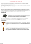
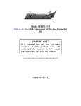
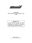
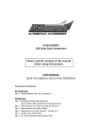
Model JEEPKIT-1
Bolt-on
on Air Horn & Compressor Kit for Jeep Wrangler JK
IMPORTANT:
It is essential that you
y
and any other
operator of this product read and
understand the contents of this manual
before installing and using this product.
SAVE THIS MANUAL FOR FUTURE REFERENCE
USER MANUAL
Model JEEPKIT-1
Components:
1
1
1
1
1
1
1
1
1
2.5 Liter, 4-port air tank
Model 6250RC compressor
Dual trumpet air horn
Installation wiring & connector kit
Compressor installation hardware (Package #1 - inside compressor box)
JEEPKIT mounting hardware (Package #2)
Compressor/Tank mounting bracket
Horn mounting bracket
12’ length air tubing
PARTS PACKAGES
Package #1 – Compressor Installation Hardware
Qty 4 13/64” Nuts, bolts, washers & locking washers
(Compressor mounting hardware)
Qty 1 Remote Mount Air Filter Assembly
Qty 1 Remote mount air filter fitting for air filter connection
Qty 1 Replacement air filters
Qty 1 Leader Hose Bracket Clip
Qty 1 Air line for remote mounting air filter
Package #2 – Jeep Kit bracket and tank hardware
Qty 6 5” bolts
Qty 6 Nyloc nuts
Qty 3 Rear mount plates
Qty 4 Nuts, bolts, and washers – (Air tank mounting hardware)
Compressor/Tank – General Information
Your Jeep Kit comes complete with a model 6250RC, 9% duty cycle compressor and a 2.5 liter
air tank. Please follow the installation instructions that follow in order to enjoy the best use of
your air horn kit.
CAUTION - To reduce risk of electrical shock or electrocution:
• Do not disassemble the compressor. Do not attempt repairs or modifications. Refer to
qualified service agencies for all service and repairs.
• Do not use this product in an area where it can fall or be pulled into water or liquids.
• Do not reach for this product if it has fallen into liquid.
• Use this compressor with 12-volt DC systems only.
• This product should never be left unattended during use.
IMPORTANT:
• Tank is rated for 120 PSI maximum working pressure.
• Tank is not to be used as a breathing device.
• Bleed pressure from tank before servicing or adding attachments.
• Use only attachments or tools rated for 120 PSI working pressure or less.
• Apply sealant or Teflon tape to threads of fittings prior to assembly and tighten each part
with a wrench.
• Do not over tighten, since brass threads can be stripped.
• Always release air from tank before servicing.
• To remove accumulated condensation inside the tank, disconnect power from the compressor
and release the pressurized air by sounding the horns. Unbolt the air tank, then drain water
by removing the drain plug at the bottom of the tank. Once the water is drained, replace the
plug and re-mount the tank. Use Teflon thread tape to ensure a good seal.
CAUTION:
DO NOT PRESSURIZE YOUR TANK UNTIL YOU HAVE INSTALLED ALL
NECESSARY PORT FITTINGS AND ACCESSORIES.
FAILURE TO DRAIN TANK AND REMOVE CONDENSATION WILL CAUSE TANK
TO RUST PREMATURELY.RUSTED TANKS CAN FAIL CAUSING EXPLOSIONS OR
FATAL INJURIES. DISCARD TANK IMMEDIATELY IF IT IS RUSTED.
Compressor/Tank Installation
Included in your kit is a vehicle-specific mounting bracket for the compressor and air tank. The
bracket clamps around the horizontal beam located above the rear differential.
Preparation
1. Locate the horizontal beam above the rear differential. There is a small wiring harness,
attached to the top of the support with two plastic clips. Remove the clips to allow free
movement of the wiring harness. It is not necessary to salvage the clips – they will not
be re-used (see photo 1).
2. Attach the compressor to the vehicle-specific mounting bracket using the bolts in
Package 2. The compressor should be mounted with the piston on the driver’s side of
the vehicle, facing away from the tank mounting location. Bring the bolts up through the
bottom of the mounting plate and have the nuts on the top. Do not mount the tank yet.
3. Insert two 5” mounting bolts into each rear mount plate (see photo 2).
Photo 1 – Horizontal beam with wiring harness clips
removed
Photo 2 – Rear Mount Plates with bolts inserted
Mounting the compressor/tank bracket
1. Work from the driver’s side of the vehicle and slide all three rear mount plate/mounting
bolt sub-assemblies onto the horizontal beam. The rear mount plates should be towards
the rear of the vehicle, the bolts should be extending over and below the beam, pointing
toward the front of the vehicle (see photo 3). As each sub-assembly is positioned over
the beam, slide it towards the passenger side of the vehicle so that the three subassemblies are spaced at roughly the same intervals as the three sets of mounting holes on
the bracket (see photo 4). Make sure the wiring harness you detached from the beam
earlier is lying on TOP of the bolts and not running under the bolts! Helpful Tip: Using
electrical tape to temporarily hold the bolts on the rear mount plates will make this task
easier.
Photo 3 – Slide the rear mount plate/bolt assemblies
over the beam. Work from the driver’s side and slide
the assemblies towards the passenger’s side
Photo 4 – All three rear mount plate/bolt assemblies in
place.
2. Position the bracket in front of the beam, then align the rear mount/bolt assemblies so that
the bolts pass through the mounting holes in the bracket. Hand tighten the six Nyloc nuts
onto the bolts.
3. Position the entire bracket assembly towards the passenger side of the beam. There is a
welded joint at the end of the beam – the bracket should be butted up against that weld.
Do not try to attach the bracket over the weld (see photos 5 & 6)
4. Using an 11mm gear wrench or a ratchet with a 6” extension, tighten the six Nyloc nuts.
Alternate between top and bottom so that the rear mount plates sit flush against the back
of the beam and the bolts sit flush on the top and bottom of the beam. Use a wrench to
hold the bolt heads while tightening.
5. Attach a short section (approx 12-18”) of the black tubing in the compressor accessory
package to the air intake on the front of the compressor. Route the other end into the
existing opening in the floor brace just above the compressor.
Photo 5 – Compressor on mounting bracket, as seen
from the front of the vehicle.
Photo 6 – Mounting bracket, as seen from underneath.
Making the air connections
1. Temporarily slip the emergency brake cables out of their support to allow room for
installing the air tank. Position the air tank on top of the mounting bracket with the
fittings facing the driver’s side of the vehicle and the compressor. Do not attach the tank
to the bracket yet (see photo 7).
2. Remove the red rubber plug from the end of the steel braided leader hose on the
compressor and apply Teflon thread tape to the threads on the check valve at the end of
the leader hose.
3. Make a loop with the leader hose and position the hose between the compressor body and
the back of the bracket (see photo 8).
4. Thread the leader hose into the tank and tighten with a wrench. It is important that the
connection is snug, but not over tightened. When the brass female adapter on the tank
starts turning, you’ve tightened the leader hose enough.
5. Connect the air tube to the compression fitting on the tank. For best results, make sure the
end of the tube is cut clean and square. Route the tube over the top of the bracket that
holds the Jeep EVAP canister.
Photo 7 – Emergency brake cable support
Photo 8 – Air tank positioned on mounting bracket.
Note how the braided steel leader hose is looped
between the compressor body and the mounting bracket.
Mounting the air horn
1. Locate the EVAP canister under the vehicle. It is towards the driver’s side, just forward
of the rear axle (see photo 9).
2. Remove the two 5/8” bolts for the EVAP canister mounting bracket.
3. Use the mounting bolts found inside the horn box to attach the horns to the horn
mounting bracket
4. Cut your tubing to length, making sure the end is clean and square. Connect the air line
to the solenoid valve, then slip the horn mounting bracket UNDER the EVAP canister
bracket and align the holes. Re-install the 5/8” bolts through the EVAP canister mount
and the horn bracket (see photo 10)
Photo 9 – EVAP canister. Note the two 5/8” mounting
bolts
Photo 10 – Air horn bracket mounted under EVAP unit
bracket
Pre-wiring
1. Disconnect ground cable from vehicle’s battery.
2. Ground the compressor black wire. The nut that secures the emergency brake cable
support just forward and above the rear differential is a good grounding point.
3. Your wiring kit includes red, yellow, purple and black wires that will need to be run the
length of the vehicle. Run the red and yellow wires from the battery area (passenger
side), across the engine compartment, and back to the compressor/tank.
4. Run the black and purple wires to the back from the area of the ignition switch harness
(under the steering column). The black wire will terminate at the air horns, the purple
wire will run all the way back to the compressor/tank.
Be sure to keep your wiring away from heat sources such as the exhaust!
Wiring Connections
1. Use the relay including in your wiring package to supply power to the compressor.
Mount the relay near the battery and wire as follows:
•
•
•
•
Pin 30 – to the 10 gauge red wire that runs the length of the vehicle and attaches to
the red wire on the compressor
Pin 85 – to the yellow wire runs the length of the vehicle to one side of the pressure
switch (it does not matter which terminal)*
Pin 86 – to ground
Pin 87 – to one end of the fuse holder (cut the loop)
* before attaching spade connectors to the ends of the wires that connect to the
pressure switch, pass the wires through the opening in the black rubber pressure
switch cover. Slide the cover over the pressure switch once the connections have
been completed.
2. Connect the end of the purple wire at the compressor/tank to the open terminal on the
pressure switch. Connect the other end of the purple wire to the 12v+ ignition wire in the
ignition switch harness.
3. The black wire will be your horn trigger. If you want to activate your horn using the
pushbutton supplied with the kit, connect one side of the pushbutton to ground and the
other side of the pushbutton to the black wire. If you want to use your factory horn
switch instead of the pushbutton, connect the black wire to the vehicle (-) horn wire,
located in the ignition switch harness. In either scenario, the other end of the black wire
should be connected to one of the wires (it doesn’t matter which) coming out of the
solenoid valve on the air horn.
4. Use a leftover section of your black wire to connect the remaining wire on the air horn
solenoid valve to +12v ignition. You can use the +12v ignition you already have
running to the back of the vehicle via the purple wire.
5. Connect the remaining end of the fuse holder to the + terminal of the battery or the
‘power point’ on the corner of the fuse box, in front of the battery.
6. Insert the fuse in the fuse holder to complete your wiring
7. Use the wire loom supplied with the kit to protect your wiring!
8. Use the supplied wire ties to secure the factory wiring harness that was detached earlier
to the holes on the compressor mounting bracket.
Mounting the air tank
1. After all electrical connections have been completed, pressure test the tank before bolting
it to the bracket. To pressure test the tank, complete your wiring and turn on the ignition
to run the compressor. Once the pressure switch shuts the compressor off, spray soapy
water on all the air connections at the tank. If you see bubbles, tighten the connection
slightly or add more Teflon tape.
2. Once you have pressure tested the system, the tank can be mounted to the bracket. Use
the four nuts, bolts and washers included in hardware package #1. Install the bolts from
the top downward. Helpful Tip: The passenger side rear bolt will be difficult to access.
Use a piece of electrical tape to temporarily hold the bolt into the tank’s foot when doing
your final positioning of the tank on the bracket.
COMPRESSOR OPERATING INSTRUCTIONS
IMPORTANT: The compressor has a maximum working pressure of 120 PSI and is capable of
9% duty cycle. It is designed for use with air horns, air bags and other accessories that utilize the
compressed air stored in the tank. Always operate the compressor at or below the MAXIMUM
PRESSURE RATING of the compressor. Operation exceeding maximum pressure ratings and or
duty cycle will result in damage to air compressor.
1. Your air compressor is equipped with an AUTOMATIC THERMAL OVERLOAD
PROTECTOR. This feature is designed to protect the air compressor from overheating and
causing permanent damage to your air compressor. The thermal overload protector will
automatically cut off power to your air compressor should the internal operating temperature
of the air compressor rise above safe levels during excessive use.
2. Should your air compressor automatically shut off while in use; do not attempt to restart the
air compressor. Turn power switch to the air compressor to the OFF position. The automatic
thermal overload protector will automatically reset when internal temperature of the air
compressor drops below safe level. After allowing air compressor to cool off for about 30
minutes, you can safely resume use of the air compressor by turning on the air compressor.
3. To prevent discharge of your vehicle’s battery and to provide peak performance, we strongly
recommend that you keep the vehicle’s engine running while using the air compressor.
4. ONLY OPERATE THE AIR COMPRESSOR IN WELL-VENTILATED AREAS.
Compressor Maintenance & Repairs
1. Periodically check all electrical and fitting connections. Clean and tighten as needed.
2. Periodically check all mounting screws. Tighten as needed.
3. Replace air filter element periodically. Replacement frequency depends on operating
frequency and operating environment. For frequent use in dusty environment, you should
replace air filter element more often.
4. Regularly clean dust and dirt from compressor.
5. Your air compressor is equipped with permanently lubricated, maintenance free motor.
Never lubricate compressor.
6. Repairs should be performed by Manufacturer or Manufacturer’s Authorized Service
Agencies only.
CAUTION: Never touch the air compressor or fittings connected to the air compressor with bare
hands during or immediately after use. Leader hose and fittings will become very HOT during
and after use.
Kleinn Model JEEPKIT-1
LIMITED WARRANTY
Kleinn Automotive Air Horns warrants this
product, when properly installed and under
normal conditions of use, to be free from
defects in workmanship and materials for a
period of one year from provided date of
purchase. To receive a replacement or for
repairs,
airs, return the complete unit to retailer from
whom it was purchased along with proof of
purchase.
Returns should be made within the time period
and conditions of the retailer’s policy for
exchanges. If you are unable to contact your
dealer, contact Kl
Kleinn directly for repairs or
replacement at our option.
Kleinn Automotive Accessories
P.2094 N. Dragoon St
Tucson, AZ 85745
Phone: (520) 579-1531
Fax: (520) 579-1528
[email protected]