1
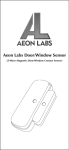
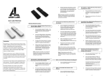
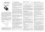
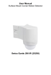
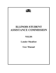
IMPORTANT:
A licensed electrician with knowledge and
understanding of electrical systems and electrical
safety should complete the electrical installation
inside the main circuit box (usually located outside of
your house).
1. Live - Hot wire (Black wire) Connect to Live terminal of Micro Smart Energy Switch G2.
2. Neutral (White wire) Note! If this wire is not present in the box, a neutral wire must
be pulled into the box.
3. Load wire - Connect to Load terminal of Micro Smart Energy Switch G2.
4. Signal connection - Using two
18 AWG copper wires, connect
Make sure that the ends of the wires from the
the terminals of the wall switch
wall box are straight (cut if neccessary).
to Micro Smart Energy Switch
G2 as shown.
Remove insulation from each wire and the wall
5. Side wire connection
box as shown.
4
In-Wall Electrical Installation Instructions:
Micro Switch G2
Micro Smart Energy Switch G2
(Generation 2)
OFF
OFF
OFF
OFF
OFF
OFF
2
ON
1
OFF
ON
OFF
ON
OFF
ON
Step 4
Load
Load
L L
Mounting In Wall Box.
1. Position all wires to provide room for the device. Place Micro Smart
Energy Switch G2 inside the wall box towards the back of the box.
2. Position the antenna towards the back of the box, away from all other
wiring.
3. Reinstall the wall switch to the wall box.
4. Reinstall the cover plate onto the wall box.
2
1
1. Remove the two screws securing the cover plate.
2. Remove the wall switch cover plate.
3. Remove the two screws securing the wall switch to the wall
box. Disconnect both wires from the wall switch.
3
Troubleshooting: If the Aeotec Micro Smart Energy Switch G2 was
not successfully included into any Z-Wave network, the LED will continually
blink slowly. If the Aeotec Micro Smart Energy Switch G2 was
successfully included to a Z-Wave network, the Status Indication LED
will either be solid on or off depending on if the switch is on or off.
Removing/Resetting the Micro Smart Energy
Switch G2 from your Z-Wave Network
4
1
e
ov
m
Re
de
arn
clu
Le
2
Remove
1
Step 5
Restore Power
Restore power at the circuit breaker or fuse.
Installation is complete.
The Aeotec Micro Smart Energy Switch G2 is a
low-cost Z-Wave appliance module specifically used
to enable Z-Wave command and control (on/
off) for existing in-wall switches. It can also report
immediate wattage consumption or kWh energy
usage over a period of time.
Preparing and Connecting Wires
The Aeotec Micro Smart Energy Switch G2 must first be powered
by a 3-wire system in order to operate. The wiring diagram
is as follows:
Note: The "3V Out" terminal should be used only with the Aeon
Micro Touch.
Cut wire if
neccessary
It also is a repeater in the Z-Wave network.
Acting as a bridge for communication, it will
forward Z-Wave command messages to their
destinations if the originating controller is out of
range from the destination node.
0.27”
(7mm)
Strip Gage
(measure bare
here)
Diagram
ON
ON
ON
ON
ON
ON
ON
ON
ON
ON
ON
ON
Note: The LED on the Micro Smart Energy Switch G2 will
blink if it is currently not paired into a Z-Wave network.
Adding/Including/Pairing the Micro Smart Energy
Switch G2 into a Z-Wave Network
3V
Out Wall Switch
Load
L L
Load
AC Power
N N
Note: To remove the Aeotec Micro Smart Energy Switch
G2 from other controllers, please consult the operation
manual for these controllers on how to remove Z-Wave
products from an existing network.
2
While the Micro Smart Energy Switch G2 is powered in a 3-wire
system, the external switch/button can be toggled 10 times in
quick succession to initiate removing from the Z-Wave network.
Or the internal button can be pushed to initiate pairing into the
Z-Wave network if Micro Smart Energy Switch G2 was not put
into in-wall box.
The Aeotec Micro Smart Energy Switch G2 must be paired
(included) into a Z-Wave network before it can receive
Z-Wave commands to turn on/off and report its energy usage.
The Micro Smart Energy Switch G2 can only communicate
to devices within it’s own Z-Wave network.
Out
Wall Switch
AC Power
N N
ON
Z-Wave Network Instructions:
1
Load
ON
3V
Step 3
te
cia
so
As
3
Press the button labeled “Remove” on
the Aeotec Minimote to begin the Z-Wave
removal process.
4
In
Introduction:
By taking advantage of the Z-Wave mesh
network, commands can be routed to their
destination via intermediary “listening” Z-Wave
products. Products that are Z-Wave certified can
be used and communicate with other Z-Wave
certified devices.
AC Power
N N
Dismounting In Wall Box.
(In-Wall Z-Wave Appliance Module w/ Energy Monitor)
The wireless module is powered from the mains
supply and is a three-wire design which requires
a neutral connection. In the event of power
failure, non-volatile memory retains all
programmed information relating to the units
operating status.
While the Micro Smart Energy Switch G2 is powered in a 3-wire
system, the external switch/button can be toggled to initiate
pairing into the Z-Wave network. Or the internal button can be
pushed to initiate pairing into the Z-Wave network if the Micro
Smart Energy Switch G2 was not put into in-wall box.
5
3
OFF
2
Out
Wall Switch
Step 2
IMPORTANT: The electricity to the circuit must be shut off
during installation for safety and to ensure that wires are not
short circuited during installation thus causing damage to
the Micro Module.
3V
Step 1
Note: To include the Aeotec Micro Smart Energy Switch G2
with other controllers, please consult the operation manual
for these controllers on how to include Z-Wave products
into an existing network.
Press the button labeled “Include” on
the Aeotec Minimote to begin the
Z-Wave inclusion process.
Load
L L
e
ov
m
Re
de
arn
clu
Le
In
Include
te
cia
so
As
Troubleshooting: If the Aeotec Micro Smart Energy Switch G2 was
removed from the Z-Wave network, the Status Indication LED will be
blinking. If the Aeotec Micro Smart Energy Switch G2 was not successfully
removed from the Z-Wave network, the Status Indication LED will either
be solid on or off depending on if the switch is on or off.
Note: If Micro Smart Energy Switch G2 was not put into in-wall box,
Another way to reset Aeotec Micro Smart Energy Switch G2 is
pressing and holding the button which is on Micro Smart Energy
Switch G2 20 seconds.
Continued
Turning On/Off the Micro Smart Energy Switch G2
Use any of the below methods to allow power through or cut power from
the Micro Smart Energy Switch G2.
• Through the usage of Z-Wave commands built into Z-Wave certified
controllers and gateways. (The specific Z-Wave commands supporting this
function are the Basic Command Class, Binary Switch Command Class,
and Scene Activation Command Class) Please consult the operation
manual for these controllers for specific instructions on controlling the
Micro Smart Energy Switch G2.
• Pressing the button on the Micro Smart Energy Switch G2 will toggle
power flow (on/off) through the Micro Smart Energy Switch G2.
Change Mode on the External Switch/Button
Control
• The Aeotec Micro Smart Energy Switch G2 is set to be controlled
via 2-state(flip/flop) external wall switch by default. Pushing and
holding the button 6 seconds on the Micro Smart Energy Switch G2
will swap between this default mode and the momentary push button
external wall switch mode.
• Through the usage of Z-Wave command built into Z-Wave certified
controllers and gateways. (The specific Z-Wave command supporting
this funtion is Configuration Command Class) Please consult the
operation manual for these controllers for specific instructions on
changing external wall switch mode of the Aeotec Micro Smart Energy
Switch G2.
Monitoring Energy Consumption
The Aeotec Micro Smart Energy Swtich G2 can report wattage energy
usage or kWh energy usage to a Z-Wave gateway or controller when
requested. If this function is supported by the gateway/controller, the
energy consumption will be displayed in the user interface of the
gateway/controller. (The specific Z-Wave commands supporting energy
monitoring are the Meter Command Class. Automatic reports are sent
to association group 1, which is setup via the Association Command
Class.) Please consult the operation manual for these gateways/controllers
for specific instructions on monitoring the Micro Smart Energy Switch G2.
Note: The Micro Switch G2 (without the words “Smart Energy”) does
not have the ability to monitor energy consumption.
Technical Specifications
•
•
UL NOTICE (For USA):
Warranty
USA: 120V 60Hz input, 1200W or 10A max output.
EU/AU/IN/BR/CN: 230V 50Hz input, 2300W or 10A max output.
Aeotec warrants to the original purchaser of Products that for the
Warranty Period (as defined below), the Products will be free from
material defects in materials and workmanship. The foregoing warranty
is subject to the proper installation, operation and maintenance of the
Products in accordance with installation instructions and the operating
manual supplied to Customer. Warranty claims must be made by
Customer in writing within thirty (30) days of the manifestation of a
problem. Aeotec' sole obligation under the foregoing warranty is, at
Aeotec' option, to repair, replace or correct any such defect that was
present at the time of delivery, or to remove the Products and to refund
the purchase price to Customer.
The "Warranty Period" begins on the date the Products is delivered and
continues for 12 months.
Any repairs under this warranty must be conducted by an authorized
Aeotec service representative and under Aeotec’ RMA policy. Any
repairs conducted by unauthorized persons shall void this warranty.
Excluded from the warranty are problems due to accidents, acts of God,
civil or military authority, civil disturbance, war, strikes, fires, other
catastrophes, misuse, misapplication, storage damage, negligence,
electrical power problems, or modification to the Products or its
components.
Aeotec does not authorize any person or party to assume or create for it
any other obligation or liability in connection with the Products except as
set forth herein.
Aeotec will pass on to Customer all manufacturers’ Material warranties
to the extent that they are transferable, but will not independently
warrant any Material.
Customer must prepay shipping and transportation charges for returned
Products, and insure the shipment or accept the risk of loss or damage
during such shipment and transportation. Aeotec will ship the repaired or
replacement products to Customer freight prepaid.
Customer shall indemnify, defend, and hold Aeotec and Aeotec’
affiliates, shareholders, directors, officers, employees, contractors,
agents and other representatives harmless from all demands, claims,
actions, causes of action, proceedings, suits, assessments, losses,
damages, liabilities, settlements, judgments, fines, penalties, interest,
costs and expenses (including fees and disbursements of counsel) of
every kind (i) based upon personal injury or death or injury to property to
the extent any of the foregoing is proximately caused either by a
defective product (including strict liability in tort) or by the negligent or
willful acts or omissions of Customer or its officers, employees,
subcontractors or agents, and/or (ii) arising from or relating to any actual
or alleged infringement or misappropriation of any patent, trademark,
mask work, copyright, trade secret or any actual or alleged violation of
any other intellectual property rights arising from or in connection with
the products, except to the extent that such infringement exists as a
result of Aeotec‘ manufacturing processes.
IN NO EVENT SHALL AEOTEC BE LIABLE FOR ANY INDIRECT,
INCIDENTAL,
PUNITIVE,
SPECIAL OR
CONSEQUENTIAL
DAMAGES, OR DAMAGES FOR LOSS OF PROFITS, REVENUE, OR
USE INCURRED BY CUSTOMER OR ANY THIRD PARTY, WHETHER
IN AN ACTION IN CONTRACT, OR TORT, OR OTHERWISE EVEN IF
ADVISED OF THE POSSIBILITY OF SUCH DAMAGES. AEOTEC’S
LIABILITY AND CUSTOMER’S EXCLUSIVE REMEDY FOR ANY
CAUSE OF ACTION ARISING IN CONNECTION WITH THIS
AGREEMENT OR THE SALE OR USE OF THE PRODUCTS,
WHETHER BASED ON NEGLIGENCE, STRICT LIABILITY, BREACH
OF WARRANTY, BREACH OF AGREEMENT, OR EQUITABLE
PRINCIPLES, IS EXPRESSLY LIMITED TO, AT AEOTEC’S OPTION,
REPLACEMENT OF, OR REPAYMENT OF THE PURCHASE PRICE
FOR THAT PORTION OF PRODUCTS WITH RESPECT TO WHICH
DAMAGES ARE CLAIMED. ALL CLAIMS OF ANY KIND ARISING IN
CONNECTION WITH THIS AGREEMENT OR THE SALE OR USE OF
PRODUCTS SHALL BE DEEMED WAIVED UNLESS MADE IN
WRITING WITHIN THIRTY (30) DAYS FROM AEOTEC’S DELIVERY,
OR THE DATE FIXED FOR DELIVERY IN THE EVENT OF NONDELIVERY.
THE INDEMNITY AND WARRANTY IN ABOVE ARE EXCLUSIVE AND
IN LIEU OF ALL OTHER INDEMNITIES OR WARRANTIES, WHETHER
EXPRESS OR IMPLIED, INCLUDING THE IMPLIED WARRANTIES
OF MERCHANTABILITY AND FITNESS FOR A PARTICULAR
PURPOSE.
FCC NOTICE (For USA):
THE MANUFACTURER IS NOT RESPONSIBLE FOR ANY RADIO OR
TV INTERFERENCE CAUSED BY UNAUTHORIZED MODIFICATIONS
TO THIS EQUIPMENT. SUCH MODIFICATIONS COULD VOID THE
USER’S AUTHORITY TO OPERATE THE EQUIPMENT.
STORE INDOORS WHEN NOT IN USE. SUITABLE FOR DRY
LOCATIONS. DO NOT IMMERSE IN WATER. NOT FOR USE WHERE
DIRECTLY EXPOSED TO WATER.
This device complies with Part 15 of the FCC Rules. Operation is subject
to the following two conditions:
1. This device may not cause harmful interference, and
2.This device must accept any interference received, including
interference that may cause undesired operation. This equipment has
been tested and found to comply with the limits for a Class B digital
device, pursuant to part 15 of the FCC Rules. These limits are designed
to provide reasonable protection against harmful interference in a
residential installation. This equipment generates, uses and can radiate
radio frequency energy and, if not installed and used in accordance with
the instructions, may cause harmful interference to radio communications. However, there is no guarantee that interference will not occur in
a particular installation. If this equipment does cause harmful
interference to radio or television reception, which can be determined by
turning the equipment off and on, the user is encouraged to try to correct
the interference by one or more of the following measures:
•Reorient or relocate the receiving antenna.
•Increase the separation between the equipment and receiver.
•Connect the equipment into an outlet on a circuit different from that
to which the receiver is connected.
•Consult the dealer or an experienced radio/TV technician for help.
1. Install only in a UL Listed junction box sized 3X2X2.75 inch
(75X50X70mm) or larger,minimum Volume 14 in3 (230 cm 3 )
2. Use Copper Conductors Only.
3. CAUTION - Risk of Electric Shock - More than one disconnect switch
may be required to de - energize the equipment before servicing.
4. WARNING - This device shall not be used in combination with a wall
switch controlling a receptacle.
Warning:
Do not dispose of electrical appliances as unsorted municipal waste,
use separate collection facilities.
Contact your local government for information regarding the collection
systems available.
Certifications (regional):