1
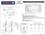
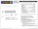
DUAL VOLTAGE, ADJUSTABLE
SPEED, SCR REGENERATIVE
DRIVE FOR PERMANENT MAGNET
DC BRUSH MOTORS
User’s Manual
GS60U
Safety Warnings
SHOCK
HAZARD
AVOID
HEAT
KEEP
DRY
Contents
AVOID
VIBRATION
• This symbol
denotes an important safety tip or warning.
Please read these instructions carefully before performing any
of the procedures contained in this manual.
• DO NOT INSTALL, REMOVE, OR REWIRE THIS
EQUIPMENT WITH POWER APPLIED. Have a qualified
electrical technician install, adjust and service this equipment.
Follow the National Electrical Code and all other applicable
electrical and safety codes, including the provisions of the
Occupational Safety and Health Act (OSHA), when installing
equipment.
• Reduce the chance of an electrical fire, shock, or explosion by
proper grounding, over-current protection, thermal protection,
and enclosure. Follow sound maintenance procedures.
WARNING
It is possible for a drive to run at full speed as
a result of a component failure. Manufacturer
strongly recommends the installation of a master
switch in the main power input to stop the drive in an
emergency.
Circuit potentials are at 115 VAC or 230 VAC above
Earth ground. Avoid direct contact with the printed
circuit board or with circuit elements to prevent the
risk of serious injury or fatality. Use a non-metallic
screwdriver for adjusting the calibration trimpots.
Use approved personal protective equipment and
insulated tools if working on this drive with power
applied.
2
Regenerative Drives . . . . . . . . . . . . . . . . . . . . . . . . . . . . . . . . . 3
Specifications . . . . . . . . . . . . . . . . . . . . . . . . . . . . . . . . . . . . . . 3
Dimensions . . . . . . . . . . . . . . . . . . . . . . . . . . . . . . . . . . . . . . . . 4
Installation . . . . . . . . . . . . . . . . . . . . . . . . . . . . . . . . . . . . . . . . 4
Mounting . . . . . . . . . . . . . . . . . . . . . . . . . . . . . . . . . . . . . . . . . 4
Wiring . . . . . . . . . . . . . . . . . . . . . . . . . . . . . . . . . . . . . . . . . . . . 5
Shielding guidelines . . . . . . . . . . . . . . . . . . . . . . . . . . . . . . . 5
Heat sinking . . . . . . . . . . . . . . . . . . . . . . . . . . . . . . . . . . . . . . . 5
Line fusing . . . . . . . . . . . . . . . . . . . . . . . . . . . . . . . . . . . . . . . . 5
Speed adjust potentiometer . . . . . . . . . . . . . . . . . . . . . . . . . . . 5
Connections . . . . . . . . . . . . . . . . . . . . . . . . . . . . . . . . . . . . . . . 6
Power, fuse and motor connections . . . . . . . . . . . . . . . . . . . 6
Voltage follower (isolated signal) . . . . . . . . . . . . . . . . . . . . . . . 7
Line voltage switches . . . . . . . . . . . . . . . . . . . . . . . . . . . . . . . . 7
Armature voltage switch . . . . . . . . . . . . . . . . . . . . . . . . . . . . . . 7
Feedback selector switch . . . . . . . . . . . . . . . . . . . . . . . . . . . . . 7
Operation . . . . . . . . . . . . . . . . . . . . . . . . . . . . . . . . . . . . . . . . . . 8
Before applying power: . . . . . . . . . . . . . . . . . . . . . . . . . . . . . . 8
Startup and shutdown . . . . . . . . . . . . . . . . . . . . . . . . . . . . . . . 8
To start the drive: . . . . . . . . . . . . . . . . . . . . . . . . . . . . . . . . . 8
Starting and Stopping Methods . . . . . . . . . . . . . . . . . . . . . . . . 8
Automatic restart upon power restoration . . . . . . . . . . . . . . . 8
Decelerate to a stop . . . . . . . . . . . . . . . . . . . . . . . . . . . . . . . 8
Coast to a stop . . . . . . . . . . . . . . . . . . . . . . . . . . . . . . . . . . . 8
Regenerative brake . . . . . . . . . . . . . . . . . . . . . . . . . . . . . . . 8
Invert Inhibit and Invert Enable . . . . . . . . . . . . . . . . . . . . . . . 9
Calibration . . . . . . . . . . . . . . . . . . . . . . . . . . . . . . . . . . . . . . . . 10
MINIMUM SPEED (MIN SPD) . . . . . . . . . . . . . . . . . . . . . . . . 10
MAXIMUM SPEED (MAX SPD) . . . . . . . . . . . . . . . . . . . . . . . 10
FORWARD TORQUE (FWD TQ) . . . . . . . . . . . . . . . . . . . . . . 10
REVERSE TORQUE (REV TQ) . . . . . . . . . . . . . . . . . . . . . . . 11
IR COMPENSATION (IR COMP) . . . . . . . . . . . . . . . . . . . . . . 11
FORWARD ACCELERATION (FWD ACC) . . . . . . . . . . . . . . 11
REVERSE ACCELERATION (REV ACC) . . . . . . . . . . . . . . . 11
DEADBAND (DB) . . . . . . . . . . . . . . . . . . . . . . . . . . . . . . . . . . 12
TACH GENERATOR (TACH) . . . . . . . . . . . . . . . . . . . . . . . . . 12
Application Notes . . . . . . . . . . . . . . . . . . . . . . . . . . . . . . . . . . 13
Connections to GoldSpec™ GS600 . . . . . . . . . . . . . . . . . . . . 13
FWD-REV switch . . . . . . . . . . . . . . . . . . . . . . . . . . . . . . . . . . 13
FWD-STOP-REV switch . . . . . . . . . . . . . . . . . . . . . . . . . . . . . 13
Independent Adjustable Speeds . . . . . . . . . . . . . . . . . . . . . . 13
Independent forward and reverse speeds . . . . . . . . . . . . . . . 14
Independent forward and reverse speeds
with FWD-STOP-REV switch . . . . . . . . . . . . . . . . . . . . . . . . . 14
Troubleshooting . . . . . . . . . . . . . . . . . . . . . . . . . . . . . . . . . . . 14
Before applying power . . . . . . . . . . . . . . . . . . . . . . . . . . . . . . . . 14
GoldSpec™ User’s Manual
1
Specifications
Specifications
Model
Regenerative Drives
Armature
Current Range
(ADC)
Armature
Horsepower
5.0*
1/4 - 1/2*
0 - 90
5.0**
1/4 – 1**
0 – 180
GS60U
Most non-regenerative, variable speed, DC drives control
current flow to a motor in one direction. The direction of
current flow is the same direction as the motor rotation. Non-regenerative drives operate in Quadrant 1, and also in
Quadrant 3 if the drive is reversible (see Figure 1, below).
Motors must stop before reversing direction. Unless
dynamic braking is used, non-regenerative drives cannot
decelerate a load faster than coasting to a lower speed.
Voltage
Range
(VDC)
* Max. Armature Current = 10 ADC and
Max. Horsepower = 1 hp when mounted to heat sink kit part number GS223-0159.
** Max. Armature Current = 10 ADC and
Max. Horsepower = 2 hp when mounted to heat sink kit part number GS223-0159.
AC Line Voltage
115 VAC / 230 VAC, ±10%, 50/60 Hz, single phase
Form Factor
1.37 at base speed
Acceleration Time Range
0.5 – 6 seconds
Deceleration Time Range
0.5 – 6 seconds
Analog Input Voltage Range
(signal must be isolated; S0 to S2)
Input Impedance (S0 to S2)
Regenerative drives operate in two additional quadrants:
Quadrant 2 and Quadrant 4. In these quadrants, motor
torque is in the opposite direction of motor rotation.
0 to +/- 10 VDC
vi
30 kohms
This allows regenerative drives to reverse a motor without
contactors or switches, to control an overhauling load, and
Regenerative Drives
to decelerate a load faster than it would take to coast to a
lower speed.
Load Regulation
with Armature Feedback
with Tachogenerator Feedback
Vibration
1% base speed
0.1% base speed
0.5G max. (20–50 Hz)
0.1G max. (> 50 Hz)
Ambient Temperature Range
Weight
10°C – 55°C
1.1 lb
Tables
Table 1. Recommended Line Fuse Sizes . . . . . . . . . . . . . . . . . . . . . . . . . 5
Quadrant II
Quadrant I
Quadrant III
Quadrant IV
Illustrations
Figure 1 Four Quadrant Operation . . . . . . . . . . . . . . . . . . . . . . . . . . . . . . 3
Figure 2 GS60U Dimensions. . . . . . . . . . . . . . . . . . . . . . . . . . . . . . . . . . . 4
Figure 4 Speed Adjust Potentiometer. . . . . . . . . . . . . . . . . . . . . . . . . . . . 5
Figure 5 Screw Terminal Block . . . . . . . . . . . . . . . . . . . . . . . . . . . . . . . . . 6
Figure 6 Cage-Clamp Terminal Block. . . . . . . . . . . . . . . . . . . . . . . . . . . . 6
Figure 7 Power and Motor Connections (Bottom Board). . . . . . . . . . . . . 6
Figure 8 Speed Adjust Potentiometer Connections. . . . . . . . . . . . . . . . . . 7
Figure 9 Voltage Follower Connection. . . . . . . . . . . . . . . . . . . . . . . . . . . 7
Figure 10 Line Voltage Switches (bottom board). . . . . . . . . . . . . . . . . . . 7
Figure 11 Armature Voltage and Feedback
Selector Switch Locations (top board). . . . . . . . . . . . . . . . . . . . . . . . . . . . 7
Figure 13 RUN/STOP Switch . . . . . . . . . . . . . . . . . . . . . . . . . . . . . . . . . . 8
Figure 14 INHIBIT / ENABLE Terminal TB503
and JP502 Locations. . . . . . . . . . . . . . . . . . . . . . . . . . . . . . . . . . . . . . . . . 9
Figure 15 INHIBIT Settings. . . . . . . . . . . . . . . . . . . . . . . . . . . . . . . . . . . . 9
Figure 16 ENABLE Settings . . . . . . . . . . . . . . . . . . . . . . . . . . . . . . . . . . . 9
Figure 17 GS60U Calibration Trimpot Locations. . . . . . . . . . . . . . . . . . . 10
Figure 18 Deadband Settings. . . . . . . . . . . . . . . . . . . . . . . . . . . . . . . . . 12
Figure 19 Typical FWD TQ, REV TQ, and
IR COMP Trimpot Settings . . . . . . . . . . . . . . . . . . . . . . . . . . . . . . . . . . . 13
Figure 21 GS60U Connections to GS600. . . . . . . . . . . . . . . . . . . . . . . . 13
Figure 22 Forward-Reverse Switch. . . . . . . . . . . . . . . . . . . . . . . . . . . . . 13
Figure 23 Forward-Stop-Reverse Switch . . . . . . . . . . . . . . . . . . . . . . . . 13
Figure 24 Independent Adjustable Speeds
(Forward Direction). . . . . . . . . . . . . . . . . . . . . . . . . . . . . . . . . . . . . . . . . 13
Figure 25 Independent Forward and Reverse Speeds. . . . . . . . . . . . . . 14
Figure 26 Independent Forward and Reverse Speeds with
a Forward-Stop-Reverse Switch. . . . . . . . . . . . . . . . . . . . . . . . . . . . . . . 14
GS60U
MOTOR
ROTATION
MOTOR
TORQUE
NOTE: ARROWS IN SAME DIRECTION = MOTOR ACTION
ARROWS IN OPPOSITE DIRECTION = REGENERATIVE ACTION
Figure 1. Four Quadrant Operation
Figure 1. Four Quadrant Operation
3
2
Dimensions
Dimensions
Installation
Mounting
2.55 [65]
JP502
IC504
C504
C503
IC501
INVERT
INHIBIT
INVERT
ENABLE
IL501 IL502
IC502
IC503
TB503
LIMIT
FWD REV
FWD
TQ
A2
ENABLE
REV
TQ
Do not install, rewire, or remove this control with
input power applied. Doing so may cause fire
or serious injury. Make sure you have read and
understood the Safety Warnings on page i before
attempting installation.
A1
C501
0.19 [5]
INHIBIT
IR
COMP
Y501
GND
MAX
SPD
TB502
L1
WARNING
C502
REV
ACC
3.70 [94]
SW503
FWD
ACC
L2
FEEDBACK
ARM-TACH
SW504
ARMATURE
90-180
DB
MIN
SPD
IL503
S0
S1
S2
S3
+15V
-15V
RB2
T1
T2
0.71 [18]
TB501
0.80 [20]
RB1
POWER
TACH
T501
HEATSINK DIMENSIONS (optional)
6.9 x 4.4 x 1.0
1.96 [50]
• Protect the drive from dirt, moisture, and accidental
contact.
0.19 [5]
1.66 [42]
3.80 [97]
4.30 [109]
ALL DIMENSIONS IN INCHES [MILLIMETERS]
Figure
2. RG60U/RG61U
Dimensions
Figure
2. GS60U Dimensions
• Drive components are sensitive to electrostatic fields.
Avoid direct contact with the circuit board. Hold drive by
the chassis only.
• Provide sufficient room for access to the terminal block
and calibration trimpots.
• Mount the drive away from heat sources. Operate the
drive within the specified ambient operating temperature
range.
• Prevent loose connections by avoiding excessive vibration
of the drive.
• Mount drive with its board in either a horizontal or vertical
plane. Six 0.19 in. (5 mm) wide slots in the chassis accept
#8 pan head screws. Fasten either the large base or the
narrow flange of the chassis to the subplate.
• The chassis should be earth grounded. Use a star washer
beneath the head of at least one of the mounting screws
to penetrate the anodized chassis surface and to reach
bare metal.
Wiring
WARNING
Do not install, rewire, or remove this control with
input power applied. Failure to heed this warning
may result in fire, explosion, or serious injury.
Circuit potentials are at 115 or 230 VAC above
ground. To prevent the risk of injury or fatality, avoid
direct contact with the printed circuit board or with
circuit elements.
Do not disconnect any of the motor leads from
the drive unless power is removed or the drive is
disabled. Opening any one motor lead while the drive
is running may destroy the drive.
• Use 18 AWG wire for speed adjust potentiometer wiring.
Use 14 AWG wire for AC line (L1, L2) and motor (A1, A2)
wiring.
4
GoldSpec™ User’s Manual
Line fusing
Shielding guidelines
GoldSpec™ drives should be used with fuses for protection.
Use fast acting fuses rated for 250 VAC or higher. Fuse L1
only when the line voltage is 115 VAC. Fuse both L1 and L2
when the line voltage is 230 VAC.
WARNING
Under no circumstances should power and logic
leads be bundled together. Induced voltage can
cause unpredictable behavior in any electronic
device, including motor controls.
The table below lists the recommended line fuse sizes.
Installation
8
As a general rule, manufacturer recommends shielding of all
conductors.
Table 1. Recommended Line Fuse Sizes
Table 1. Recommended Line Fuse Sizes
If it is not practical to shield power conductors, manufacturer
recommends shielding all logic-level leads. If shielding of
all logic-level leads is not practical, the user should twist all
logic leads with themselves to minimize induced noise.
It may be necessary to earth ground the shielded cable. If
noise is produced by devices other than the drive, ground
the shield at the drive end. If noise is generated by a device
on the drive, ground the shield at the end away from the
drive. Do not ground both ends of the shield.
If the drive continues to pick up noise after grounding the
shield, it may be necessary to add AC line filtering devices,
or to mount the drive in a less noisy environment.
90 VDC Motor
Horsepower
180 VDC Motor
Horsepower
Max. DC Armature
Current (amps)
AC Line Fuse
Size (amps)
1/20
1/15
1/10
0.5
3
1/8
0.8
3
1/8
1/4
1.5
5
1/6
1/3
1.75
5
1/4
1/2
2.5
8
1/3
3/4
3.5
8
1/2
1
5.0
10
3/4
1 1/2
7.5
15
1
2
10
20
Minarik Corporation offers two fuse kits: part number 050–0069
(3–8A Fuse adjust
Kit) and 050–0073
(5–20A Fuse Kit). Installation
Speed
potentiometer
Logic wires from other input devices, such as motion
controllers and PLL velocity controllers, must be separated
from power lines in the same manner as the logic I/O on this
drive.
9
Speed adjust
potentiometer
WARNING
Heat sinking
The GS60U drive requires an additional heat sink when
the continuous armature current is above 5 ADC. Use
GoldSpec™ heat sink kit part number GS223-0159. Use
a thermally conductive heat sink compound (such as Dow
Corning® 340 Heat Sink compound) between the drive
chassis and the heat sink surface for optimum heat transfer.
Be sure that the potentiometer tabs do not make
contact with the potentiometer enclosure. Grounding
� Warning
willpotentiometer
cause damage
Be the
sureinput
that the
tabstodothe
notdrive.
make contact with
the potentiometer enclosure. Grounding the input will cause
damage
to the drive.
Mount
the speed
adjust potentiometer through a 0.38 in.
(10 mm) hole with the hardware provided (Figure 4). Install
Mount
the speed
adjust potentiometer
a 0.38
in.the
(10 10K
mm)
the
circular
insulating
disk betweenthrough
the panel
and
hole
with
the
hardware
provided
(Figure
4).
Install
the
circular
ohm speed adjust potentiometer.
insulating disk between the panel and the 10K ohm speed adjust
potentiometer.
Twist
the speed adjust potentiometer wire to avoid picking
up unwanted electrical noise. If speed adjust potentiometer
Twist the
adjust
wireuse
to avoid
picking
up
wires
arespeed
longer
thanpotentiometer
18 in. (46 cm),
shielded
cable.
unwanted
electrical
noise.
If
speed
adjust
potentiometer
wires
are
Keep speed adjust potentiometer wires separate from power
longer
than
18
in.
(46
cm),
use
shielded
cable.
Keep
speed
adjust
leads (L1, L2, A1, A2).
potentiometer wires separate from power leads (L1, L2, A1, A2).
MOUNT THROUGH A 0.38 IN. (10 MM) HOLE
CW
WIPER
W
NUT
STAR
WASHER
SPEED ADJUST
POTENTIOMETER
INSULATING DISK
PANEL
Figure
Potentiometer
Figure4.4.Speed
SpeedAdjust
Adjust Potentiometer
GS60U
5
Connections
Screw terminal block
Wire Clamp
Connections
Mostterminal
connections to
the
Screw
block
RG60U drive are made to a
Screw
terminal
screw
terminalblock
block (part
Most
tothe
the
Most connections
connections
number
164-0370).to Using
a
GS60U
drive
are
made
RG60U
drive
are
made
to a
screwdriver, turn the terminal
toscrew
a screw
terminal
terminal
block block.
(part
block
screw
counterclockwise
Using
a screwdriver,
turna
number
164-0370).
Using
to open
the
wire clamp.
screwdriver,
turn
thescrew
terminal
the
terminal
block
Insert
18 AWG
stripped
wire
blockthe
screw
counterclockwise
open
into
wire counterclockwise
clamp.toTurn
the
to open
wire
clamp.
terminal
block
screw
the
wire the
clamp.
Insert
Insert
18 stripped
AWG
stripped
wire
clockwise
to clamp
the wire.
18
AWG
wire
into the wire clamp. Turn the
into the wire clamp. Turn
terminal block screw
the terminal block screw
clockwise to clamp the wire.
clockwiseterminal
to clamp block
the
Cage-clamp
wire.
Wire Clamp
Connect a DC motor to PCB terminals A1 and A2 as shown
in Figure 7, page 6. Ensure that the motor voltage rating
is consistent with the drive’s output voltage.
Screw
Figure 5. Screw Terminal Block
Screw
Figure 5. Screw Terminal Block
Inhibit and enable
wire clamp in front of the
terminal block. Release the
lever arm to clamp the wire.
Power input
Connect the AC line power leads to terminals L1 and L2,
or to a double-throw, single-pole master power switch
(recommended).
Line fuse
Cage-clamp
terminal
block
connections
are made
to a
Cage-clamp
cage-clamp terminal block. To
terminal
block
Inhibit
insert aand
wireenable
into the terminal
connections
made
to a
block, press are
down
on the
cage-clamp
terminal
block. To
Inhibit
andusing
enable
lever
arm
a small
insert a wire Insert
into
connections
are the
made
to a
screwdriver.
20terminal
AWG
block,
press
on wire
the
stripped
wiredown
into the
cage-clamp
terminal
block.
lever
arm
small
clamp
in front
ofathe
terminal
To
insert
ausing
wire
into
the
screwdriver.
Insert
20
AWG
block.
Release
the
lever
arm
terminal block, press
down
stripped
wire
into the wire
to
clamp
the
wire.
on the lever arm using a
clamp in front of the terminal
small screwdriver. Insert 20
block. Release the lever arm
AWG
stripped
wire into the
to clamp
the wire.
GoldSpec™ drives supply motor voltage from A1 and A2
terminals. It is assumed throughout this manual that, when
A1 is positive with respect to A2 , the motor will rotate
clockwise (CW) while looking at the output shaft protruding
from the front of the motor. If this is opposite of the desired
rotation, simply reverse the wiring of A1 and A2 with each
other (A1 - and A2 +).
Lever Arm
Wire
Clamp
Lever
Arm
Wire an external line fuse between the stop switch (if
installed) and the terminal board (Figure 7, page 6). An
additional line fuse should be installed on L2 if the input
voltage is 230 VAC. Refer to the line fuse table (Table 1 on
page 5) for fuse ratings.
GS60U BOTTOM
BOARD
RG60U BOTTOM
BOARD
Wire Clamp
Figure 6. Cage-Clamp
Terminal Block
* NOTE
ADD FUSE TO L2
WITH 230 VAC
INPUT ONLY
Figure 6. Cage-Clamp
Terminal Block
L2
SCR504
SCR508
SCR507
SCR506
SCR505
SCR501
C507
C506
T502
SCR502
T505
T504
A1
T503
A2
GND
FUSE*
WARNING
MOTOR
MOV501
Power, fuse and motor connections
Connect the power input leads, an external line fuse and a
DC motor to the drive’s printed circuit board (PCB) as shown
in Figure 7.
C502
FUSE
C501
EARTH
GROUND
115-230
SW502
230-115
T501
AC LINE
INPUT
115 or 230 VAC
Figure
7. Power
Motor Connections
(Bottom
Board)
Figure 7.
Power
andand
Motor
Connections
(Bottom
Board)
Speed adjust potentiometer connections
The motor can operate in one direction (unidirectional) or
two directions (bidirectional) depending on how the speed
adjust potentiometer is connected to the drive.
Connect the speed adjust potentiometer as shown in Figure
8(a), page 7 for bidirectional operation. The motor does not
operate when the wiper is in the center position. Turning
the wiper clockwise (CW) from the center position causes
the motor to rotate in one direction, while turning the wiper
counterclockwise (CCW) causes rotation in the opposite
direction.
GoldSpec™ User’s Manual
13
Manufacturer strongly recommends the
installation of a master power switch in the
voltage input line, as shown in Figure 7, page 6.
The switch contacts should be rated at a minimum of
200% of motor nameplate current and 250 volts.
C503
Installation
Do not connect this equipment with power
applied. Failure to heed this directive may result in
fire or serious injury.
6
SCR503
R18
Installation
Motor
C510
10
Installation
(continued)
Connections
C509
Installation
TB501
10
Installation
17
Line
voltageswitches
switches
Line voltage
Connect the speed adjust potentiometer as shown in
Figure 8(b), page 7 for unidirectional operation in the
forward direction.
SW501 and
onon
thethe
bottom
board
are the
SW501
andSW502
SW502
bottom
board
areline
thevoltage
line voltage
switches
(see
Figure
10).
Set
the
switches
to
115
VAC
the line
switches (see Figure 10). Set the switches to 115 ifVAC
if the
voltage
is
115
VAC,
or
to
230
VAC
if
the
line
voltage
is
line voltage is 115 VAC, or to 230 VAC if the line voltage is
230 VAC.
230
VAC.
Connect the speed adjust potentiometer as shown in
Figure 8(c), page 7 for unidirectional operation in the
reverse direction.
15
Installation
Refer to the Application Notes section for additional speed
adjust potentiometer connections.
SCR503
SCR504
SCR508
SCR507
SCR506
SCR505
SCR501
R18
T2
SCR502
T1
L2
RB2
REV
S3
A2
C509
S1
S0
MOV501
TB501
C502
SW501
(a) Bidirectional Operation
C501
T2
T2
T1
T1
RB1
RB1
RB2
-15V
10K OHM
SPEED POT
FWD
+15V
CW
A1
T503
GND
S2
FWD
T505
T504
L1
+15V
CW
C507
C506
T502
-15V
10K OHM
SPEED POT
C510
RB1
(115 VAC or 230 VAC)
RB2
CW
+15V
-15V
S3
S3
S2
S2
S1
S1
S0
S0
TB501
TB501
T501
230-115
Line Voltage Switches
SW501 & SW502
10K OHM
SPEED POT
REV
115-230
SW502
Figure
10.10.Line
Voltage
(bottom
board)
Figure
Line
Voltage Switches
Switches (bottom
board)
Installation
18
Armature voltage switch
Armature voltage switch
SW504 on the top board is the armature voltage selector
(b) Unidirectional Operation,
(c) Unidirectional Operation,
Forward Direction
Reverse Direction
16
Installation
Figure 8. Speed Adjust Potentiometer Connections
Figure 8. Speed Adjust Potentiometer Connections
Voltage
follower (isolated signal)
Voltage follower (isolated signal)
SW504 on the top board is the armature voltage selector switch.
switch. Set SW504 to 90 if using a 90 VDC motor, or to
Set SW504 to 90 if using a 90 VDC motor, or to 180 if using a 180
180 if using a 180 VDC motor. See Figure 11 for SW504
VDC motor. See Figure 11 for SW504 location.
location.
Feedback
selector
switch
Feedback
selector
switch
The drive may be wired to follow a floating (isolated)
0 to ±10VDC signal that is isolated from earth ground instead
The drive may be wired to follow a floating (isolated) 0 to
of using a speed adjust potentiometer. Connect the signal input
±10VDC signal that is isolated from earth ground instead
to S2, and the signal common to S0 (see Figure 9).
SW503
board
is feedback
the feedback
selector
SW503
onon
thethe
toptop
board
is the
selector
switch. switch.
Set
Set
SW503
to
TACH
if
using
a
tachogenerator;
otherwise,
SW503 to TACH if using a tachogenerator; otherwise, set
it to ARM
setarmature
it to ARM
for armature
feedback.
See Figure
11 for
for
feedback.
See Figure
11 for SW503
location.
SW503 location.
of using a speed adjust potentiometer. Connect the signal
input to S2, and the signal common to S0 (see Figure 9).
Feedback
Selector Switch
Armature
Voltage Switch
(ARM or TACH)
(90 VDC or 180 VDC)
T2
T1
RB1
RB2
+15V
FWD
ACC
TB501
MAX
SPD
L2
Figure 9. Voltage Follower Connection
Figure 9. Voltage Follower Connection
C502
C503
IC501
IC504
SIGNAL COMMON
REV
ACC
S0
FEEDBACK
ARM - TACH
C504
S1
ARMATURE
90 - 180
JP502
S2
±10 VDC SIGNAL
SW504
S3
SW503
-15V
Figure 11. Armature Voltage and Feedback
Selector Switch Locations (top board)
Figure 11. Armature Voltage and Feedback
Selector Switch Locations (top board)
NOTE: For configuration of a non-isolated voltage or current
signal, please refer to the -PCM option (page 19).
GS60U
7
Operation
Automatic restart upon power
restoration
WARNING
Dangerous voltages exist on the drive when it is
powered. BE ALERT. High voltages can cause
serious or fatal injury. For your safety, use personal
protective equipment (PPE) when operating this
drive.
Before applying power:
1.Verify that no conductive material is present on the
printed circuit board.
All drives automatically run to set speed when power is
and enabled.
24 applied
Operation
Decelerate to a to
stopa stop
Decelerate
The RUN/STOP
switch
in Figure
13 may
used
decelerate
The
RUN/STOP
switch
in Figure
13 be
may
betoused
to a
motor to a stop.
Closing
switchClosing
betweenthe
RB1switch
and RB2
decelerate
a motor
tothe
a stop.
between
decelerates
the motor
from set the
speed
to a stop.
ACC
RB1
and RB2
decelerates
motor
fromThe
set FWD
speed
to and
aREV
stop.
The
FWD
ACC determine
and REVthe
ACC
ACC
trimpot
settings
ratetrimpot
at whichsettings
the will drive
determine
rateand
at which
theback
will drive
decelerate
toswitch
a
decelerate tothe
a stop
accelerate
to set speed.
Set the
stop
and
accelerate
back
to
set
speed.
Set
the
switch
to
the
to the RUN position to accelerate the motor to set speed.
RUN position to accelerate the motor to set speed.
2.Ensure that all switches and jumpers are properly set.
L2
ARMATURE
90-180
FEEDBACK
ARM-TACH
C502
Frequent decelerating to minimum speed or
regenerative braking produces high torque. This may
cause damage to motors, especially gearmotors that
are not properly sized for the application
FWD
ACC
For this reason, manufacturer strongly recommends
installing an emergency stop switch on both the L1
and L2 inputs (see Figure 7, page 6).
A1
Decelerating to minimum speed, regenerative
braking, or coasting to a stop is recommended for
frequent starts and stops. Do not use any of these
methods for emergency stopping. They may not
stop a drive that is malfunctioning. Removing AC
line power (both L1 and L2) is the only acceptable
method for emergency stopping.
SW503
INHIBIT
A2
WARNING
IC504
IC502
IC503
Starting and Stopping Methods
TB503
C501
If the motor or drive does not perform as described,
disconnect the AC line voltage immediately. Refer to the
Troubleshooting section for further assistance.
REV
ACC
C503
IC501
POWER
4.To decelerate the motor from set speed to a stop,
reset the speed adjust potentiometer to zero speed, or
reference voltage to zero. To coast the motor from set
speed to a stop, remove AC line voltage from the drive .
ENABLE
T501
3.Slowly turn the speed adjust potentiometer clockwise or
counterclockwise to rotate the motor in the forward or
reverse direction. If in a voltage follower mode, slowly
increase the voltage in either the positive or negative
direction to rotate the motor in the forward or reverse
direction. Continue until the desired speed is reached.
SW504
JP502
S1
S0
MAX
SPD
Y501
INVERT
INHIBIT
INVERT
ENABLE
IL503
+15V
IR
COMP
LIMIT
FWD REV
C504
TB502
-15V
S2
REV
TQ
RB2
2.Apply AC line voltage.
8
IL501 IL502
RB1
S3
FWD
TQ
T1
1.Set the speed adjust potentiometer or reference voltage
to zero speed.
DB
T2
MIN
SPD
TB501
TACH
To start the drive:
L1
GND
Startup and shutdown
Figure 13. RUN/STOP Switch
Figure 13. RUN/STOP Switch
Regenerative brake
To regeneratively brake the motor, short the INHIBIT
terminals on TB503. Reopening the INHIBIT terminals
causes the motor to accelerate to set speed (see Figure 14,
page 9 for INHIBIT terminal locations and Figure 15, page
10 for INHIBIT settings).
Twist inhibit wires and separate them from other powercarrying wires or sources of electrical noise. Use shielded
cable if the inhibit wires are longer than 18 in. (46 cm). If
shielded cable is used, ground only one end of the shield to
earth ground. Do not ground both ends of the shield.
Coast to a stop
To coast the motor to a stop without removing power to the
drive, short the ENABLE terminals on TB503 (see Figure
14, page 9 for ENABLE terminal locations and Figure 16,
page 10 for ENABLE settings).
Momentarily shorting the ENABLE terminals will coast the
motor to zero speed, then accelerate back to set speed.
Completely shorting the ENABLE terminals will coast the
motor to a complete stop. Reopening the ENABLE terminals
causes the motor to accelerate to set speed.
GoldSpec™ User’s Manual
28
Invert Inhibit and Invert Enable
CONFIGURATION
INVERT modes reverse the function of the INHIBIT and
ENABLE terminals. Each drive is assembled with the
INVERT INHIBIT and INVERT ENABLE jumper settings
open (jumpers on location 1 and 4 of JP502). See Figure
14, page 9 for JP502 location.
JP502
INVERT
INHIBIT
TB503
INHIBIT MODE
INHIBIT
OPEN
JP502
INVERT
INHIBIT
TB503
INVERT INHIBIT MODE
INHIBIT
CLOSED
jumpers on JP502 and all terminals on TB503 are simultaneously
15. INHIBIT
Settings
opened. Likewise, it Figure
will operate
in normal
running mode when all
jumpers and terminals are simultaneously closed..
Figure 15. INHIBIT Settings
27
ENABLE
CONFIGURATION
JP502
TB503
OPEN
CLOSED
IC502
IC503
TB503
LIMIT
FWD REV
IL501 IL502
A1
C501
MIN
SPD
OPEN
A2
S0
S1
S2
S3
+15V
-15V
RB2
RB1
T1
29
opened. Likewise, it will operate in normal running mode when all
16. ENABLE
Settings
jumpers and Figure
terminals
are simultaneously
closed...
POWER
T2
MOTOR COASTS
TO STOP WHEN
ENABLE TERMINALS
ARE MAINTAINED
OPEN
NOTE:
The RG60U
operate in normal
running modein
when
all jumpers
on JP502 and
all terminals
on all
TB503
NOTE:
ThewillGS60U
will operate
normal
running
mode
when
are simultaneously opened. Likewise, it will operate in normal running mode when all jumpers and terminals are
jumpersclosed.
on JP502 and all terminals on TB503 are simultaneously
simultaneously
IL503
TACH
CLOSED
INVERT ENABLE MODE
MAINTAINED CLOSED
ENABLE
IC504
INVERT
ENABLE
INVERT
ENABLE
DB
TB501
TB503
INHIBIT
FWD
TQ
C503
IC501
ENABLE
REV
TQ
MOTOR COASTS
TO STOP WHEN
ENABLE TERMINALS
ARE MAINTAINED
CLOSED
SW503
SW504
JP502
INVERT
INHIBIT
Y501
GND
MAX
SPD
IR
COMP
ENABLE MODE
T501
Figure 16. ENABLE Settings
INHIBIT TERMINALS
ENABLE TERMINALS
Figure 14. INHIBIT / ENABLE Terminal TB503
Figure 14. INHIBIT / and
ENABLE
Terminal
TB503 and JP502 Locations
JP502
Locations
GS60U
Operation
L1
JP502
C502
TB502
L2
DRIVE RESPONSE
FEEDBACK
ARM-TACH
C504
REV
ACC
S E TITN G S
MAINTAINED CLOSED
ENABLE
INVERT
ENABLE
ARMATURE
90-180
MOTOR REGENERATIVELY BRAKES
WHEN INHIBIT TERMINALS
ARE OPENED
NOTE: The RG60U will operate in normal running mode when all jumpers on JP502 and all terminals on TB503
are simultaneously opened. Likewise, it will operate in normal running mode when all jumpers and terminals are
simultaneously
NOTE: closed.
The GS60U will operate in normal running mode when all
INVERT INHIBIT & INVERT ENABLE
Jumper Settings (JP502)
FWD
ACC
MOTOR REGENERATIVELY BRAKES
WHEN INHIBIT
TERMINALS ARE CLOSED
OPEN
To activate the INVERT ENABLE mode, jumper locations 3
and 4, (see Figure 16, page 10). In INVERT ENABLE mode,
the motor will coast to a stop when the enable terminals
are open. To accelerate the motor to set speed, close the
enable terminals.
Operation
DRIVE RESPONSE
CLOSED
To activate the INVERT INHIBIT mode, jumper locations
1 and 2 of JP502 (see Figure 15, page 10). In INVERT
INHIBIT mode, the motor will regeneratively brake when
inhibit terminals are open. To accelerate the motor to set
speed, close the inhibit terminals.
SETTINGS
Operation
INHIBIT
9
Calibration
MAXIMUM SPEED (MAX SPD)
The MAX SPD trimpot setting determines the maximum
forward and reverse speed. It is factory set for maximum
rated motor speed.
WARNING
Dangerous voltages exist on the drive when it is
powered. When possible, disconnect the voltage
input from the drive before adjusting the trimpots. If
the trimpots must be adjusted with power applied,
use insulated tools and the appropriate personal
protection equipment. BE ALERT. High voltages can
cause serious or fatal injury.
The GS60U has nine user adjustable trimpots: FWD ACC,
REV ACC, MAX SPD, IR COMP, REV TQ, FWD TQ, DB,
MIN SPD, and TACH. Each drive is factory calibrated to its
maximum current rating. Readjust the calibration trimpot
settings to accommodate lower current rated motors.
To calibrate MAX SPD:
1.Set the MAX SPD trimpot full CCW.
2.Turn the speed adjust potentiometer CW so that the motor is running at full speed.
3.Adjust the MAX SPD trimpot until the desired maximum motor speed is reached.
Caution! Do not attempt to run motor above 90 VDC on 115
VAC or above 180 VDC on 230 VAC.
FORWARD TORQUE (FWD TQ)
WARNING
All adjustments increase with clockwise rotation, (CW) and
decrease with counterclockwise (CCW) rotation. Use a nonmetallic screwdriver for calibration. Each trimpot is identified
Calibration
on the printed circuit board. See Figure 17,
page 10 for 31
GS60U calibration trimpot locations.
FWD ACC
REV TQ
GND
REV
TQ
FWD
TQ
SW503
INVERT
ENABLE
LIMIT
FWD REV
IL501 IL502
FWD TQ
C503
IC501
IC504
JP502
INVERT
INHIBIT
IR
COMP
C5
TB503
L1
MAX
SPD
Y501
IR COMP
L2
1. With the power disconnected from the drive, connect a
DC ammeter in series with the armature.
ENABLE
REV
ACC
MAX SPD
C504
FWD
ACC
TB502
REV ACC
The FWD TQ setting determines the maximum current
limit for accelerating and driving the motor in the forward
direction. It is factory set at 120% of maximum rated drive
current.
See Figure 19 (page 13) for typical FWD TQ calibration
settings or use the following procedure to recalibrate FWD
TQ:
FEEDBACK
ARM-TACH
SW504
ARMATURE
90-180
DB
2. Set the FWD TQ trimpot to minimum (full CCW).
MIN
SPD
IL503
MIN SPD
3. Set the speed adjust potentiometer to maximum (full
CW).
S0
S1
S2
S3
+15V
-15V
RB2
T1
TB501
T2
TACH
RB1
POWER
DB
Although FWD TQ can be set to 120% of motor
nameplate current rating, continuous operation
beyond this rating may damage the motor. If you
intend to operate beyond this rating, contact your
Applied® representative for assistance.
T501
TACH
4. Carefully lock the motor armature. Be sure that the
motor is firmly mounted.
5. Apply line power. The motor should be stopped.
Figure 17. GS60U Calibration Trimpot Locations
Figure 17. RG60U Calibration Trimpot Locations
MINIMUM SPEED (MIN SPD)
The MIN SPD trimpot setting determines the minimum
speed when the speed adjust potentiometer is turned
full CCW. It is factory set to zero speed. The minimum
speed feature applies only when the drive is operating in
unidirectional mode.
To calibrate MIN SPD:
1.Set the speed adjust potentiometer to full CCW.
2.Adjust the MIN SPD trimpot until the desired minimum motor speed is reached.
10
6. Slowly adjust the FWD TQ trimpot CW slowly until
the armature current is 120% of motor rated armature
current.
7. Set the speed adjust potentiometer to minimum.
8. Remove the power from the drive.
9. Unlock the motor shaft.
10. Remove the ammeter in series with the motor armature
if it is no longer needed and re-apply power to the drive.
GoldSpec™ User’s Manual
REVERSE TORQUE (REV TQ)
IR COMPENSATION (IR COMP)
1. The IR COMP trimpot setting determines the degree to
which motor speed is held constant as the motor load
changes. It is factory set for optimum motor regulation.
WARNING
Although REV TQ can be set to 120% of motor
nameplate curren rating, continuous operation
beyond this rating may damage the motor. If you
intend to operate beyond this rating, contact your
Applied® representative for assistance.
2. See Figure 19 (page 13) for typical IR COMP calibration
settings or use the following procedure to recalibrate
the IR COMP setting:
3. Set the IR COMP trimpot to minimum (full CCW).
The REV TQ setting determines the maximum current
limit for accelerating and driving the motor in the reverse
direction. It is factory set at 120% of maximum rated drive
current.
See Figure 19 (page 13) for typical REV TQ calibration
settings or use the following procedure to recalibrate REV
TQ:
4. Rotate the speed adjust potentiometer until the motor
runs at mid-speed without load (for example, 900 RPM
for an 1800 RPM motor). A hand held tachometer may
be used to measure motor speed.
5. Load the motor armature to its full load armature
current rating. The motor should slow down.
1. With the power disconnected from the drive, connect a
DC ammeter in series with the armature.
6. While keeping the load on the motor, rotate the
IR COMP trimpot until the motor runs at the
speed measured in step 2. If the motor oscillates
(overcompensation), the IR COMP trimpot may be
set too high (CW). Turn the IR COMP trimpot CCW to
stabilize the motor.
2. Set the REV TQ trimpot to minimum (full CCW).
3. Set the speed adjust potentiometer to maximum (full
CW).
4. Carefully lock the motor armature. Be sure that the
motor is firmly mounted.
7. Unload the motor.
FORWARD ACCELERATION
(FWD ACC)
5. Apply line power. The motor should be stopped.
6. Slowly adjust the REV TQ trimpot CW slowly until the
armature current is 120% of motor rated armature
current.
The FWD ACC setting determines the time the motor takes
to ramp to either a higher speed in the forward direction or
a lower speed in the reverse direction, within the limits of
available torque. The FWD ACC setting is factory set for its
fastest forward acceleration time.
7. Set the speed adjust potentiometer to minimum.
8. Remove the power from the drive.
Turn the FWD ACC trimpot CW to increase the forward
acceleration time, and CCW to decrease the forward
acceleration time.
9. Unlock the motor shaft.
10. Remove the ammeter in series with the motor armature
if it is no longer needed and re-apply power to the drive.
REVERSE ACCELERATION (REV ACC)
The REV ACC setting determines the time the motor takes
to ramp to either a higher speed in the reverse direction or
a lower speed in the forward direction, within the limits of
available torque. The REV ACC setting is factory set for its
fastest reverse acceleration time.
Turn the REV ACC trimpot CW to increase the reverse
acceleration time, and CCW to decrease the reverse
acceleration time.
GS60U
11
Calibration (continued) Calibration
37
DEADBAND (DB)
DEADBAND (DB)
The deadband trimmer potentiometer determines the time that will
The
deadband
trimmer
potentiometer
the
time
elapse
between the
application
of current indetermines
one direction
before
that
will
elapse
between
the
application
of
current
in
one
current is applied in the opposite direction.
direction before current is applied in the opposite direction.
The deadband trimmer potentiometer affects the resistance that a
The
trimmer
potentiometer
affects
the Itresistance
motordeadband
has to changes
in shaft
position at zero
speed.
does this
that
a
motor
has
to
changes
in
shaft
position
at
zero speed.
by applying AC voltage to the motor armature.
It does this by applying AC voltage to the motor armature.
Deadband is factory calibrated with the notch at approximately the
Deadband
is factory
the notch
at
3 o’clock position
for 60calibrated
Hz AC line with
operation.
Recalibrate
the
approximately
the
3
o’clock
position
for
60
Hz
deadband with the notch at the 9 o’clock position forAC
50 line
Hz AC line
operation.
thenoise
deadband
with the
thedeadband
notch at the
operation. IfRecalibrate
you hear motor
(humming),
might
9beo’clock
position
for
50
Hz
AC
line
operation.
If
set too high. Turn the deadband trimpot CCW untilyou
the hear
motor
motor
noise (humming), the deadband might be set too
noise ceases.
high. Turn the deadband trimpot CCW until the motor noise
ceases.
60 Hz
Applications
50 Hz
Applications
DB
TACH GENERATOR (TACH)
Calibrate the TACH setting only when a tachogenerator
is used. The TACH setting, like the IR COMP setting,
determines the degree to which motor speed is held
constant as the motor load changes.
To calibrate the TACH trimpot:
1. Connect the tachogenerator to T1 and T2. The polarity
is positive (+) for T1 and negative (-) for T2 with the
motor running in forward direction.
2. Set SW503 to ARM for armature feedback.
3. Set the speed adjust potentiometer full CW. Measure
the armature voltage across A1 and A2 using a
voltmeter.
4. Set the speed adjust potentiometer to 0 (zero speed).
5. Set SW503 to TACH for tachogenerator feedback.
6. Set the IR COMP trimpot to full CCW.
7. Set the TACH trimpot to full CW.
8. Apply line power.
DB
Notch
Figure
Settings
Figure18.
18. Deadband
Deadband Settings
9. Set the speed adjust potentiometer to full CW.
10. Adjust the TACH trimpot until the armature voltage is
the same value as the voltage measured in step 3.
Check that the tachogenerator is properly calibrated.
The motor should run at the same speed when SW503 is
Calibration
39
set to either armature or tachogenerator feedback.
FWD TQ
FWD TQ
FWD TQ
FWD TQ
REV TQ
REV TQ
REV TQ
REV TQ
IR COMP
IR COMP
IR COMP
IR COMP
1 HP
90 VDC
10 ADC
3/4 HP
90 VDC
7.6 ADC
1/2 HP
90 VDC
5 ADC
1/4 HP
90 VDC
2.7 ADC
FWD TQ
FWD TQ
FWD TQ
FWD TQ
REV TQ
REV TQ
REV TQ
REV TQ
IR COMP
IR COMP
IR COMP
IR COMP
2 HP
180 VDC
9.2 ADC
1 HP
180 VDC
5 ADC
3/4 HP
180 VDC
3.8 ADC
1/2 HP
180 VDC
2.5 ADC
Figure 19. Typical FWD TQ, REV TQ, and IR COMP Trimpot Settings
Figure 19. Typical FWD TQ, REV TQ,
and IR COMP Trimpot Settings
12
GoldSpec™ User’s Manual
44
Application Notes
FWD-STOP-REV
switchswitch
FWD-STOP-REV
Application
Notes
42
Usea asingle-pole,
single-pole,
three-position
singleadjust
Use
three-position
switchswitch
with a with
singlea speed
speed adjusttopotentiometer
to stopreversal
a motor(Figure
between
potentiometer
stop a motor between
23). Set the
reversal
(Figure
Set to
the
switch tothe
themotor
center
to
switch
to the
center23).
position
decelerate
to aposition
stop.
Connections
to
Application Notes
GoldSpec™
GS600
Connections to Minarik DLC600
decelerate the motor to a stop.
L2
S1 S2 FIN
+
IN
INH
C
SIGNAL
COMMON
S1
(NON-POLARIZED)
S0
10K OHM
SPEED ADJUST
POTENTIOMETER
OPTICAL
ENCODER
ENABLE TB5
T501
+5 VDC OR +12 VDC
POWER
S2
MAGNETIC PICKUP
Y501
IL503
+15V
S3
LIMIT
FWD REV
TB502
-15V
FWD
CW
REV
TQ
RB2
STOP
115 VAC
or
230 VAC
IL501 IL502
RB1
REV
TQ
OPEN to RUN
CLOSE to INHIBIT
TB501 ON GS60U
DB
T1
INHIBIT SWITCH
AC VOLTAGE
MIN
SPD
T2
TACH
TB501
EARTH
GROUND
L1
G L1
GND
MODEL GS600
INPUT 115/230 VAC, 50/60 HZ, 50 mA
INHIBIT
IC5
T2
T1
RB1 RB2 -15V +15V S3
S2
S1
NOTE: ONLY ONE FEEDBACK DEVICE
(MAGNETIC PICKUP OR OPTICAL ENCODER)
MAY BE USED AT A TIME.
S0
Application Notes
Figure 23. Forward-Stop-Reverse Switch
Figure 23. Forward-Stop-Reverse Switch
Application Notes
43
Figure 21. RG60U Connections to DLC600
Figure
21. GS60U Connections to GS600
FWD-REV
switch
Independent
Adjustable
Independent
Adjustable
Speeds
Use a single-pole, switch
two-position switch with a single speed adjust
FWD-REV
Connect two speed adjust potentiometers with a single-
Use a single-pole, two-position switch with a single speed
adjust potentiometer to plug reverse the motor (Figure 22).
DB
MIN
SPD
T1
RB1
Y501
RB2
-15V
CW
+15V
CW
S2
S1
SPEED 1
POWER
S3
SPEED 2
ENABLE TB503
IL503
S0
T501
10K OHM
SPEED ADJUST
POTENTIOMETER
T2
TACH
S1
POWER
S2
IL503
+15V
S3
TB501
TB502
-15V
FWD
CW
LIMIT
FWD REV
RB2
REV
TQ
IL501 IL502
RB1
REV
TQ
T1
L1
GND
DB
MIN
SPD
TACH
T2
Speeds
pole, two
switch
to select between
two independent
Connect
twoposition
speed adjust
potentiometers
with a single-pole,
two
speedsswitch
shown
in the between
forwardtwo
direction
(Figure
24). The
position
to select
independent
speeds
shown
adjustdirection
potentiometers
can
bespeed
mounted
inspeed
the forward
(Figure 24).
The
adjustat two
separate operating
parallel resistance
must
potentiometers
can be stations.
mounted atTotal
two separate
operating stations.
equal
10 kohms.
Total
parallel
resistance must equal 10 kohms.
potentiometer to plug reverse the motor (Figure 22).
TB501
45
S0
P2
20K OHM
IC5
Figure 22. Forward-Reverse Switch
T50
INHIBIT
P1
20K OHM
Figure
24. Independent
Adjustable
Speeds
Figure 24.
Independent
Adjustable Speeds
(Forward
Direction)
Figure 22. Forward-Reverse Switch
(Forward Direction)
GS60U
13
46
Application Notes
Independent forward and reverse speeds
Independent
forward
Connect two speed adjust
potentiometers and
as shown in Figure 25 to
select between independent forward and reverse speeds.
reverse speeds
Troubleshooting
Connect two speed adjust potentiometers as shown in
Figure 25 to select between independent forward and
reverse speeds.
WARNING
Dangerous voltages exist on the drive when it is
powered. When possible, disconnect the drive while
troubleshooting. High voltages can cause serious or
fatal injury.
Before applying power
DB
MIN
SPD
T2
TACH
TB501
T1
1. Check the following steps before proceeding:
2. The AC line voltage must be connected to the proper
terminals.
RB1
RB2
-15V
+15V
CW
POWER
S3
FWD
S2
S1
REV
3. Check that the voltage switches and jumpers are set
correctly.
IL503
CW
4. The motor must be rated for the drive’s rated armature
voltage and current.
S0
FWD
10K OHM
REV
10K OHM
T50
5. Check that all terminal block connections are correct.
Figure
Forwardand
and
Reverse
Speeds
Figure25.
25.Independent
Independent Forward
Reverse
Speeds
Application
Notes
47
Independent
forward
andspeeds
reverse
Independent
forward
and reverse
with
FWD-STOP-REV
switch
speeds
with FWD-STOP-REV
For additional assistance, contact your local Applied
Industrial Technologies Service Center 1-877-279-2799
switch
Use a single-pole, three-position switch to stop the motor when the
Use aissingle-pole,
to stop the motor
switch
in the center three-position
position (Figure switch
26).
when the switch is in the center position (Figure 26).
MIN
SPD
T2
TACH
TB501
T1
RB1
RB2
-15V
+15V
CW
S2
STOP
S1
REV
POWER
S3
FWD
IL503
CW
S0
FWD
10K OHM
REV
10K OHM
T501
Figure
Forward
and
Reverse
Speeds
a
Figure26.
26.Independent
Independent Forward
and
Reverse
Speeds
with with
a
Forward-Stop-Reverse Switch
Forward-Stop-Reverse
Switch
14
GoldSpec™ User’s Manual
Troubleshooting (Continued)
Problem
Line fuse blows.
Possible Causes
1.Line fuse is the
wrong size.
2.Motor cable
or armature
is shorted to
ground.
3.Nuisance
tripping caused
by a combination
of ambient
conditions and
high-current
spikes (i.e.
reversing).
Problem
Possible Causes
Motor runs too fast. MAX SPD not
calibrated.
Suggested
Solutions
1.Check that
the line fuse is
correct for the
motor size.
Problem
Possible Causes
Line fuse does not
blow, but the motor
does not run.
1.Speed adjust
potentiometer or
speed reference
voltage is set to
zero speed.
2.Check motor
cable and
armature for
shorts.
2.Speed adjust
potentiometer or
speed reference
voltage is not
connected
to drive input
properly;
connections are
open.
3.Add a blower to
cool the drive
components;
decrease FWD
TQ and REV
TQ settings, or
resize motor and
drive for actual
load demand,
or check for
incorrectly
aligned
mechanical
components or
“jams”.
1.Increase MAX
Motor will not reach 1.MAX SPD
SPD setting.
the desired speed.
setting is too low.
3.Motor is
overloaded.
3.Check motor
load. Resize
the motor if
necessary.
4.Drive is in
current limit.
Motor pulsates or
surges under load.
1.IR COMP is set
too high.
2.Motor bouncing
in and out of
current limit.
2.Check
connections to
input. Verify that
connections are
not open.
3.Remove the
short from
the INHIBIT
terminals.
6.Apply AC line
voltage to L1 and
L2. 7. Connect
motor to A1 and
A2.
Calibrate MAX
SPD.
2.Increase IR
COMP setting.
1.Increase the
speed adjust
potentiometer
setting or speed
reference
voltage.
3.INHIBIT
terminals are
shorted. 4. S2
4.Remove short.
is shorted to
S0. 5. Drive is
5.Verify that motor
in current limit.
is not jammed.
6. Drive is not
Increase FWD
receiving AC line
TQ or REV TQ
voltage. 7. Motor
setting if they are
is not connected.
set too low.
Suggested
Solutions
2.R COMP setting
is too low.
Suggested
Solutions
4. Verify torque
settings.
1.Adjust the IR
COMP setting
slightly CCW
until the motor
speed stabilizes.
2.Make sure motor
is not undersized
for load; adjust
FWD TQ and
REV TQ trimpot
CW.
GS60U
15
NOTES
16
GoldSpec™ User’s Manual
NOTES
GS4
17
NOTES
18
GoldSpec™ User’s Manual
NOTES
GS4
19
Corporate Headquarters
1 Applied Plaza, Cleveland, Ohio 44115
Toll Free Phone: 1-877-279-2799
Applied.com
© 2009 Applied Industrial Technologies, Inc. All Rights Reserved. C-0609-11-5458
GoldSpec™ is a registered trademark of Applied Industrial Technologies.
GoldSpec™ User’s Manual