1
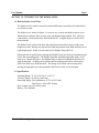
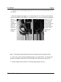
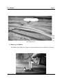
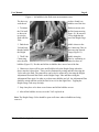
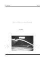
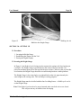
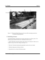
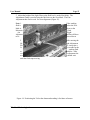
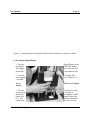
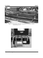
The Hydro-Level
User Manual
Thin Kerf Technologies Inc.
5454-192nd St. Surrey, BC
Canada, V3S 8E5
The Hydro-Level
User Manual
© Thin Kerf Technologies Inc.
5454-192nd St. Surrey, BC
Canada, V3S 8E5
Tel: (604) 576-9455
Toll Free Tel: 1-800-6363-TKT
Fax: (604) 576-8449
Email: [email protected]
Web: www.thinkerf.com
Warranty
TKT provides a two year warranty against defective mechanical and electrical components on the
Hydro-Level as of the purchase date. Shipping costs and custom fees are not included.
The Hydro-Level is a precision instrument. Damage caused by abuse of the user cannot be
covered under warranty.
User Manual
Page i
Table of Contents
Section 1.0
Introducing Your Hydro-Level
1.1
1.2
1.3
1.4
1.5
How the Hydro-Level Works
Specifications
Description - Height Gauge
Description - Vial
Description - Digital Display
2.1
2.2
2.3
Adding Fluid and Removing Air Bubbles
Adding the Fluid
Removing Air Bubbles
Setup Procedure
3.1
3.2
3.3
3.4
Setting Up
Procedure
Locating the Height Gauge
Establishing the Datum
Zeroing the Digital Display
4.1
Taking Measurements
Taking Measurements
5.1
Avoiding Problems and Inaccurate Measurements
Closing the Valves
5.2
Temperature Variance
5.3
Periodic Datum Checks
5.4
The Connecting Tube
5.5
Leap-Frogging
5.6
Collecting Consistent Readings
5.7
Placing the Vial in Awkward Areas
Section 2.0
Section 3.0
Section 4.0
Section 5.0
Thin Kerf Technologies Inc.
Page
No.
1
1
3
4
4
4
6
8
8
8
1
1
1
1
1
3
1
3
1
3
1
3
1
3
1
3
1
3
User Manual
Section 6.0
Page ii
6.1
Troubleshooting
Bubbles Cannot be Removed
6.2
Measurements Are Not Repeatable
6.3
Fluid Movement Is Too Sensitive
7.1
Maintenance and Storage
Maintenance
7.2
Storage
Section 7.0
Thin Kerf Technologies Inc.
1
5
1
5
1
5
1
5
1
5
User Manual
Page 1
SECTION 1.0 - INTRODUCING THE HYDRO-LEVEL
1.1 How the Hydro-Level Works
The Hydro-Level is used to accurately measure differences in machine elevation relative
to a reference point.
The Hydro-Level, shown in Figure 1, is easy to use, accurate and built to operate in an
industrial environment. There are two parts - the Height Gauge and the Vial, which are
connected by a clear flexible tube filled with WD-40. A digital display is used to show
measurements.
The Hydro-Level works on the basis that a fluid in an open tube is always at the same
height at its ends. Raising one tube end will shift the position of the fluid until they are at
equal height again. In this case, the ends are the Height Gauge and Vial.
Measurements are performed by placing the Height Gauge in a fixed spot and moving the
Vial to the measuring points. The Height Gauge has a inclined sight glass with a "zero"
mark on it. Shown in Figure 2, the Height Gauge is adjusted such that the fluid level is
right on this mark. A change in elevation at the measuring point will be reflected by a
shift of the fluid away from this mark. The change in elevation can be measured by
moving the sight glass up or down until the fluid level is at the zero mark again.
1.2 Specifications
Operating Range: 32EF to 120EF [0EC to 40EC]
Accuracy Range: ±0.002 in [±0.05 mm]
Measuring Range: Fine Adjustment - 0.375 in [9.53 mm]
Total Travel - 8.0 in [203.20 mm]
Hose Length: 100.0 ft [30.48 m] max.
Battery: 2 AA Alkaline
Thin Kerf Technologies Inc.
User Manual
Page 2
Height Gauge
Vial
Digital Display
Figure 1. The Hydro-Level.
Zero Mark
Thin Kerf Technologies Inc.
User Manual
Figure 2. Fluid Level
Mark.
1.3 Description Height Gauge
Page 3
Adjusted to the Zero
Slide Rails
Scale
Height Gauge Tube
Height Adjustment
Zero Mark
Fine Adjustment Wheel
Quick Disconnect Fitting
Height Gauge Valve
(Shown opened. Shown
closed in Figure 1).
Inclined Sight Glass
Bull’s-Eye Level
Fig
ure 3. Front View of Height
Gauge.
Adjustment Clamps
Thin Kerf Technologies Inc.
User Manual
Page 4
Levelling Screws
(1 on each corner).
Figure 4. Back View of Height Gauge.
Thin Kerf Technologies Inc.
User Manual
Page 5
1.4 Description - Vial
Valve
(Shown closed).
Cap
Fluid Level
Quick Disconnect
Connecting Tube
(Two 25 ft. tubes provided).
Vial Base
Figure 5. Vial.
1.5 Description - Digital Display
Front Panel Screws
LCD Screen
Inches or Millimetres
Indicator
Cable Connection to Height
Gauge
ON/OFF
Decrease
Mode
Increase
Zero
Figure 6. Digital Display.
SECTION 2.0 - ADDING FLUID AND REMOVING AIR BUBBLES
2.1 Adding the Fluid
Although the Hydro-Level comes fully assembled, a working fluid needs to be added.
This has to be only done once. We recommend the fluid to be WD-40. Any other fluid
can affect measurements or damage the Hydro-Level.
1. Lay out the Connecting Tube.
Thin Kerf Technologies Inc.
User Manual
Page 6
2. Open the valves on the Height Gauge and Vial. The valves are open when their levers
are vertical.
3. Place the Height Gauge higher up (2-3 inches) than the Vial. This forces the fluid into
the lines and minimizes air bubbles. An alternative way is to raise the Height Adjustment
Plate (see
Figure 7). To do
this, loosen
the Adjustment
Clamps.
Next, slide the
Adjustmen
t Plate up along its
slide rails
until the Sight
Glass is a
few inches above
the top of
the Vial. Now,
tighten the
Adjustment
Clamps
again.
Figure 7. Raising the Height Adjustment Plate and Tightening the Adjustment Clamp.
4. Unscrew the Vial Cap and start filling the Hydro-Level with WD-40. To minimize the
amount of air bubbles in the lines, the Vial should not be allowed to be empty of oil.
5. Continue filling the line until the Vial is filled approximately half-way.
Thin Kerf Technologies Inc.
User Manual
Page 7
Figu
re 8.
Filli
ng
the Hydro-Level.
2.2 Removing Air Bubbles
Air bubbles in the fluid's line (Figure 9) cause measurement errors and must be removed.
Air Bubble
Thin Kerf Technologies Inc.
User Manual
Page 8
Figure 9. Air bubbles in the fluid cause measurement errors.
The best way
work the air
we have found is to
bubbles out of the line.
1. To initiate
the Vial until
as shown in
to raise the
fluid will flow
Tube.
fluid movement, raise
the fluid starts moving
Figure 10. Be sure not
Vial so high that the
out of the Height Gage
2. Find the air
Vial and raise
that the bubble
the Height
bubble closest to the
the Connecting Tube so
starts moving towards
Gauge (Figure 11).
3. "Walk" the
bubble along the
Connecting
Tube by continuing to
raise the tube
wherever there are
bubbles (Figure 12). Do this until all the air bubbles have moved out of the line.
4. Chances are, there will be some small bubbles left at the Height Gauge when the
above steps have been done. These can be eliminated by raising and then lowering the
Vial to move the fluid. The same affect can be also be achieved by lowering the Height
Adjustment Plate until the fluid is at the Height Gauge Tube and then raising the
Adjustment Plate again. In order to see how many bubbles are left , the Adjustment Plate
should be raised until the end of the fluid is in view in the Sight Glass. Tapping the
Height Gauge Tube may also help.
5. Step 4 may have to be done several times until all the bubbles are out.
6. After all the bubbles are out, screw the Vial's cap back on.
Note: The Height Gauge Valve should be open at all times when air bubbles are being
removed.
Thin Kerf Technologies Inc.
User Manual
Page 9
Figure 10. Raising the Vial to initiate fluid movement.
Air Bubble
Figure 11.
Connecting Tube
bubble.
Thin Kerf Technologies Inc.
Raising the
at the first air
User Manual
Page 10
Figure 12.
Walking the Air
Bubble to the Height Gauge.
SECTION 3.0 - SETTING UP
3.1 Procedure
1. Locating the Height Gauge.
2. Establishing the datum with the Vial.
3. Zeroing the Digital Display.
3.2 Locating the Height Gauge
In Figure 13, the Hydro-Level is being used to measure the carriage rails for a head-rig in
a sawmill. The Height Gauge is positioned near the center of the area and the Vial
placed at the datum point (to be discussed in the next section). Wherever the user decides
on a location, the Height Gauge should be accessible and placed on a stable platform.
The Height Gauge is also raised up by a wooden block so that it is approximately the
same height as the carriage rails. This will help in zeroing purposes.
The Height Gauge must be levelled with the four Levelling Screws. A Bull's-eye Level is
on the Height Gauge.
Note: If the Hydro-Level needs to be moved around, make sure both valves are closed.
This will prevent any air bubbles from developing.
Thin Kerf Technologies Inc.
User Manual
Vial at Datum Point
Page 11
Carriage
Rails
Placing Height Gauge Near
Center
Figure 13. Placing the Height Gauge near the center of the measuring area and at a
accessible and stable platform.
3.3 Establishing the Datum
As mentioned before, measurements are done with respect to a reference point. The
following steps should be followed to establish this reference point:
1. Find a stable and convenient position on the surface to be measured. In this case, it
would be on top of one of the carriage rails (Figure 14).
2. Place the Vial at the selected point (again make sure the valves are closed).
3. Mark the datum point for future reference.
4. Open both valves to allow for fluid movement.
Thin Kerf Technologies Inc.
User Manual
Page 12
5. Adjust the height of the Sight Glass so the fluid level is at the Zero Mark. The
Adjustment Clamp is used to bring the fluid close to the Zero Mark. The Fine
Adjustment then can be used for exact alignment (Figure 15).
Note: 1.
fluid is
Mark ie.
Measurin
the
Adjustme
to be
If the working
below the Zero
closer to the
g Unit,
Height
nt Plate will have
moved down.
2.
He
Pla
fe
After moving the
ight Adjustment
te, it may take a
w seconds for the
working fluid
stabilize. After
h adjustment the
r should wait
to
eac
use
until the fluid stops moving.
Figure 14. Positioning the Vial at the datum and marking it for future reference.
Thin Kerf Technologies Inc.
User Manual
Page 13
Figure 15. Adjusting the Fine Adjustment Wheel until the fluid level is at the Zero Mark.
3.4 Zeroing the Digital Display
1. Turn the
pressing the
The display
Screen has
Digital Display on by
"ON/OFF" button.
is on when the LCD
some numbers on it.
2. Press the
screen should
“0.00 MM”.
"0" button. The
read “0.000 IN” or
A Few
Display.
Points on the Digital
1. The user
measurement
millimetres.
button will
two. The
which mode
can choose to read
s in inches or
Pressing the “Mode”
toggle between the
display will indicate
the user is in with
Thin Kerf Technologies Inc.
User Manual
Page 14
either an "IN" or a "MM". Measurements are displayed to the closest one-thousandth inch or
one-hundreth millimeter.
2. Turning the display off will not affect the zeroing procedure or the mode the user is in.
It will also redisplay the measurement prior to turning it off. Settings will change
however if the batteries have been changed. The display will also have to be zeroed again
if the cable was accidentally disconnected from either the display or the Height Gauge.
3. Changing the battery is done by removing the Front Panel Screws in the front of the
display. Orient the batteries as shown in the battery compartment and screw the top back
on.
SECTION 4.0 - TAKING MEASUREMENTS
Section 4.1 Taking Measurements
To take measurements:
1. Make sure both valves are closed.
2. Move the Vial to the desired location. For recording purposes it is advisable that
points of measurement be marked off. In Figure 16 we have marked the position of the
Vial and labelled it with a "+10" indicating that it is 10 feet away from the datum point.
2. Open both valves and return to the Height Gauge and wait for the working fluid to
settle. If the fluid has moved in any way then there has been a change in height.
3. Turn the Fine Adjustment Wheel until the fluid level is at the Zero Mark again. The
change in elevation can be read off the Digital Display.
4. Steps 1-3 should be repeated until an elevation profile of the machinery being
measured has been obtained.
Thin Kerf Technologies Inc.
User Manual
Figure 16. Positioning the Vial at the next position to be measured. Note the
reference mark of +10.
Thin Kerf Technologies Inc.
Page 15
User Manual
Page 16
Figure 17. After adjusting the fluid until it is at the Zero Mark again the Digital Display
will indicate the height at the position of the Vial.
SECTION 5.0 AVOIDING PROBLEMS AND INACCURATE MEASUREMENTS
Section 5.1 Closing the Valves
Both valves should be opened only when taking a measurement. Closing the valves when
moving the Hydro-Level will prevent:
1. Accidental spillage.
2. Dirt from getting into the lines.
3. Air bubbles.
Section 5.2 Temperature Variance
The working fluid is susceptible to changes in ambient temperature. If the Hydro-Level is
being used for an extended period, especially when there has been a significant
temperature change, the Hydro-Level should be zeroed again.
Measurements on machines should be done at normal operating temperatures. The
Connecting Tube should be laid out on the machine at least a half hour before the HydroLevel is to be used. This will allow the working fluid enough time to adjust to normal
working temperatures.
Section 5.3 Periodic Datum Checks
The user should make periodic checks to see if the datum point has changed in any way.
Return the Vial to the datum point and check that the Hydro-Level zeroes again.
Section 5.5 The Connecting Tube
When taking measurement over long lengths, it is useful to support the tube - a board
underneath it, for instance. If unsupported, the tube can stretch, which will give
inaccurate measurements.
The tube should be uncoiled before the Hydro-Level is used.
Section 5.6 Leap-Frogging
Thin Kerf Technologies Inc.
User Manual
Page 17
Using the carriage rails as an example, the Hydro-Level will not have enough line to
measure the whole rail. The Height Gauge will have to be moved without changing the
datum.
1. Close the Vial Valve and leave it at the last measuring point. Make sure this elevation
is recorded.
2. Close the Height Gauge Valve and relocate it to its new position.
3. Level the Height Gauge and open both valves.
4. Adjust the fluid until it is at the Zero Mark.
5. Using the “+” and “-“ buttons on the Digital Display, change the readout until it
displays the elevation of the last point. For instance, if the last point was 0.012 inches
then adjust the displays until it reads 0.012 inches.
The Hydro-Level has now been moved with the same datum but with more line to take
measurements.
Section 5.7 Collecting Consistent Readings
When collecting a set of data, the same person should be reading the Zero Mark. This
makes for more consistent readings.
Section 5.8 Placing the Vial in Awkward Areas
Often times it will be difficult to position the Vial. A bed roll is used as an example
(Figure 18). A flat surface is placed on the bed roll so that the Vial can be seated. There
is no problem in doing this as long as the same flat surface is used at the other measuring
points.
Thin Kerf Technologies Inc.
User Manual
Page 18
Figure 18. Using a flat surface to place the Vial in awkward places.
Thin Kerf Technologies Inc.
User Manual
Page 19
SECTION 6.0 TROUBLESHOOTING
Section 6.1 Bubbles Cannot be Removed
• Check for closed valves if the bubbles don't move or are moving slowly . A long
connection tube over 100 ft. will also stop bubble movement.
Section 6.2 Measurements Are Not Repeatable
• Check the lines for bubbles and remove them.
• Temperature changes. Check the datum point periodically.
Section 6.3 Fluid Movement Is Too Sensitive
• The Height Gauge is not levelled. Level the Height Gauge again.
SECTION 7.0 MAINTENANCE AND STORAGE
Section 7.1 Maintenance
• The fluid does not need to be replaced often. The Hydro-Level should be cleaned when
needed to prevent dirt buildup that can cause the Slide Rails to jam.
Section 7.2 Storage
• Ensure valves are closed.
• Release both Quick Disconnects. The Height Gauge and Vial should not leak as they are
both sealed.
• Coil the Connecting Tube to avoid kinks.
• Join the Quick Disconnects.
• Turn off the Digital Display.
Thin Kerf Technologies Inc.