1
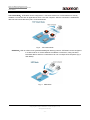
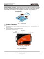
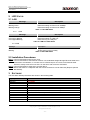
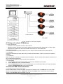
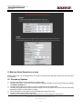
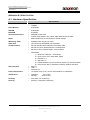
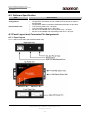
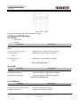
User’s Manual Version 1.2
Devolinx Serial-Ethernet Server
STE-502C
2. LED STATUS
2.1 LAN
Message
Off
Blinking Green
Blinking Orange
2.1.2
Description
Ethernet Disconnected
Data transmitting on Ethernet at 100Mbps
Data transmitting on Ethernet at 10Mbps
Table 1. LAN LED Status
COM
Message
Off
Com1(2)TX Blinking
Com1(2)RX Blinking
Description
No data transmitting on COM port
Data transmitting on COM port
Data receiving on COM port
Table 2. COM Port LED Status
2.1.3 RUN
Message
On
Blinking
Description
Jumper JP1 Pin1 and Pin2 shorted to disable AP firmware
AP firmware running normally
Table 3. RUN LED Status
2.2 Installation Procedures:
Step 1: Connect STE-502C power source Jack.
Step 2: Connect STE-502C to the Ethernet network. Use a standard straight-through Ethernet cable when
connected to a hub/switch, or connect to a PC‘s Ethernet port via a cross-over Ethernet cable.
However, Always make sure ones PC is on the same sub-net as the STE-502C.
Step 3: Connect STE-502C’s serial port to a serial device.
Step 4: Mount STE-502C to a wall/panel with the screws included or to a Din-Rail rack (Require optional
Din-Rail-Kit).
3. SOFTWARE
The STE-502C default parameters are shown in the following table.
Property
IP Address
Gateway
Subnet Mask
User Name
Password
COM 1
COM 2
Link 1
Link 2
SysName of SNMP
SysLocation of SNMP
SysContact of SNMP
Default Value
10.0.50.100
10.0.0.254
255.255.0.0
admin
Null(leave it blank)
9600,None, 8, 1, No flow control, buffer disabled, packet delimiter timer 2ms
9600,None, 8, 1, No flow control, buffer disabled, packet delimiter timer 2ms
Type: TCP Server, Listen port 4660, Filter=0.0.0.0, Virtual COM disabled
Type: TCP Server, Listen port 4661, Filter=0.0.0.0, Virtual COM disabled
name
location
contact
Copyright © 2007 Aaxeon Technologies, LLC
All rights reserved.
- 10 -