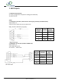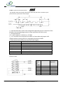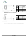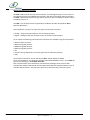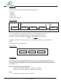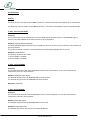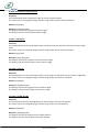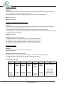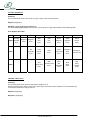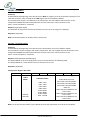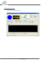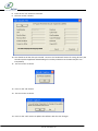
1
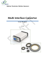
Netzer Precision Motion Sensors Multi Interface Convertor User Manual 1/1/2009 Notice This guide is delivered subject to the following conditions and restrictions: This guide contains proprietary information belonging to Netzer Precision Motion Sensors Ltd. Such information is supplied solely for the purpose of assisting users of the MIC installation and integration. Information in this document is subject to change without notice. Document No. MIC‐UM Copyright ©2007 Netzer Precision Motion sensors LTD. All rights reserved. CNV‐00001‐01 MIC Catalog Number: Cable Kit Catalog Number (USB included) CB‐01056‐00 USB cables ‐ USB A to USB Mini B cable) Related Document Revision History: Ver. 0.1 Jan 2008 (MIC‐UM) Initial Release Ver. 0.2 Apr 2008 (MIC‐UM) NCP‐Document Revision 3.4 Ver .0.4 Aug 2008 (drawings updates) Ver. 1.01 Jan 2009 (Release) Ver. 1.02 Mar 2009 (SSI pin out update) Netzer Precision Motion Sensors LTD Misgav Industrial Park P.O.Box 1359 , DN Misgav Israel 20179 Phone +972 4 999 0420 Fax +972 4 999 0432 www.netzerprecision.com MIC-01 ,User Manual, 2 Introduction This user manual describes the MIC multi interface converter and the steps for its wiring, installation and integration. Following these guidelines ensures maximum functionality of the converter and the system to which it is connected. 1.1 Product Description The MIC is a multi interface converter that operates with Netzer precision motion sensors products and provides immediate and flexible interface to variety of industrial control systems. The product is for DEMO purposes only – (testing, development and demonstration) – for full operational integration please consult our engineering support. 1.2 Product Features 1.2.1 Signal converter and Post processing. Provides signal conversion of the Electric Encoder ™ Sine/Cosine to absolute position SSI, incremental AqB and set up via USB and RS‐232. 1.2.2 Setup Testing, setup and configuration of the position sensor and MIC via USB interface. 1.2.3 Installation Assistance tool for proper installation via USB interface. 1.2.4 Demonstration & Training. 1.3 Communication Options The MIC provides USB interface as a primary interface for setup/configuration & testing. RS‐ 232 available as secondary channel of the positing data for higher level controllers. Primary positions (mechanical) are available on SSI, AqB and RS‐422. 1.4 Position feedback options 1.4.1 Input 1.4.1.1 Netzer native Sine/Cosine (analog) . 1.4.2 Output 1.4.2.2 AqB + index, SSI , RS‐232 , RS‐485, RS‐422 , USB. 1.5 System Architecture MIC-01 ,User Manual, 3 1.6 How to Use this Guide In order to install and operate your MIC unit, you will use this manual in conjunction with a set of Netzer documentation. ‐ Data sheet and installation guide of the relevant encoder. ‐ Installation is your first step; cables + Software (USB drivers + Encoder Explorer) on your PC. ‐ Communicating with the position sensor is your second step for set up/configuration or tests. There are several relevant documents which you might use if needed. ‐ Position sensor installation guide – according to the sensor model. Chapter 2: Installation 2.1 Hardware requirements 1. MIC 2. USB cable, Mini – B to A 3. PC / MS – Win XP 2.2 Software 1. USB drivers 2. Encoder Explorer 2.3 Cables Configuration 2.3.1 USB – please use standard mini – B USB interface cable (Supplied, CAT No. : CB‐01‐56‐00) MIC-01 ,User Manual, 4 3. MIC Outputs 3.1 RS‐232 communication For setup, configuration and position reading (low bandwidth) 19,200 by default Cable: 3.1.1 RS‐232 to controller, with external 5 VDC supply (can be by the USB interface) MIC interface: J2 Cable connector: DB15 HD Female, DB9 Female Cable Power DB15 HD Function supply Female (optional) 1 5 VDC 5 VDC 2 RS‐232 RX 3 RS‐232 TX 15 GND GND 3.1.2 RS‐232 – PC com port (CAT No: CB‐00001‐01) MIC interface: J2 Cable: DB15 HD Female. PC interface ‐ DB9 Female PC COM Cable DB15 HD Function DB9 Female Female 5 VDC 1 (optional) MIC-01 ,User Manual, 5 2 RS‐232 RX 3 3 RS‐232 TX 2 15 GND5 VDC 5 3.2 SSI ‐ Synchronous Serial Interface The absolute mechanical angle information derived by the electric encoder is post processed into synchronous serial output n = total # of data bits, 24 bits. Not configurable (depending on the resolution of the Encoder, the corresponding amount of most significant bits will be zero). T = clock period (sec) 1/T = clock frequency ~100 kHz to ~2.5 MHz. t1 = T/2 ,minimum time required for encoder to freeze data and prepare shift registers before receiving the first rising edge to prompt the MSB t2 = data transmission delay (increases with cable length) Output code Natural binary Resolution By encoder model Serial output SSI Differential data output to RS‐422 Clock SSI Differential data input to RS‐422 Config mode Diff data input / output to 422 with NCP Voltage +5V Clock frequency ~100 kHz to ~2.5 MHz Monoflop time 25 usec t3 = monoloop time , required delay to refresh position data between subsequent position reads. MIC Function DB15 HD Female 1 5 VDC 4 SSI CLK + 5 SSI CLK ‐ 7 SSI DATA + 6 SSI DATA ‐ 15 GND MIC-01 ,User Manual, 6 Power supply (optional) 5 VDC GND 3.3 RS‐422 MIC Function Power supply DB15 (optional) HD Female 1 5 VDC 5 VDC 4 RS 422 RX + 5 RS 422 RX ‐ 6 RS 422 TX ‐ 7 RS 422 TX + 15 GND GND The dashed line between pin 14 and 5 connects an internal 120 Ohm termination resistor. It must be connected if the MIC is the last device on the bus. 3.4 RS‐485 MIC Function Power supply DB15 (optional) HD Female. 1 5 VDC 5 VDC 4 RS 485 + 5 RS 485 ‐ 15 GND GND The dashed line between pin 14 and 5 connects an internal 120 Ohm termination resistor. It must be connected if the MIC is the last device on the bus. MIC-01 ,User Manual, 7 3.5 AqB + Index Incremental (non absolute) AqB + single index Output code Incremental AqB + index Resolution By encoder model Signal shape Square Output frequency Max ….. Incremental output RS‐ 422 Voltage +5V MIC DB15 HD Female 1 8 9 10 11 12 13 15 MIC-01 ,User Manual, 8 Function Power supply (optional) 5 VDC A A B B I I GND 5 VDC GND 3.6 DS sensor type (analog Sin / Cosine) (CAT No: CB‐00003‐01) MIC interface – J1 DB15 HD Male Sensor interface – DF13‐6P DS Sensor MIC Function Color DF13‐6P DB15 HD Male 1 GND Black 9 2 C/F Gray 2 3 SIN Blue 7 4 Vr Green 8 5 COS Yellow 15 6 5V Red 1 3.7 RE sensor type (Digital AqBiSS) (CAT No: for RE‐37, CB‐00002‐01 , for RE‐57, CB‐00002‐ 02 ) MIC interface – J1, DB15 HD Male Sensor interface – DF13‐12P DF13‐ 12P ‐ RE 1 2 3 4 5 6 7 8 9 10 11 12 Function Vcc GND A A B B I I MA MA SL SL MIC-01 ,User Manual, 9 DB15 HD Male ‐ MIC 1 9 2 10 3 11 4 12 5 13 6 14 USB MIC MIC-01 ,User Manual, 10 Netzer Communication Protocol The NCP is bidirectional Serial protocol interface. It was designed to get an easy access to the absolute position and additional parameters and data of the Netzer Electric Encoders. The NCP is Master Slave protocol type, which means no data is available on the bus unless the Master asks for it. The NCP is one of the protocols supported by the Netzer Encoder Interpolator (Multi Interface Converter). The Interpolator can get as an input two types of the Netzer Encoders: • Analog – Sin/Cos Encoder known as the DS family Encoders. • Digital – AqBiSS or BiSS only Encoder known as the RE² family Encoders. As an output the following communication interfaces are available using the interpolator: • RS232 as ASCII terminal. • RS232 using NCP protocol. • RS485 using NCP protocol. • RS422 using NCP protocol. • SSI. • Virtual homing (AqB with pre counter generator for absolute position). • USB. Three types of interfaces can be used by the NCP – RS232, RS422 or RS485. Up to 32 Interpolators can share the same Bus when RS422/RS485 is used – in the NCP this type of bus topology is called Multi Slave Bus. Each communication from the Master (Controller/PC/TE) begins with the slave MIC (Interpolator) address followed by the desirable command and completed with an easy to calculate XOR checksum. The end of the protocol is detected using a timeout control. MIC-01 ,User Manual, 11 Data Format: The data on the Serial interface has the following basic format: • 1 start bit. • 8 data bits. • 1 stop bit. • Parity: none. • Programmable baud rate. Protocol Timing: TS Address TL Command Data * CheckSum Address Figure 1 TS ‐ Pause time between individual data packets. It must be smaller than Timeout. TL ‐ Bus dead time to next address detection. It must be greater than Timeout. Checksum – EXOR link of the bytes transmitted, including address and command. 50 TimeOut ≅ BudeRate The NCP is controlled via a timeout protocol. The first byte after a Timeout is interpreted as an address. * Optional, depend on the command. Error Response: Address 0xEE Figure 2 Checksum Error Handling: Commands which cannot be processed (due to protocol errors, wrong command arguments or internal Encoder errors) leads to the command processing being cancelled and to respond with an error response as described above. The Error type can read out using a special command as will be described later on. After Error response Use the following steps: 1. Read the error code by using 0x3F – "Read Error" command. 2. Clear the error flag by using 0x40 – "Reset Error" command. Notes: 1. Reading the error won't clear the error flag. MIC-01 ,User Manual, 12 2. Reading the error code is optional operation, but, you always have to clear the Error flag, if not, you will keep getting the error response. Command Set: The command set, available for each Encoder, may vary. MIC-01 ,User Manual, 13 Overview of the commands: Command Function Terminal Equipment Request Interpolator Response 0x2F 0x30 0x31 0x32 0x33 0x34 0x35 0x36 0x37 0x38 0x39 0x3A 0X3B 0X3C 0X3D Enter Service Mode Write EEPROM(5) Read EEPPROM(5) Write Register(5) Read Register(5) Change to Coarse Change to Fine Read Electric Angle Position Get Coarse Get Fine Do NM Get Ni Do NM Get Absolute Position Start Trace Stop Trace Get Absolute Position from Trace (A)(2F)(P3)(P2)(P1)(P0)(CS) (A)(30)(EE‐A)(EE‐D)(CS) (A)(31)(EE‐A)(CS) (A)(32)(REG‐A)(REG‐D)(CS) (A)(33)(REG‐A)(CS) (A)(34)(CS) (A)(35)(CS) (A)(36)(CS) (A)(37)(CS) (A)(38)(CS) (A)(39)(CS) (A)(3A)(CS) (A)(3B)(CS) (A)(3C)(CS) (A)(3D)(CS) 0X3E Get Status (A)(3E)(CS) 0X3F Read Error (A)(3F)(CS) 0X40 0X41 0x42 Reset Error Set Address Set Configuration (A)(40)(CS) (A)(41)(DEV‐A)(CS) (A)(42)(CONFIG‐H)(CONFIG)(CS) 0x43 Read Configuration (A)(43)(CS) 0x44 0x45 0x46 0x47 0x48 0x49 Reset Interpolator Initialize Read Absolute Position Read Absolute Position Calibration(2)(5) Re Initialize Encoder Get Version (A)(44)(CS) (A)(45)(CS) (A)(46)(CS) ‐ (A)(48)(CS) (A)(49)(CS) (A)(2F)(S)(CS) (A)(30)(CS) (A)(31)(EE‐D)(CS) (A)(32)(CS) (A)(33)(REG‐D)(CS) (A)(34)(CS) (A)(35)(CS) (A)(36)(H)(L)(CS) (A)(37)(H)(L)(CS) (A)(38)(H)(L)(CS) (A)(39)(H)(L)(CS) (A)(3A)(HH)(HL)(LH)(LL)(CS) (A)(3B)(CS) (A)(3C)(CS) (A)(3D)(HH)(HL)(LH)(LL)(CS) (A)(3E)(STATUS‐ H)(STATUS)(CS) (A)(3F)(ERR2)(ERR1)(ERR0)( CS) (A)(40)(CS) (A)(41)(CS) (A)(42)(CS) (A)(43)(CONFIG‐ H)(CONFIG)(CS) (A)(44)(CS)(4) (A)(45)(CS) (A)(46)(HH)(HL)(LH)(LL)(CS) ‐ (A)(48)(CS) (A)(49)(VER)(S‐ MIC-01 User Manual 14 Maximum Response Time (1) 380us 4ms 4ms 10ms 10ms 400ms 400ms 600us 400ms 400ms 800ms 800ms 300us(3) 300us 350us 600us 6000us 300us 4ms 8ms 4ms 350us(3) 900ms 350us ‐ 1100ms 2ms VER)(D)(M)(Y)(CS) (A)(4A)(CS) ‐ (A)(4C)(HH)(HL)(LH)(LL)(CS) (A)(4D)(CS) 0x4A Go To Bootloader(5)(2) (A)(4A)(CS) 8ms 0x4B Motion(2)(5)(7) ‐ ‐ 0x4C Get Encoder Parameters(6) (A)(4C)(P)(CS) 8ms 0x4D Set UZP(6) (A)(4D)(HH)(HL)(LH)(LL)(CS) 10ms Table 1 (1) The response times given do not include transmission times and protocol timeout (Ts & TL) which depend on the baud rate. Note that if the TE is a PC with non Real time operation system on it additional delay is added by the OS. (2) For Netzer internal use. (3) After execution of those commands, additional time delay of 2 sec is required before any another command can be execute. (4) The response from the Interpolator is available only from firmware version 5.109, in older versions no response is available to this command. (5) The Interpolator must be in "Service Mode" to execute those commands. (6) Available from firmware version 5.109. (7) Available from firmware version 5.100. (8) Will become available from firmware version 5.300. MIC-01 User Manual 15 The Commands General The field (A) is the first field in all the NCP commands – this field represents the address of the Interpolator. The field (CS) is the last field in all the NCP commands – this field is the Checksum of the transmitted fields. 1. 0x2F ‐ Enter Service Mode: Summary: This command will set the Interpolator to Service Mode which will allow access to the EEPROM,registry memory and other additional sensitive functions of the Interpolator. Request: (A)(2F)(P3)(P2)(P1)(P0)(CS) The fields (P3)(P2)(P1)(P0) represent the password you must set to execute the command, contact Netzer to get the password. To exit Service Mode execute the command while the fields (P3)(P2)(P1)(P0) are set to zero. Response: (A)(2F)(S)(CS) The field (S) represents the status: 1‐ Service Mode is enabled. 0‐ Service Mode is disabled. 2. 0x30 ‐ Write EEPROM: Summary: This command will write the internal EEPROM memory of the Interpolator, to use this command the Interpolator must be in Service Mode. Request: (A)(30)(EE‐A)(EE‐D)(CS) The field (EE‐A) represents the EEPROM address to be written. The field (EE‐D) represents the EEPROM Data to be written. Response: (A)(30)(CS) 3. 0x31 ‐ Read EEPROM: Summary: This command will Read the internal EEPROM memory of the Interpolator, to use this command the Interpolator must be in Service Mode. Request: (A)(31)(EE‐A)(CS) The field (EE‐A) represents the EEPROM address to be read. Response: (A)(31)(EE‐D)(CS) The field (EE‐D) contains the data in the requested address. MIC-01 User Manual 16 4. 0x32 ‐ Write Register: Summary: This command will write the internal Register memory of the Interpolator, to use this command the Interpolator must be in Service Mode. Request: (A)(32)(REG‐A)(REG‐D)(CS) The field (REG ‐A) represents the Register address to be written. The field (REG ‐D) represents the Register Data to be written. Response: (A)(32)(CS) 5. 0x33 ‐ Read Register: Summary: This command will Read the internal Register memory of the Interpolator, to use this command the Interpolator must be in Service Mode. Request: (A)(33)(REG ‐A)(CS) The field (REG ‐A) represents the Register address to be read. Response: (A)(33)(REG ‐D)(CS) The field (REG ‐D) contains the data in the requested address. 6. 0x34 ‐ Change to Coarse: Summary: This command will set the connected Encoder to Coarse mode. To read the electric angle of the Coarse channel after execution of this command, use 0x36: "Read Electric Angle Position" command. Request: (A)(34)(CS) Response: (A)(34)(CS) 7. 0x35 ‐ Change to Fine: Summary: This command will set the connected Encoder to Fine mode. To read the electric angle of the Fine channel after execution of this command, use 0x36: "Read Electric Angle Position" command. Request: (A)(35)(CS) Response: (A)(35)(CS) MIC-01 User Manual 17 8. 0x36 ‐ Read Electric Angle Position: Summary: This command will return the electric angle of current channel position. The return value is an unsigned integer with the range of the current channel resolution. Request: (A)(36)(CS) Response: (A)(36)(H)(L)(CS) The field (H) contains the high byte of electric angle. The field (L) contains the low byte of electric angle. 9. 0x37 – Get Coarse: Summary: This command will set the connected Encoder to Coarse mode and will return the Coarse electric angle value. The return value is an unsigned integer with the range of the Coarse channel resolution. Request: (A)(37)(CS) Response: (A)(37)(H)(L)(CS) The field (H) contains the high byte of Coarse electric angle. The field (L) contains the low byte of Coarse electric angle. 10. 0x38 – Get Fine: Summary: This command will set the connected Encoder to Fine mode and will return the Fine electric angle value. The return value is an unsigned integer with the range of the Fine channel resolution. Request: (A)(38)(CS) Response: (A)(38)(H)(L)(CS) The field (H) contains the high byte of Fine electric angle. The field (L) contains the low byte of Fine electric angle. 11. 0x39 – Do NM Get Ni: Summary: This command will perform the NM algorithm and will return the Fine pole position. The return value is an unsigned integer with the range of the Fine channel poles. Request: (A)(39)(CS) Response: (A)(39)(H)(L)(CS) The field (H) contains the high byte of Fine pole position. The field (L) contains the low byte of Fine pole position. MIC-01 User Manual 18 12. 0x3A – Do NM Get Absolute Position: Summary: This command will perform the NM algorithm and will return the absolute position of the Encoder. The return value is an unsigned long (four bytes) with the range of the total Encoder resolution (Fine poles multiply by the Fine resolution). Request: (A)(3A)(CS) Response: (A)(3A)(HH)(HL)(LH)(LL)(CS) The field (HH) contains the absolute position ‐ high byte of the high word. The field (HL) contains the absolute position ‐ low byte of the high word. The field (LH) contains the absolute position ‐ high byte of the low word. The field (LL) contains the absolute position ‐ low byte of the low word. Note: to get the absolute position in degrees for rotary Encoder uses the following expression: AbsolutePosition( Degrees) = 360o ⋅ AbsolutePosition(Count ) FineP ⋅ FineR 13. 0x3B – Start Trace: Summary: This command is one of three commands (0x3B, 0x3C and 0x3D) that are responsible to get the absolute position from the Encoder with minimum time delay. This command will perform the NM algorithm to find the absolute position, and then an internal software algorithm will keep reading the Fine channel to trace the changes and to update the absolute position. This method uses only the BiSS signals from the Encoder, so in digital Encoder (RE² family) it is possible to use only six lines (two lines for supply and four lines for the BiSS). Request: (A)(3B)(CS) Response: (A)(3B)(CS) Notes: 1. After execution of this command you must wait additional 2 seconds before using other commands. 2. After execution of this command, you can use only the 0x3C or 0x3D commands. To use another commands you must first exit the Trace mode by using the 0x3C command. 3. Since this method is a software algorithm, it is limited by the sample rate of the Fine channel read – therefore high Encoder speeds are not supported under this method (see commands 0x45 and 0x46 as alternatives). For more information regarding this method refer to AN‐102 Page 17. MIC-01 User Manual 19 14. 0x3C – Stop Trace: Summary: This command is one of three commands (0x3B, 0x3C and 0x3D) that responsible to get the absolute position from the Encoder with minimum time delay. This command will stop the Trace mode as described in section 13 ‐ 0x3B command. Request: (A)(3C)(CS) Response: (A)(3C)(CS) 15. 0x3D – Get Absolute Position from Trace: Summary: This command is one of three commands (0x3B, 0x3C and 0x3D) that responsible to get the absolute position from the Encoder with minimum time delay. This command will return the absolute position of the Encoder using the Trace method. The return value is an unsigned long (four bytes) with the range of the total Encoder resolution (Fine poles multiplied by the Fine resolution). Request: (A)(3D)(CS) Response: (A)(3D)(HH)(HL)(LH)(LL)(CS) The field (HH) contains the absolute position ‐ high byte of the high word. The field (HL) contains the absolute position ‐ low byte of the high word. The field (LH) contains the absolute position ‐ high byte of the low word. The field (LL) contains the absolute position ‐ low byte of the low word. 16. 0x3E – Get Status: Summary: This command will return the Status of the Interpolator. Request: (A)(3E)(CS) Response: (A)(3E)(STATUS‐H)(STATUS)(CS) The field (STATUS) contains Status of the Interpolator as described in the following table. The field (STATUS‐H) is reserved for future use and will read out as zero. Status Register bits table: 7 6 5 4 3 2 1 0 Error Trace By Encoder Interface: Encoder Service Reference Encoder Flag: Fine Encoder: Mode: Mode: Type: Mode: 0x00: AqBiSS 0x01: Analog 0: No 0x02: BiSS Only 0: Fine 0:Disable 0:Disable 0:Rotary 0: Disable Error 0x03: No Encoder 1: Coarse 1:Enable 1:Enable 1:Linear 1: Enable 1: Error Table 2 MIC-01 User Manual 20 17. 0x3F – Read Error: Summary: This command will return the last Error type, if exist, from the Interpolator. Request: (A)(3F)(CS) Response: (A)(3F)(ERR2)(ERR1)(ERR0)(CS) The fields (ERR2)(ERR1)(ERR0) contain a bit map of the Error type as described in the following table Error Register bits table: 7 6 Analog Register ERR0 Encoder Error Error ERR1 ERR2 5 4 3 2 1 0 Register Error Wait Start Error Wait Ack Error Write Register Error Read Register Error Read Sensor Error No Encoder Error Trace Mode Error NM Error NCP NCP Unauthorized Check Sum Error Error Read Change to Change to Parameter Fine Coarse Error Error Error NCP Not Available Error NCP Busy Error NCP Data Length Error Table 3 18. 0x40 – Reset Error: Summary: This command will clear the Error flag (Status register bit 7). When the Interpolator detect an Error the Error flag is set and the Error Response is transmitted every command until the Error flag is cleared. Request: (A)(40)(CS) Response: (A)(40)(CS) MIC-01 User Manual 21 19. 0x41 – Set Address: Summary: As described at the beginning of this document the NCP can support up to 32 Interpolators (Slaves) on the same bus, therefor, every message of the NCP begins with an Interpolator address. This command will assign a new address to the Interpolator. The new address will be written to the Interpolator EEPROM and will became effective the next power up or after execution of the 0x44 – "Reset Interpolator" command. Request: (A)(41)(DEV‐A)(CS) The field (DEV‐A) represents the new Slave address and can be in the range of 1~253(Dec). Response: (A)(41)(CS) Note: The default address is 20 (Dec) which is 0x14 (Hex). 20. 0x42 – Set Configuration: Summary: As described at the beginning of this document the Interpolator can work in different modes. This command is used to configure the modes of operation. The new configuration will be written to the Interpolator EEPROM and will became effective the next power up or after execution of the 0x44 – "Reset Interpolator" command. Request: (A)(42)(CONFIG‐H)(CONFIG)(CS) The field (CONFIG) is the new configuration to be set as described in the following table. The field (CONFIG‐H) is reserved for future use and must set to zero. Response: (A)(42)(CS) Configuration Register bits table: 7 6 Index Mode: 0x00:EA 0x01:MA 5 4 3 UART Baud Rate: 0x00: 1200 0x01: 2400 0x02: 4800 0x03: 9600 0x04: 19200 0x05: 38400 0x06: 57600 0x07: 115200 2 1 0 Communication Type: 0x00: RS232 Terminal 0x01: NCP Command RS232 0x02: NCP Command RS422 0x03: NCP Command RS485 0x04: SSi 0x05: HomeLess (400msec Pre Start Timer) 0x06: HomeLess (600msec Pre Start Timer) 0x07: HomeLess (800msec Pre Start Timer) Table 4 Note: To set the Communication Type to RS232 Terminal the Interpolator must be in Service Mode. MIC-01 User Manual 22 21. 0x43 – Read Configuration: Summary: This command will return the current configuration. Request: (A)(43)(CS) Response: (A)(43)(CONFIG‐H)(CONFIG)(CS) The field (CONFIG) represents the current configuration as described in the above table. The field (CONFIG‐H) is reserved for future use and will read out as zero. 22. 0x44 – Reset Interpolator: Summary: This command will reset the Interpolator. Request: (A)(44)(CS) Response: (A)(44)(CS) The response from the Interpolator to this command is available only from firmware version 5.109, in older versions no response is available to this command. Note: After execution of this command you must wait additional 2 seconds before using other commands. 23. 0x45 – Initialize Read Absolute Position: Summary: This command is one of two commands (0x45 and 0x46) that are used to get the absolute position from the Encoder with minimum time delay. This command will perform the NM algorithm to find the absolute position, and then a hardware circuit will keep reading the Fine channel and will update the changes to the absolute position. Contrary to Trace commands (0x3B, 0x3C and 0x3D) this method uses all the AqBiSS signals from the Encoder so in digital Encoder (RE² family) all the lines from the Encoder must be connected to the Interpolator. In addition this method does not limit the Encoder speed therefore, high Encoder speeds are supported. Request: (A)(45)(CS) Response: (A)(45)(CS) Note: If one of the commands that have a direct effect on the encoder is executed (like Change to Coarse – 0x34), you must execute this command again before using the 0x46 command. MIC-01 User Manual 23 24. 0x46 – Read Absolute Position: Summary: This command is one of two commands (0x45 and 0x46) that are used to get the absolute position from the Encoder with minimum time delay. This command will return the absolute position of the Encoder. The return value is an unsigned long (four bytes) with the range of the total Encoder resolution (Fine poles multiply by the Fine resolution). Request: (A)(46)(CS) Response: (A)(46)(HH)(HL)(LH)(LL)(CS) The field (HH) contains the absolute position ‐ high byte of the high word. The field (HL) contains the absolute position ‐ low byte of the high word. The field (LH) contains the absolute position ‐ high byte of the low word. The field (LL) contains the absolute position ‐ low byte of the low word. 25. 0x47 – Calibration: Summary: This command belongs to a group of sub commands that are used to calibrate the Encoder. Note: For Netzer internal use only. 26. 0x48 – Re Initialize Encoder: Summary: This command will first check the connected Encoder interface (Analog/BiSS Only/AqBiSS or No Encoder), then it will read the Encoder parameters, and then it will perform the NM algorithm. This command is very useful if you change (or disconnect) the Encoder when the Interpolator is powered‐on, in fact this command is executed automatically on every power‐on or reset. Request: (A)(48)(CS) Response: (A)(48)(CS) 27. 0x49 – Get Version: Summary: This command will return the firmware version and the release date. Request: (A)(49)(CS) Response: (A)(49)(VER)(S‐VER)(D)(M)(Y)(CS) The field (VER) contains the firmware version. The field (S‐VER) contains the firmware sub version. The field (D) contains the firmware release day. The field (M) contains the firmware release month. MIC-01 User Manual 24 The field (Y) contains the firmware release year (when Y=0 the year is 2000 and when Y=255 the year is 2255 and). 28. 0x4A – Go To Bootloader: Summary: This command will set the Interpolator to Bootloader mode. This command is used by the Netzer Firmware Loader Program. You must re‐power or restart the Interpolator for this command to become effective. To execute this command the Interpolator must be in Service Mode (see command 0x2F). Request: (A)(4A)(CS) Response: (A)(4A)(CS) Note: For Netzer internal use only. 29. 0x4B – Motion: Summary: This command belongs to a group of sub commands that are used to operate the Motion module of the Interpolator (the Interpolator contains a lean Motion Controller). By connecting a motor you can close a motion loop with the connected Encoder. Note: For Netzer internal use only. 30. 0x4C – Get Encoder Parameters: Summary: This command will return the desired Parameter of the connected Encoder. The return value is an unsigned long. Request: (A)(4C)(P)(CS) The field (P) represents the desired Parameter to be read as described in the following table. Desired Parameter Number Parameter Symbol (P) 0 N 1 M 2 CAA 3 AZP 4 UZP 5 FMPL 6 FLBI 7 Fine Resolution 8 Coarse Resolution Table 5 MIC-01 User Manual 25 Response: (A)(4C)(HH)(HL)(LH)(LL)(CS) The field (HH) contains the parameter value ‐ high byte of the high word. The field (HL) contains the parameter value ‐ low byte of the high word. The field (LH) contains the parameter value ‐ high byte of the low word. The field (LL) contains the parameter value ‐ low byte of the low word. Note: This command is available only from firmware version 5.109 For more information regarding the Parameter Symbols refer to UG‐206 Pages 35~37. 31. 0x4D – Set UZP: Summary: This command will set the UZP parameter (User Zero Position). The return value is an unsigned long. Request: (A)(4D)(HH)(HL)(LH)(LL)(CS) The field (HH) is the UZP to set ‐ high byte of the high word. The field (HL) is the UZP to set ‐ low byte of the high word. The field (LH) is the UZP to set ‐ high byte of the low word. The field (LL) is the UZP to set ‐ low byte of the low word. Response: (A)(4D)(CS) Note: This command is available only from firmware version 5.109 more information regarding For the UZP Parameter refer to UG‐206 Page 37 MIC-01 User Manual 26 Netzer Encoder Explorer The encoder explorer provides immediate access to the Encoder parameters via the MIC for Configuration, Testing and Demonstration purposes. Encoders which are members of the DS / DR product line (analog feedback) are not holding any parameters in "memory" of the encoder!! – Therefore – the MIC should be updated with the characteristic of each encoder prior to operate it manually of by uploading external parameters file. Step 1: Installation Instructions 1. Insert the disk labeled "Encoder Explorer" in to the CD‐ROM drive drive. 2. The welcome screen is shown below: 3. For installation the USB Driver Click on the "USB Driver Installation" button and follow the instructions – must be done for the first time. 4. For installation the Encoder Explorer Software Click on the "Encoder Explorer Installation" button and follow the instructions. MIC-01 User Manual 27 Step 2: operation Instructions 1. Double‐click the "Encoder Explorer" icon. MIC-01 User Manual 28 Step 3: operation Instructions – creation of a new data file Use this option when you have to create NEW encoder data file from scratch and download / save by the end. 1. For updating the DS (encoder) model and other encoder parameters …"File ‐> New". 2. Choose the encoder type from the list. 3. Enter his serial number (9 digits). 4. Enter the next parameters if you know them: a. CAA b. Offsets – Sin and Cos of Fine channel c. Offsets – Sin and Cos of Coarse channel 5. Press on the "Encoder File Folder" button for choosing the directory to save the data. 6. Press on the "Finish" button to finish and quit. 7. The next screen is shown: MIC-01 User Manual 29 8. Press on the "Yes" button to continue. 9. The next screen is shown: 10. You should see all the data you entered. Press on the "Download" button for saving all data. (the encoder explorer application downloading the encoder parameters to the MIC interface unit ‐ interpolator) 11. The next screen is shown: 12. Press on the "OK" button. 13. The next screen is shown: 14. Press on the "YES" button to update the software with the new changes. MIC-01 User Manual 30 Step 4: operation Instructions – Loading a new data file 1. Use… "File ‐> Load". 2. Press the "File" button and choose the date file of the Encoder. 3. Press on the "Download" button for loading all data. 4. The next screen is shown: 5. Press on the "OK" button. 6. The next screen is shown: 7. Press on the "YES" button to update the software with the new changes. MIC-01 User Manual 31 MIC firmware update guide: The firmware of the MIC can be updated using the Netzer Firmware Loader. To run it, follow the following instructions: 1. Go to start menu, then All Programs, then Netzer, then Firmware Loader and then chose Firmware Loader from the menu. A window will appear asking for a password: 2. Enter the following password: 141176. 3. The next screen is shown: 4. Now press the Enter Boot Mode button (the red LED on the front side of the MIC will start blinking faster). 5. The next screen is shown: MIC-01 User Manual 32 6. Press the Open File button. 7. The next screen is shown: 8. Choose a file that corresponds to the version you wish to update to and press the Open button. 9. The next screen is shown: MIC-01 User Manual 33 10. Now press the Program Memory button. A progress bar will appear, wait until it reaches the end. 11. The next screen is shown: 12. Now press the Data Memory button. A progress bar will appear, wait until it reaches the end. 13. The next screen is shown: 14. Now press the Exit Boot Mode button. 15. The next screen is shown: MIC-01 User Manual 34 16. And that is it. The MIC Firmware is now updated to the desired version. The program can be closed now. Note: steps 12 and 13 can be skipped if MIC’s parameters need not to be changed during firmware version update. Otherwise, the MIC will be having all the parameters set to default. Reset guide: The reset is active only when the MIC is configured to be in the Virtual Homing mode. In order to reset the MIC you must drive the RESET pin to low. The RESET low time must be more then 50 ms and less then 150 ms. Code Example The following section contains a number of simple C code examples on how to implement the NCP. Note that those code examples are meant to get a concept of implementation, if you wish to use those examples on a PC it will be better that they run as independent thread or if you wish to use those examples on an uC/DSP/DSC it will be better to change the implementation to a State Machine structure. MIC-01 User Manual 35 MIC-01 User Manual 36 MIC-01 User Manual 37 MIC-01 User Manual 38