1
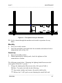
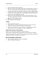
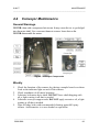
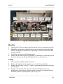
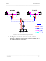
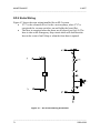
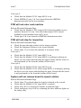
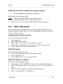
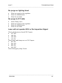
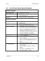
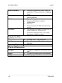
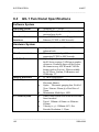
MAINTENANCE
© MVT
____________________________________________________________________________
Chapter
Maintenance
4
4.0
Maintenance
Chapter Contents
4.1
Introduction ..................................................................... 58
4.2
Electrical Maintenance ................................................... 58
4.3
X-Y Table Maintenance .................................................. 63
4.4
Conveyor Maintenance ................................................... 66
4.5
Pneumatic Maintenance.................................................. 67
4.6 SP-2 Additions ................................................................... 69
4.7 General Maintenance ......................................................... 73
Appendix I - Requirements Listing .......................................... 73
Appendix II - Maintenance Checklists ..................................... 74
Summary
This chapter describes a maintenance schedule for the inspection
system. Where possible it refers to the electrical schematic drawing
numbers that describe the circuits involved. They are contained in a
____________________________________________________________________________
57
5000-0088
© MVT
MAINTENANCE
____________________________________________________________________________
separate document. This schedule must be strictly adhered to and be
performed only by qualified personnel.
4.1
Introduction
Maintenance is divided into weekly, monthly, quarterly and yearly schedules. It
is also divided into five main sections, each covering an area on the machine.
These areas are as follows;
• Electrical Maintenance.
•
X-Y table Maintenance.
•
Conveyor Maintenance.
•
Pneumatic Maintenance.
•
General Maintenance.
WARNING
Maintenance must only be carried out by trained personnel.
4.2
Electrical Maintenance
Weekly
1.
2.
3.
4.
Visually inspect the electrical control panel by turning off the machine
at the ON/OFF switch and putting the isolator handle in the OFF
position. Open the back door. Make sure the computer has been
shutdown correctly before this is done.
Inspect all electrical equipment on the machine for damaged contacts,
exposed wire cores and frayed insulation.
Ensure there are no items in front of the transformer panel; i.e. Check
that the vent is kept clear of obstruction (refer to fig. 2.1).
Clean the optical sensors with a dry cloth.
___________________________________________________________________________
5000-0088
58
MAINTENANCE
© MVT
____________________________________________________________________________
5.
Pull out the PC drawer and check the cables going into the PC, ensure
that they have not become loose by trying to push them in.
6. Pull out the motor controller drawer and check the cables going into the
motor controller, ensure that they have not become loose.
7. Inspect the X-Y Table and check all cables and connectors.
8. Power back up the machine.
9. Operate the E-Stop and open front window. Ensure that both of these
mechanisms effectively stop the machine.
10. Operate the clamping and the stopping mechanisms by manually
moving the piston heads. Examine the indicator LED’s on the sensors
to ensure that they are operating properly.
ð Clamp mechanism forward
SQ4 ON + SQ5 OFF
ð Clamp mechanism back
SQ4 OFF + SQ5 ON
ð Stop mechanism up
SQ6 ON + SQ7 OFF
ð Stop mechanism down
SQ6 OFF + SQ7 ON
11. If the system has up-lift clamping then follow this sequence;
ð Clamp mechanism up
SQ4 ON + SQ5 OFF
ð Clamp mechanism down
SQ4 OFF + SQ5 ON
ð Stop mechanism up
SQ6 ON + SQ7 OFF
ð Stop mechanism down
SQ6 OFF + SQ7 ON
12. Release the E-Stop and press the reset switch.
____________________________________________________________________________
59
5000-0088
© MVT
MAINTENANCE
____________________________________________________________________________
Figure 4.1 - The System Conveyor Schematic
13. Cycle a board through the machine and watch its operation for any
faults.
Monthly
1.
2.
Carry out weekly routine.
Open the pneumatic panel and check the terminals and solenoid valves
connections (refer to fig. 4.4).
Quarterly
1.
2.
Carry out monthly routine.
When inspecting the control panel, check the tightness of the
connections at random.
The following points below ‘Changing the lighting head fluorescent tube’
only applies to the GS–1 system.
3.
Change the lighting head fluorescent tube, (life span of bulb is
2000hrs). To replace the bulb do the following;
ð Open main window and remove the push on bulb cable.
ð Release the 2 x M3 grub screws clamping the metal bulb end.
___________________________________________________________________________
5000-0088
60
MAINTENANCE
© MVT
____________________________________________________________________________
ð
ð
Gently pull the bulb downwards away from the bulb holder to
remove bulb from bulb clips.
Reverse this procedure to install new bulb.
Caution:
The bulb may still be hot. Allow 15 minutes
cool down time before removing it.
Yearly
1.
2.
Isolate machine from mains supply. Take off all side panels and
physically check all electrical connections on the machine.
ð Main control panel.
ð X-Y Table.
ð PC.
ð Motor Controller.
ð Pneumatic control panel.
ð Transformer if fitted.
ð Lighting head power-supply unit.
ð All connectors.
Check the insulation resistance of the mains voltage supplies. Follow
this procedure carefully.
Only a qualified technician can carry out this test
ð
ð
ð
ð
ð
ð
ð
Power off the machine.
Switch off the main isolator.
Disconnect the mains plugs to the monitors, PC, Motor controller
and lighting head PSU.
Disconnect the 220V side of the following PS1, PS2, PS3 and the
PLC. Leave the loose wires apart and not touching.
Using an insulation resistance tester (NOTE THIS IS 500V DC)
check between L1 and earth. There should be a reading of >1 M
ohm.
Then check between N1 and earth. It should have the same
reading.
Check again to ensure all equipment stated above is disconnected.
____________________________________________________________________________
61
5000-0088
© MVT
MAINTENANCE
____________________________________________________________________________
ð
3.
Check the reading for cable 14 to earth, then cable 13 to earth and
finally cable 13 to 14. Again the reading should be > 1M ohm.
ð This test will give an indication that the insulation resistance of the
cables and mains supply to the body of the machine is intact and
complies with the relevant standards.
Open the transformer panel and check the condition of the transformer
(refer to fig. 2.1). Examine it for any of the following:
ð Discoloured, blistered or cracked transformer coating.
ð Cable and crimp integrity.
ð Broken or chipped terminals.
ð Excessive blackening of transformer guard.
ð Check all terminal connections on the machine and complete the
monthly routine.
ð Check DC power supply unit outputs.
___________________________________________________________________________
5000-0088
62
MAINTENANCE
© MVT
____________________________________________________________________________
4.3
X-Y Table Maintenance
Weekly
1.
2.
3.
4.
5.
6.
7.
8.
Power down the machine and switch off the X-Y stage at the controller.
Inspect the X-Y table, by moving the stage manually from one end of
the axis travel to the other. This will also redistribute the lubricant and
extend the stage life.
Check that all cables on the stage are free and not obstructing its
movement.
Ensure the bearings are kept free from dust, loose particles and
moisture, Fig 4.2 (D).
Ensure the magnetic platens are free from debris, Fig 4.2 (E).
Run the machine and press the E-Stop to ensure that it operates as
normal.
Visually examine the encoder, Fig 4.2 (C), on each axis to ensure that
there are no scratches, grease or dirt. If some grease or dirt needs to be
removed, do this with a very fine lint free cloth only. Take care not to
scratch gold foil as this will greatly affect the table’s accuracy.
Check the small home marker contacts and end limits are intact; Figure
4.2 (C), (B). Ensure that they are free from dirt and grease.
Monthly
1.
2.
Carry out weekly routine.
When inspecting the connections on the stage and at the controller
check the integrity of the connectors at random.
____________________________________________________________________________
63
5000-0088
© MVT
MAINTENANCE
____________________________________________________________________________
Fig 4.2 - X-Y gantry schematic
WARNING
Failure to lubricate the stage at quarterly intervals
invalidates all warranties.
Quarterly
1.
2.
3.
4.
5.
6.
a) Carry out Monthly routine.
b) Carry out the following procedure for lubricating and cleaning of
the stage.
Turn off controller and activate the E-Stop.
Drive the stage to one end of its travel.
Open door and remove side-panels.
Remove any accumulated dust or debris from inside of the assembly.
___________________________________________________________________________
5000-0088
64
MAINTENANCE
© MVT
____________________________________________________________________________
7.
8.
Vacuum-clean the base of the table.
Remove any dirty or dried lubricant from the bearing guides. Figure 4.2
(D). Use a clean cloth with along the rails to clean the bearing guides.
A cotton swab soaked in solvent will suffice to remove stubborn debris.
9. After the solvent has evaporated (if used), apply a thin, continuous film
of lubricant to the bearing guides. A good quality natural bristle artist’s
brush is an excellent applicator for this.
10. Lubricate the four LMG bearing trucks on each stage, Figure 4.2 (A).
(See note on lubricant overleaf). Use a grease gun with a grease nipple
(type UU or SS), Figure 4.2 (F).
11. Refit all panels and close the door.
12. Restore power to the machine.
Yearly
1.
2.
3.
Carry out quarterly routine.
Take off the cover of the controller and check the interior for loose
connections. Ensure that the internal fan is functioning.
Using an 8mm Allen key ensures that the securing bolts on the table
have not become loose. (Tighten to 35 Nm, 310 lbf.inch)
Important notes on lubrication.
Be sure to use a clean dry, soft lint free cloth for cleaning.
Take the time to inspect the linear motor drives for wear and signs of damage.
Further disassembly of the stage is NOT recommended, since proper setting and
calibration can only be carried out at the factory.
Recommended Lubricants.
1.
2.
Dow Corning’s Molykote 44 is recommended.
Only use lithium based grease.
____________________________________________________________________________
65
5000-0088
© MVT
MAINTENANCE
____________________________________________________________________________
4.4
Conveyor Maintenance
General Warnings
NEVER clean with a compressed air stream. It may cause dirt etc. to get lodged
into the motor shaft. Use a vacuum cleaner to remove loose dust or dirt.
NEVER disassemble the motor.
Fig 4.3 – Conveyor Components
Weekly
1.
2.
3.
4.
5.
Check the function of the sensors by placing a sample board over them.
Look at the indicator light on each of the sensors.
Check soundness of all motor housings.
Lubricate belt motor drive shaft. DO NOT leave shaft dripping with
oil; a light coating is all that is needed.
Lubricate conveyor support rods. DO NOT apply excessive oil, a light
coating is all that is needed.
Wipe off edge belts with recommended cleaning agent 409 spray
cleaner. An alternative is to use alcohol or equivalent.
___________________________________________________________________________
5000-0088
66
MAINTENANCE
© MVT
____________________________________________________________________________
Monthly
1.
2.
3.
Carry out the weekly maintenance routine in full.
Examine crown/toothed bearings for sticking or wobble. Ensure all
bearings are free running and belt tension is adequate.
Ensure that conveyor belts are not twisted on either rail.
Yearly
1.
2.
3.
4.
5.
Carry out monthly maintenance routine in full.
Check the electrical connections at the conveyor motor and in junction
box “C”. Make sure all connections are intact and securely fitted.
Check all mounting screws and hardware on the machine.
Systematically check all nuts, bolts and screws on rails, lifting
mechanism, air cylinders, bearings and mountings for all hardware.
Check for insulation resistance of the motor => 10 M Ohms, using a
500V DC insulation resistance tester.
WARNING
Isolate the machine and disconnect the
conveyor motor from the supply at junction
box “c” before doing insulation resistance
test.
4.5
Pneumatic Maintenance
Weekly
Check the air pressure of the following.
ð
ð
Main pressure regulator
Pressure sensor
5 Bar.
3 Bar.
____________________________________________________________________________
67
5000-0088
© MVT
MAINTENANCE
____________________________________________________________________________
Fig 4.4 - Pneumatic Drawer
Monthly
1.
2.
3.
4.
Operate the E-Stop to ensure that the dump valve is operating correctly.
Manually operate the control solenoid valves and ensure that the stops
and the clamping, if installed, are operating correctly. Ensure that they
are not sticking.
Check the air purge to the lighting head.
Ensure the pressure switch is operating, if installed, by removing the air
from the system, the PC should indicate this on the monitor.
Yearly
1.
2.
3.
4.
Carry out the monthly routine as above.
Ensure the lighting head restrictor is set to the desired airflow.
Ensure the air purge to the X-Y table is operating and that the restrictor
is fully open.
Replace the main air filter by removing the half panel above the
transformer guard. Ensure that the main air supply is isolated from the
machine prior to replacing filter (refer to fig. 2.1).
___________________________________________________________________________
5000-0088
68
MAINTENANCE
© MVT
____________________________________________________________________________
4.6
SP-2 Additions
Pneumatics Wiring
Figure 4.6 shows the pneumatic diagram for the Entry/Exit doors on the SP2 system.
• The doors remain open by default preventing operation of the
laser. If there is a loss of air pressure, the doors will close slowly
under their own weight, with no danger of pinching or cutting.
• The flow control on the door open supply is set to ensure smooth,
low-impact, opening of the shields.
• The Pressure Regulator on the door close supply is set to a very
low pressure (0.2-0.3 MPA maximum) to provide the minimum
force required to assist the doors closing under their own weight.
Figure 4.5 – SP-2 Pneumatic drawer
____________________________________________________________________________
69
5000-0088
© MVT
MAINTENANCE
____________________________________________________________________________
Figure 4.6 – SP-2 Pneumatic Wiring Schematic
•
The Regulator should not be adjusted, except by qualified
personnel as an increase in air pressure could result in injury due to
the greater closing force of the doors.
___________________________________________________________________________
5000-0088
70
MAINTENANCE
© MVT
____________________________________________________________________________
SP-2 Extra Wiring
Figure 4.7 shows the extra wiring installed for an SP-2 system.
• YV7 is the solenoid valve for the vacuum pump, when YV7 is
energized the vacuum switches on and holds the board flat.
• The laser is energized when the doors are all closed (see fig.4.8). The
laser is also on the Emergency Stop circuit which will shut down the
laser in the event of an E-Stop or when the front door is opened.
Figure 4.7 – SP-2 Extra Wiring Schematic
____________________________________________________________________________
71
5000-0088
© MVT
MAINTENANCE
____________________________________________________________________________
•
The side door inputs are fed into the PLC, which closes the side doors
when a board is in position and then turns on the laser. When the
inspection is finished, the doors are opened and the laser is switched
off. The SP-2 system then waits for the next board.
PLC Inputs for SP-2 Doors
Figure 4.8 – SP-2 PLC Inputs for doors schematic
___________________________________________________________________________
5000-0088
72
MAINTENANCE
© MVT
____________________________________________________________________________
4.7 General Maintenance
Weekly
1.
2.
3.
Clean down the machine panels.
Clean the PC filter, if fitted.
Check fan on the motor controller, you should hear this fan running
when the drawer is pulled fully out.
4. Check PC power supply fan is running. Open the PC drawer and feel
the air intake at the power supply.
5. Check PC CPU fan is running, if fitted.
6. Clean camera lens. Only use a proper lens cleaning solution and lint
free cloth. Ensure that the lens is securely in place, while doing this.
Appendix I - Requirements Listing
1.
Set of Metric Hexagonal Allen keys; 1.5, 2, 2.5, 3, 4, 4.5, 5, 5.5, 6, 7, 8,
9, 10.
2. Set of insulated slotted screwdrivers: 2.8, 4.0, 5.5, and 6.5.
3. Pistol grease gun.
4. Natural Bristle artist’s brush.
5. Lint-free cloth.
6. Anti static cleaning spray.
7. Dow Corning Molykote 44 grease.
8. Fast dry precision cleaner solvent; RS#203-0716.
9. Aerosol optical instrument cleaner; RS#217-3857.
10. Megger BM101/4 - Insulation resistance tester.
11. Flow-rate sensor.
____________________________________________________________________________
73
5000-0088
© MVT
MAINTENANCE
____________________________________________________________________________
Appendix II - Maintenance Checklists
Site:________________
Completion
Date:_______________________
System
Type:________________
System Serial
Number:____________________
Weekly Maintenance Schedule
Performed
by:______________________
____
Good
/Bad
Comments and/or Corrective
Actions
(if necessary)
Electrical
Inspect El. Control Panel
Inspect mains transformer
Clean optical sensors
Examine cables to PC
Examine cables to the
XY table controller
Inspect connections
to XY gantry
Test E-Stop and door
interlock
Test clamping and
stop mechanisms
Test E-Stop reset switch
Test System Cycle
___________________________________________________________________________
5000-0088
74
MAINTENANCE
© MVT
____________________________________________________________________________
X-Y Table
Examine X-Y table motion
Examine cabling
Inspect bearings
Inspect magnet platten
Inspect encoder
Inspect limit switches
Conveyor
Examine moving parts
Inspect conveyor belts
Test all sensors
Clean belts
Pneumatics
Check the systems pressure
settings
General
Wipe down the machine
panels
Clean the PC filter
Check operation and
direction of motor controller
fan
____________________________________________________________________________
75
5000-0088
© MVT
MAINTENANCE
____________________________________________________________________________
Check operation and
direction of PC fans
Inspect and clean camera
lens
Observe one board cycling
through the machine
Overall Comments on System:
Actions Required:
1
2
3
4
___________________________________________________________________________
5000-0088
76
MAINTENANCE
© MVT
____________________________________________________________________________
Site________________
Completion
Date:_____________________
System
Type:______________
System Serial
Number:__________________
Monthly Maintenance Schedule
Performed
by:__________________________
Good Comments and/or Corrective Action
/Bad
(if necessary)
Electrical
Inspect El. Control Panel
Inspect mains transformer
Clean optical sensors
Examine cables to PC
Examine cables to the XY
table controller
Inspect connections to XY
table
Test E-Stop and door
interlock
Test clamping and stop
mechanisms
Test E-Stop reset switch
Test System cycle
Inspect pneumatic panel
____________________________________________________________________________
77
5000-0088
© MVT
MAINTENANCE
____________________________________________________________________________
X-Y Table
Examine X-Y table motion
Examine cabling
Inspect bearings
Inspect magnet plattens
Inspect encoder
Inspect limit switches
Check cable integrity
Conveyor
Examine moving parts
Inspect conveyor belts
Test all sensors
Clean belts
Examine crown bearings for
wear and dirt.
Pneumatics
Check the systems pressure
settings
Test dump valve
Test solenoid valves
___________________________________________________________________________
5000-0088
78
MAINTENANCE
© MVT
____________________________________________________________________________
Test airflow to lighting head
Test pressure sensor
General
Wipe down the machine
panels
Clean the PC filter
Check direction of motor
controller fan
Check operation and
direction of PC fans
Inspect and clean camera
lens
Cycle a PCB through the
machine
Overall Comments on System:
Actions Required:
1
2
3
4
____________________________________________________________________________
79
5000-0088
© MVT
MAINTENANCE
____________________________________________________________________________
Site:___________________
Completion
Date:__________________
System
Type:__________________
System Serial
Number:_______________
Quarterly Maintenance Schedule
Performed by:
________________________
Good
Corrective Action
/Bad
(if necessary)
Electrical
Inspect El. Control Panel
Inspect mains transformer
Clean optical sensors
Examine cables to PC
Examine cables to the XY table
controller
Inspect connections to XY table
Test E-Stop and door interlock
Test clamping and stop
mechanisms
Test E-Stop reset switch
Test System cycle
Inspect pneumatic panel
___________________________________________________________________________
5000-0088
80
MAINTENANCE
© MVT
____________________________________________________________________________
Check Connections in control
panel
X-Y Table
Examine X-Y table motion
Examine cabling
Inspect bearings
Inspect magnet plattens
Inspect encoder
Inspect limit switches
Check cable integrity
Lubricate the guide rails
Conveyor
Examine moving parts
Inspect conveyor belts
Test all sensors
Clean belts
Examine crown bearings for
wear and dirt.
Lubricate motor drive shaft
Lubricate conveyor linear
bearings
Pneumatics
____________________________________________________________________________
81
5000-0088
© MVT
MAINTENANCE
____________________________________________________________________________
Check the systems pressure
settings
Test dump valve
Test solenoid valves
Test airflow to lighting head
Test pressure sensor
General
Wipe down the machine panels
Clean the PC filter
Check operation and direction of
motor controller fan
Check operation and direction of
PC fans
Inspect and clean camera lens
Cycle a PCB through the
machine
Overall Comments on System:
Actions Required:
1
2
3
4
___________________________________________________________________________
5000-0088
82
MAINTENANCE
© MVT
____________________________________________________________________________
Location:______________
Completion
Date:_________________
System
Type:__________________
System Serial
Number:______________
Yearly Maintenance Schedule
Performed
by:__________________________
Good Comments and/or Corrective Action
/Bad
(if necessary)
Electrical
Inspect El. Control Panel
Inspect mains transformer
Clean optical sensors
Examine cables to PC
Examine cables to the XY
table controller
Inspect connections to XY
table
Test E-Stop and door interlock
Test clamping and stop
mechanisms
Test E-Stop reset switch
Check connections to
terminals and solenoid valves
Inspect connections to
pneumatic panel
____________________________________________________________________________
83
5000-0088
© MVT
MAINTENANCE
____________________________________________________________________________
Check connections to control
panel
Check electrical connections
Test system insulation
resistance
Inspect transformer
Test terminals
X-Y Table
Examine X-Y table motion
Examine cabling
Inspect bearings
Inspect magnet plattens
Inspect encoder
Inspect limit switches
Check cable integrity
Lubricate the guide rails
Inspect motor controller
Test tightness of base plate
bolts
Conveyor
Examine moving parts
___________________________________________________________________________
5000-0088
84
MAINTENANCE
© MVT
____________________________________________________________________________
Inspect conveyor belts
Test all sensors
Clean belts
Examine crown bearings for
wear and dirt.
Lubricate the motor drive shaft
Lubricate conveyor linear
bearings
Inspect electrical connections
Check mounting screws
Check motor cable insulation
resistance
Pneumatics
Check the systems pressure
settings
Test dump valve
Test solenoid valves
Test airflow to lighting head
Test pressure sensor
Check air purge motors
replace main air filter
____________________________________________________________________________
85
5000-0088
© MVT
MAINTENANCE
____________________________________________________________________________
General
Wipe down the machine
panels
Clean the PC filter
Check direction of motor
controller fan
Check operation and direction
of PC fans
Inspect and clean camera lens
Observe one board cycling
through the machine
Overall Comments on System:
Actions Required:
1
2
3
___________________________________________________________________________
5000-0088
86
TROUBLESHOOTING
© MVT
____________________________________________________________________________
Chapter
Troubleshooting Guide
5
5.0
Troubleshooting Guide
Chapter Contents
5.1
System Power ................................................................... 88
5.2
Conveyor .......................................................................... 89
5.3
PCB Inspection Sequence ............................................... 90
5.4
Other Electrical ............................................................... 94
5.5
Pneumatics ....................................................................... 97
Summary
The Troubleshooting Guide is intended to assist the user to solve
problems that they may encounter with their system. It describes the
sequence to follow when the system does not function within normal
operating parameters. We have concentrated on the failure modes that
happen most frequently and with the greatest effect to productivity. IE
those that would cause the line to stop. Use this manual in conjunction
with the electrical drawings issued with the document pack.
____________________________________________________________________________
87
5000-0088
© MVT
TROUBLESHOOTING
____________________________________________________________________________
5.1
System Power
For the locations of terminals, relays, PLC displays, PSUs and MCBs refer to
Electrical Schematic Drgs. 2005-0117/-0118, depending on whether you have a
single or dual lane system.
Power failure or no power response
•
•
•
•
•
•
•
•
Is the main supply connected?
Is the main isolator in the ‘ON’ position?
Are the main circuit breakers in the ‘ON’ position?
Is the ‘Power On’ light illuminated.
Is the key switch in the ‘ON’ position?
Check MCB Q15 is on.
Is the mains contact energised?
Check the supply voltage at the main terminals.
Mains transformer is not working
•
•
•
•
•
•
•
•
•
Check MCB Q2 is on.
Check main MCB Q1 is on.
Ensure there is the customer-selected voltage at terminals L1 and N1.
Ensure there is 230V at terminals L2 and N2.
Check transformer resistance (>1 ohm), at terminals L1 and N1.
WARNING ENSURE MACHINE IS FIRST ISOLATED FROM
MAINS SUPPLY.
Check transformer resistance (>1 ohm), at terminals L2 and N2.
WARNING ENSURE MACHINE IS FIRST ISOLATED FROM
MAINS SUPPLY.
Check cables and terminals at transformer are intact.
___________________________________________________________________________
5000-0088
88
TROUBLESHOOTING
© MVT
____________________________________________________________________________
5.2
Conveyor
For the locations of terminals, relays, PLC displays, PSUs and MCBs refer to
Electrical Schematic Drgs. 2005-0117/-0118, depending on whether you have a
single or dual lane system.
Conveyor will not run
•
•
•
•
Refer to Electrical Schematic Drgs.
Check that the conveyor is not obstructed.
Check MCB Q14 is on.
Check emergency stop is in the off position. Examine the three
indicator lights on the relay.
• Check VR1 (rail 1) or VR2 (rail 2) is not turned to zero
Conveyor 1:
• Check that the Module 3 PLC output 10000 is on.
• Check relay ‘KA1’ is energised by examining its indicator light.
Conveyor 2:
•
•
Check that the Module 3 PLC output 10005 is on.
Check relay ‘KA5’ is energised by examining its indicator light.
Conveyor will not run (no output from PLC)
•
•
•
Refer to Electrical Schematic Drgs.
Check that the Module 1 PLC input 00002 was pulsed.
Check that the Module 1 PLC inputs 00007 & 00009 are off and 00008
& 00010 are on.
• To see if sensors are operating look at the indicator light on each
sensor, check it is set in the correct position.
Stop UP input 00009
Stop DOWN input 00010
Clamping ON input 00007
Clamping OFF input 00008
•
•
Check that the Module 2 PLC input 00102 was pulsed
Also check that the Module 2 PLC inputs 00107 & 00109 are off and
00108 & 00110 are on.
____________________________________________________________________________
89
5000-0088
© MVT
TROUBLESHOOTING
____________________________________________________________________________
•
To see if sensors are operating look at the indicator light on each
sensor, check it is set in the correct position.
Stop UP input 00109
Stop DOWN input 00110
Clamping ON input 00107
Clamping OFF input 00108.
5.3
PCB Inspection Sequence
For the locations of terminals, relays, PLC displays, PSUs and MCBs refer to
Electrical Schematic Drgs. 2005-0117/-0118, depending on whether you have a
single or dual lane system.
System will not inspect
Refer to Electrical Schematic Drgs.
• Check that the Module 3 PLC output 10009 is on.
• Check Opto 0 is on.
• Check stops are in up position and that the Module 1 PLC input 00009
is on.
• Check clamp is in on position and that the Module 1 PLC input 00007
is on.
• To see if sensors are operating examine the indicator light on each
sensor. Check it is set in the right position.
Stop UP input 00009
Stop DOWN input 00010
Clamping ON input 00007
Clamping OFF input 00008
•
•
•
•
•
Check that conveyor motor is not running. No Module 3 PLC output
10000 on the PLC.
Check that the Module 3 PLC outputs 10009 & 10010 are on.
Check Optos 1 & 2 are on.
Check stops are in up position. The Module 2 PLC input 00109 is on.
Check clamp is in on position. The Module 2 PLC input 00107 is on.
___________________________________________________________________________
5000-0088
90
TROUBLESHOOTING
© MVT
____________________________________________________________________________
•
To see if sensors are operating examine the indicator light on each
sensor, check it is set in the right position.
Stop UP input 00109
Stop DOWN input 00110
Clamping ON input 00107
Clamping OFF input 00108
•
Check that conveyor motor is not running. No Module 3 output 10005
on the PLC.
System will not release board Downstream
Refer to Electrical Schematic Drgs.
• Check Opto 20 output is pulsed after the inspection.
• Check that the Module 1 PLC input 00011 is pulsed after the
inspection.
• Check that the Module 1 PLC inputs 00007 & 00009 are off and 00008
& 00010 are on. Also check that Module 2 inputs 00107 & 00109 are
off and 00108 & 00110 are on while working on conveyor 2.
• To see if sensors are operating examine the indicator light on each
sensor, check it is set in the right position, As per 4.1 above.
System will not give failed signal to downstream machine
Refer to Electrical Schematic Drgs.
• Check Opto 23 output is pulsed after a PCB has failed inspection.
• Check that the Module 1 PLC input 00015 is pulsed after the
inspection.
• Check that the Module 1 PLC inputs 00007 & 00009 are off and 00008
& 00010 are on. Similarly, check that inputs 00107 & 00109 are off
and 00108 & 00110 are on when working on conveyor 2.
• To see if sensors are operating examine the indicator light on each
sensor, check it is set in the right position, As per 4.1 above.
PCB stops at exit
Refer to Electrical Schematic Drgs.
• Check that the Module 1 PLC input 00003 is on.
• Check SMEMA 1 pins 1 & 2 are shorted from the SMEMA
downstream cable on the next machine.
____________________________________________________________________________
91
5000-0088
© MVT
TROUBLESHOOTING
____________________________________________________________________________
Conveyor 2:
•
•
Check that the Module 2 PLC input 00103 is on.
Check SMEMA 2 pins 1 & 2 are shorted from the SMEMA
downstream cable on the next machine.
PCB will not enter next machine
Refer to Electrical Schematic Drgs.
• Check that the Module 4 PLC output 10104 (board available to next
machine from rail 1) is on. Also check that output 10102 (board
available to next machine from rail 2) is on.
• Check pins 3 & 4 are shorted on SMEMA downstream socket.
PCB will not stop for inspection
Refer to Electrical Schematic Drgs.
• Check the pass through switch is in the inspect position.
• Check the computer software is not in pass through.
• Check Opto 21 is on when the machine is in inspect mode.
Conveyor 1:
•
•
Check that the Module 1 PLC input 00012 is on.
Check that the Module 1 PLC input 00005 is working by placing an
object over the sensor and checking the input. Ensure that the sensor is
not positioned too far from the bottom off the board.
Conveyor 2:
•
•
Check that the Module 2 PLC input 00100 is on.
Check that the Module 3 PLC sensor input 00105 is working by placing
an object over the sensor and checking the input. Ensure that the sensor
is not positioned too far from the bottom off the board.
System will not release board to rework station
Refer to Electrical Schematic Drgs.
• Check Opto 22 is pulsed when the board is released to the rework.
• Check that the Module 1 PLC input 00013 is pulsed.
• Check relay KA1 is energised. Examine its indicator light.
• Check emergency stop is off by examining the three indicator lights on
the safety relay.
___________________________________________________________________________
5000-0088
92
TROUBLESHOOTING
© MVT
____________________________________________________________________________
•
Check that the Module 1 PLC inputs 00007 & 00009 are off and 00008
and 00010 are on.
• To see if sensors are operating examine the indicator light on each
sensor. Check that it is set to the correct position.
Stop UP input 00009
Stop DOWN input 00010
Clamping ON input 00007
Clamping OFF input 00008
PCB will not enter upstream, single rail machine.
Refer to Electrical Schematic Drgs.
• Check the Module 4 PLC output 10103. It indicates that a board has
failed inspection.
• Check pins 3 & 8 are shorted on SMEMA downstream socket.
PCB will not slow down on exit
Refer to Electrical Schematic Drgs.
• For conveyor 1, check that relay ‘KA2’ is energised by examining its
indicator light. Relay ‘KA6’ corresponds to conveyor 2.
• Check that the Module 3 PLC output 10001 is on. Similarly check
output 10006 for conveyor 2.
• Check that the Module 1 input 00000, slow on exit, is enabled on PLC.
• Check the resistance is respectively 3k3 and 15k ohms across terminals
D1 & D2 and D2 & D3. Repeat for rail 2 with the same resistors: 3k3
between D4 & D5 and 15k between D5 & D6.
ENSURE THAT ALL POWER HAS BEEN REMOVED FROM THE
SYSTEM BEFORE PERFORMING THIS TEST.
Next PCB will not enter rework station
Refer to Electrical Schematic Drgs.
Note: Only used with MVT RS-1 upstream from system.
• Check that the Module 4 PLC output 10101 is pulsed when PCB is
finished inspection.
• Check pins 1 & 6 are shorted on SMEMA upstream socket when
inspection is complete.
____________________________________________________________________________
93
5000-0088
© MVT
TROUBLESHOOTING
____________________________________________________________________________
PCB will not enter system from rework station
•
(Only available on single rail conveyor)
Refer to Electrical Schematic Drgs.
Note: Only used with MVT RS1 upstream from system.
• Check that the Module 4 PLC output 10102 is on.
• Check pins 1 & 7 are shorted on the SMEMA upstream socket.
5.4
Other Electrical
For the locations of terminals, relays, PLC displays, PSUs and MCBs refer to
Electrical Schematic Drgs. 2005-0117/-0118, depending on whether you have a
single or dual lane system.
Lighting tree will not operate
Refer to Electrical Schematic Drgs.
• Is it plugged in?
• Check bulbs and sounder.
• Check Optos 15 to 18 for relevant light or sounder.
• Check Opto configuration on PC software (refer to user manual).
• Check connector is intact and undamaged.
NO 24V supply
Refer to Electrical Schematic Drgs.
• Check 24V supply PS1 looks at the indicator light.
• Check MCB Q3 is on.
• Check MCB Q16 is on, 24V control MCB.
NO PLC inputs or outputs
Refer to Electrical Schematic Drgs.
• Check power to PLC (MCB Q6). Look at its power indication light.
• Check 24V supply on PLC is functioning. Look at its input indication
lights.
• Check that PLC modules are clipped together properly.
• Make sure that the PLC run light is on.
___________________________________________________________________________
5000-0088
94
TROUBLESHOOTING
© MVT
____________________________________________________________________________
Opto board not functioning
Refer to Electrical Schematic Drgs.
• Check 5V PSU examining its indication light.
• Check MCB Q5 is on.
• Check Opto cable to PC has not come loose, or is damaged in any way.
• Check Opto card in PC is seated and functioning.
Safety relay will not reset
Refer to Electrical Schematic Drgs.
• Check 24V supply across the relay terminals A1-A2.
• Check emergency stop and door interlock is functioning correctly.
This can be done by checking the continuity across terminals 35 and 36 for
circuit no.1, and across 37 and 38 for circuit no. 2.
There are three indicator lights on the safety relay. The top light represents power
on and the bottom ones represent circuit no. 1 and circuit no. 2 respectively.
When the three lights are on this means that, the relay is functioning correctly.
• Check that all contacts and terminations are intact.
• Check the software key press Opto 19 activates reset circuit; see is it
being pulsed.
• Check reset circuit, activated by the hardware push/button that shorts
out terminals B39 and B40 on the control panel.
• If the emergency stop is on and there is no indication on the monitor
screen check Opto 4.
X-Y table motor controller not Operating
•
•
•
Is MCB Q7 on?
Is the local on/off switch in the on position?
Is there an emergency stop condition? Examine the three indicator
lights on the safety relay.
• Are the safety circuit contacts functioning correctly? To do this,
disconnect cable SLC24 going into the motor controller. There are
three pairs of pins. With the emergency stop off, check that the
continuity between these pins are:
Pins 2 and 10
Pins 11 and 12
Pins 13 and 14
•
•
Check all cables are tight and in position.
For further information consult Aerotech manual.
____________________________________________________________________________
95
5000-0088
© MVT
TROUBLESHOOTING
____________________________________________________________________________
Monitors are not Operating
•
•
•
•
•
Are they switched on and plugged in.
Check MCB Q9 is on for the video monitor and MCB Q10 is on for the
text monitor.
Check cables for tight connections.
If UPS installed, make sure that it’s switched on.
Refer to PC manual for further information.
PC is not Operating
•
•
•
•
Is it plugged in and switched on.
Check MCB Q8 is on.
If UPS installed, make sure that it’s switched on
For further information consult manual.
Lighting head PSU is not Operating (GS-1 and GS-1+ only)
•
•
•
•
•
•
Is it turned on?
Check MCB Q11.
Has the connector to the lighting head become loose?
Has the connector at the unit become loose?
Has the bulb blown?
Is the internal fuse on the unit blown?
Camera will not Operate
•
•
•
•
•
•
•
Check 12V PSU.
Check MCB Q4 is on.
Check 12V DC at terminal E1 & E2.
Check cable to lighting head.
Check all connections.
Check software configuration
For further information consult manual.
___________________________________________________________________________
5000-0088
96
TROUBLESHOOTING
© MVT
____________________________________________________________________________
5.5
Pneumatics
For the locations of terminals, relays, PLC displays, PSUs and MCBs refer to
Electrical Schematic Drgs. 2005-0117/-0118, depending on whether you have a
single or dual lane system.
No Air supply
•
•
•
Check source of air.
Check air pressure is set at 5 bar at regulator.
Check E-stop is not pressed or safety relay is engaged.
Dump valve will not function
•
•
•
•
Check air pressure is set to 5 bar at regulator.
Check emergency stop is off.
Check for indicator light on valve.
Check 24V supply at terminals 1 and 2 in the pneumatic panel.
Stops will not engage
Refer to Electrical Schematic Drgs.
• Check that the Module 3 PLC outputs 10003 (rail 1) or 10007 (rail 2) is
on.
• Check solenoid valve YV2 or YV4 is on.
• Check air supply is on.
• Check dump valve YV1 is energised examining the indicator light.
• Check 24V supply at terminals 3 and 4 in the pneumatic panel.
• Check for kinks in the tubes.
Clamp will not engage
Refer to Electrical Schematic Drgs.
• Check that the Module 3 PLC output 10004 or 10008 is on.
• Check solenoid valve YV3 is on.
• Check air supply is on.
• Check dump valve YV1 is energised examining the indicator light.
• Check 24V supply at terminals 5 and 6 in the pneumatic panel and at
terminals 6 and 10 for conveyor 2.
• Check for kinks in the tubes.
• Check PLC input 00001 is on, clamping enabled.
____________________________________________________________________________
97
5000-0088
© MVT
TROUBLESHOOTING
____________________________________________________________________________
No purge on lighting Head
•
•
•
Check air supply at the regulator.
Check for kinked tubes.
Check for air leaks.
No purge to X-Y table
•
•
•
•
Check Dump valve.
Check air supply at the regulator.
Check for kinked tubes.
Check for air leaks.
Laser will not operate SP-2 or No Inspection Signal
Check side doors are closed. PLC Inputs:
• 107 OFF
• 108 ON
• 109 OFF
• 110 ON
Check stops and clamps are on. PLC Inputs:
• 007 ON
• 008 OFF
• 009 ON
• 010 OFF
Check Emergency Stop Circuit.
___________________________________________________________________________
5000-0088
98
SYSTEM SPECS.
© MVT
____________________________________________________________________________
Chapter
System Specifications
6
6.0
System Specifications
Chapter Contents
6.1
SJ-10 Functional Specifications.................................... 100
6.2
SP-1 Functional Specifications ..................................... 102
6.3
GS-1 Functional Specifications .................................... 105
6.4
SP-2 Functional Specifications ..................................... 107
Summary
This chapter is intended to outline the systems specifications. It includes
the physical specs like footprint and electrical and pneumatic inputs as
well as the software operating system. These are accurate at the time of
printing and are liable to change. We recommend that you consult with
the Functional Specifications for each system for the most up to date set
of specifications.
____________________________________________________________________________
99
5000-0088
© MVT
SYSTEM SPECS.
____________________________________________________________________________
6.1 SJ-10 Functional Specifications
Software System
Operating system
User Interface
•
•
Data Transfer
Interfaces
•
Windows NT™ V4.00
Graphical User Interface with password
protected user levels.
Any ASCII file format via floppy disk or
Ethernet (TCP/IP or MS Network).
Hardware System
Computer System
•
Host Communications
•
CAD File Formats
•
Imaging Hardware
Camera System
•
•
•
X-Y Robot System
•
•
•
•
High Speed Pentium II™ based PC in an
industrial rack.
Thin wire or twisted pair Ethernet
supporting TCP/IP or MS Network.
Depending on the inspection application,
the SJ Series requires CAD from a number
of sources. Generally these will be Gerber
file (for paste inspection) format or any
ASCII based CAD file format (such as Fuji
etc). Filters available for GC-Place,
Unicam, FABmaster, and CIMbridge ‘97.
PCI Bus framegrabber
Camera: CCD 1280 x 1024 pixels,
Electronic Shutter.
Optics: Telecentric gauging lens. Field of
View: 26mm x 20mm @ a Pixel Size of
20µm.
Illumination: Multi-layer LED.
Gantry robot system with linear motors and
linear encoders.
Travel: 590mm x 490mm or 490mm x
490mm
Velocity (x, y): 1500mm (60”) /Sec.
Encoder Resolution: 1.25µm
___________________________________________________________________________
5000-0088
100
SYSTEM SPECS.
© MVT
____________________________________________________________________________
Board Clearance
•
Conveyor System
•
Position
•
•
•
•
Enclosure
•
Depends on application. Either 28mm (as
standard) or 12mm (with low-level lighting
fitted).
SMEMA standard conveyor supplied with
speed adjustment.
Depends on application
Post-Oven/Post-Wave (with h/w
modifications)
Pre-Oven
Pre-placement in the SMT manufacturing
process.
The enclosure is designed to conform to CE
Mark standards for electrical and
mechanical industrial safety. Auto width
adjustment available as option.
Supply Facilities
Electricity
Air Requirements
•
•
Operating Temperature
•
210-240V 25A …100-120V 40A.
Clean filtered air at 5 Bar, 12 mm or 6mm
input line.
10 to 35° C.
Physical Dimensions
Footprint
•
Height
Weight
•
•
1000mm x 1200mm or 1200 mm x 1200
mm
1450mm excluding light tree and monitors.
1500 kg (approximate).
____________________________________________________________________________
101
5000-0088
© MVT
SYSTEM SPECS.
____________________________________________________________________________
6.2
SP-1 Functional Specifications
Software System
Operating system
User Interface
Vision Algorithms
Data
Transfer Interfaces
Statistical Analysis
Windows NT™ V4.00
Graphical User Interface with password
protected user levels.
2D: Sub-pixel region boundary analysis for
area and offset information.
3D:
Laser
triangulation
technique
employing a proprietary sensing system.
Any ASCII file format via floppy disk or
Ethernet (TCP/IP or MS Network).
Mean, std. deviation, Cp, K, CpK, Pareto,
control, charts based on the X, Y, theta,
area, height or volume.
Hardware System
Computer System
Host
Communications
CAD
File Formats
Imaging Hardware
2D
Camera System
3D
Camera System
High Speed Pentium III™ based PC with flat
screen monitor.
Thin wire or twisted pair Ethernet supporting
TCP/IP or MS Network.
Gerber file format conversion with GC Place
software.
PCI Bus framestore.
Camera: Large area CCD camera, Electronic
Shutter.
Optics: Telecentric gauging lens.
Field of View: 25 mm x 25mm
Pixel Size: 25µm.
Lighting: LED lighting head x 2
High speed sensor system
___________________________________________________________________________
5000-0088
102
SYSTEM SPECS.
© MVT
____________________________________________________________________________
X-Y
Robot System
Board Clearance
Conveyor System
Clamping System
Enclosure
Optional extras
Gantry robot system with linear motors and
linear encoders.
2D Travel: 490mm x 480mm or 590mm x
480mm
3D Travel: 440mm x 410mm or 540 x
410mm.
Velocity (x, y): 1.5~3.0m/Sec. Encoder
Resolution: 1.25µm
Top side: 15mm
Bottom side: 30mm (10mm close to clamp
blades)
4.7mm component clearance along edge of
PCB.
SMEMA standard conveyor supplied as
standard with manual width and speed
adjustment.
Bottom-up clamping (knife edge) with centre
post support and vacuum leveling to an
overall board flatness of ±>100um>.
The enclosure is designed to conform to CE
Mark standards for electrical and mechanical
industrial safety. UL approval by Q1 2000.
Bar code reader. Auto-width adjust. GC
Place software. Dual lane and dual stage.
Functionality
Measurements
Target Gauging R&R
Capability
Board-wide: X, Y and θ (100% 2D
coverage) Per pad: X, Y, Area (100% 2D
coverage), Height, Volume (sampled 3D
coverage). Bridge detection.
2D: <15um for X,Y Offset, <10% on pad
area with a process width of ±20% of the
nominal area.
3D: <10% on fine-pitch solder paste height
of 200µm with a process width of ±50µm.
<10% on pad volume with a process width
of ±30% of the nominal area.
____________________________________________________________________________
103
5000-0088
© MVT
SYSTEM SPECS.
____________________________________________________________________________
Speed
of operation
Position
2D: 18 cm2 (2.8 in2) per second.
3D: The speed of measurement is
dependent on the pad size and is typically
8 x 3mm2 per second for fine pitch and 16
x 3 mm2 per larger pads/deposits. Ability to
inspect multiple uBGA/CSP rows in one
scan.
Pre-placement in the SMT manufacturing
process.
Facilities
Electricity
Air Requirements
Operating
Temperature
220V 20A or 110V 40A.
Clean filtered air at 5 Bar, 12 mm input
line.
10 to 35 degrees C.
Physical Characteristics
Footprint
Height
Weight
1000mm x 1200mm or 1200 mm x 1200
mm
1450mm excluding light tree.
1500 kg (approximate).
___________________________________________________________________________
5000-0088
104
SYSTEM SPECS.
© MVT
____________________________________________________________________________
6.3
GS-1 Functional Specifications
Software System
Operating system
User Interface
•
•
Data Transfer
Interfaces
•
Windows NT™ V4.00
Graphical User Interface with password
protected user levels.
Any ASCII file format via floppy disk or
Ethernet (TCP/IP or MS Network).
Hardware System
Computer System
•
Host Communications
•
CAD File Formats
•
Imaging Hardware
Camera System
•
•
•
X-Y Robot System
•
•
•
•
High Speed Pentium II™ based PC in an
industrial rack.
Thin wire or twisted pair Ethernet
supporting TCP/IP or MS Network.
Depending on the inspection application,
the SJ Series requires CAD from a number
of sources. Generally these will be Gerber
file format or any ASCII based CAD file
format (such as Fuji etc). Filters available
for GC-Place, Unicam, FABmaster, and
CIMbridge ‘97.
PCI Bus framegrabber
Camera: CCD 1280 x 1024 pixels,
Electronic Shutter.
Optics: Telecentric gauging lens. Field of
View: 26mm x 20mm @ a Pixel Size of
20µm.
Illumination: Multi-layer LED.
Gantry robot system with linear motors and
linear encoders.
Travel: 590mm x 490mm or 490mm x
490mm
Velocity (x, y): 1500mm (60”) /Sec.
Encoder Resolution: 1.25µm
____________________________________________________________________________
105
5000-0088
© MVT
SYSTEM SPECS.
____________________________________________________________________________
Board Clearance
•
Conveyor System
•
Position
•
Enclosure
•
Depends on application. Either 28mm (as
standard) or 12mm (with low-level lighting
fitted).
SMEMA standard conveyor supplied with
speed adjustment.
Post-Placement/Pre-Reflow in the SMT
Manufacturing Process.
The enclosure is designed to conform to CE
Mark standards for electrical and
mechanical industrial safety. Auto width
adjustment available as option.
Supply Facilities
Electricity
Air Requirements
•
•
Operating Temperature
•
200-240V 25A …100-120V 40A.
Clean filtered air at 5 Bar, 12 mm or 6mm
input line.
10 to 35° C.
Physical Dimensions
Footprint
•
Height
Weight
•
•
1000mm x 1200mm or 1200 mm x 1200
mm
1450mm excluding light tree and monitors.
1500 kg (approximate).
___________________________________________________________________________
5000-0088
106
SYSTEM SPECS.
© MVT
____________________________________________________________________________
6.4 SP-2 Functional Specifications
Software System
Operating system
User Interface
Vision Algorithms
Data
Transfer Interfaces
Statistical Analysis
Windows NT™ V4.00
Graphical User Interface with password
protected user levels.
2D: Sub-pixel region boundary analysis for
area and offset information.
3D:
Laser
triangulation
technique
employing a proprietary sensing system.
Any ASCII file format via floppy disk or
Ethernet (TCP/IP or MS Network).
Mean, std. deviation, Cp, K, CpK, Pareto,
control, charts based on the X, Y, theta,
area, height or volume.
Hardware System
Computer System
Host
Communications
CAD
File Formats
Imaging Hardware
2D
Camera System
3D
Camera System
High Speed Pentium III™ based PC with flat
screen monitor.
Thin wire or twisted pair Ethernet supporting
TCP/IP or MS Network.
Gerber file format conversion with GC Place
software.
PCI Bus framestore.
Camera: Large area CCD camera, Electronic
Shutter.
Optics: Telecentric gauging lens. Field of
View: 32 mm x 25mm
Pixel Size: 25µm.
Lighting Ultra-bright
LEDs x 2.
High speed sensor system
____________________________________________________________________________
107
5000-0088
© MVT
SYSTEM SPECS.
____________________________________________________________________________
X-Y
Robot System
Board Clearance
Conveyor System
Clamping System
Enclosure
Optional extras
Gantry robot system with linear motors and
linear encoders.
2D Travel: 490mm x 480mm or 590mm x
480mm
3D Travel: 440mm x 410mm or 540 x
410mm.
Velocity (x, y): 1.5~3.0m/Sec. Encoder
Resolution: 1.25µm
Top & Bottom side: 15mm
Base Clearance: 2.5mm – 4.7mm
SMEMA standard conveyor supplied as
standard with manual width and speed
adjustment.
Bottom-up clamping (knife edge) with centre
post support and vacuum leveling to an
overall board flatness of ±100um.
The enclosure is designed to conform to CE
Mark standards for electrical and mechanical
industrial safety.
Bar code reader. Auto-width adjust. GC
Place software. Dual lane and dual stage.
Functionality
Measurements
Target Gauging R&R
Capability
Board-wide: X, Y and θ (100% 2D
coverage) Per pad: X, Y, Area (100% 2D
coverage), Height, Volume (sampled 3D
coverage). Bridge detection.
2D: <15um for X,Y Offset, <10% on pad
area with a process width of ±20% of the
nominal area.
3D: Heigth: ±5mm <10% on pad volume
with a process width of ±30% of the
nominal volume.
___________________________________________________________________________
5000-0088
108
SYSTEM SPECS.
© MVT
____________________________________________________________________________
Speed
of operation
Position
2D: 18 cm2 (2.8 in2) per second.
3D: The speed of measurement is
dependent on the pad size and is typically
32mm x 4.5mm sec scan for larger
pads/deposits. Ability to inspect multiple
uBGA/CSP rows in one scan.
Pre-placement in the SMT manufacturing
process.
Facilities
Electricity
Air Requirements
Operating
Temperature
220V 20A or 110V 40A.
Clean filtered air at 6 Bar, 6mm input line.
10 to 35 degrees C.
Physical Characteristics
Footprint
Height
Weight
1000mm x 1200mm or 1200 mm x 1200
mm
1450mm excluding light tree and monitors.
1500 kg (approximate).
____________________________________________________________________________
109
5000-0088