1
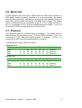
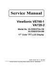
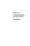
TSC02
Touch Screen
Controller Card
Contents
Contents........................................................................................................ 3
1. Introduction ............................................................................................. 4
2. Hardware Description ............................................................................. 5
2.1. Serial Connector ............................................................................ 5
2.2. Serial Interface ............................................................................... 5
2.3. Microcontroller................................................................................ 6
2.4. Power Supply ................................................................................. 6
2.5. Touch Screen Connector ............................................................... 7
2.6. Default Configuration Jumpers....................................................... 7
3. Parameters............................................................................................... 8
3.1. Filtering .......................................................................................... 8
3.2. Hi/Lo filtering .................................................................................. 8
3.3. Number of wires ............................................................................. 8
3.4. Min/Max.......................................................................................... 8
3.5. Touch mode ................................................................................... 8
3.6. Baud rate........................................................................................ 9
3.7. Protocol .......................................................................................... 9
4. Communication ..................................................................................... 10
4.1. Command word 00....................................................................... 11
4.2. Command word 01....................................................................... 11
4.3. Read back .................................................................................... 11
5. Test programs ....................................................................................... 12
5.1. TCOM........................................................................................... 12
5.2. TDRAW ........................................................................................ 12
6. Troubleshooting .................................................................................... 13
User's Manual Version 1.3 April 6, 1999
3
4
JP 2
C1
3 3p
B a u d ra te
1
2
3
P ro toc o l
1
2
3
VCC
VCC
X+
YXY+
2400
9600
5 -pa ck et
3 -pa ck et
15
4
14
17
18
1
2
3
16
RB0
RB1
RB2
RB3
RB4
RB5
RB6
RB7
P IC 1 6C 7 11
O SC2
M C LR
V CC G ND
RA0
RA1
RA2
RA3
RA4
O SC1
U1
RX TTL
TXTTL
5
6
7
8
9
10
11
12
13
T R IX E L L td .
GND
X+
XY+
YXY
T2
NPN
C h eck ed by
L1
L2
L3
L4
L5
10 0 k
R4
R5
4 k7
T1
PN P
R ad li F e ren c
P in te r G a b o r
R2
100k
R3
100k
D esig ned b y
GND
PROT
SPE ED
XY
RX TTL
T X TTL
100k
R1
C o nn e ct U 1 /1 0 to V C C
fo r in v ertin g in terfac e
T S C 0 2 S in gle ch ip to u ch sc re en co n tro ller
C2
33 p
1M H z
N Z C T B /1 .0 0 0 0 /J
F arn ell: 5 7 3 -5 4 1
X1
VCC
SPEED
GND
VCC
PRO T
GND
JP 1
D e fa ult c o n figu ratio n
C4
10n
RX D
TXD
DTR
C5
10n
C6
10n
Z1
3V 3
1 of 1
Sh eet:
C3
10u
C7
10n
8 0 -0 15 4
V CC
RT S
RXD
TXD
D TR
GND
1
2
3
4
5
V 1 .2
J2
X+ / X+
X- / XY + / 5W
Y- / Y+
NC / YT O U C H 4 /5
GND
DTR
RT S
J1
D CD
RXD
TX D
D TR
GND
D SR
RT S
C TS
RI
S E R IA L PO RT
0 2 /0 1 /1 9 9 9
D ate:
C8
10n
100
100
R6
R7
1
2
3
4
5
6
7
8
9
1. Introduction
TSC02 is a high speed single chip touch screen controller. It is usually
integrated into the LCD controller card or to the LCD itself, but available as a
stand-alone evaluation card too. This manual explains the connection and
working of the stand-alone card.
TSC02 Touch Screen Controller Card
2. Hardware Description
2.1. Serial Connector
RXD
TXD
DTR
GND
RT S
1
2
3
4
5
6
7
8
9
J1
DCD
RXD
TXD
DTR
GND
D SR
RT S
CTS
RI
S E R IA L P O RT
TSC02 is connected to the RS232 interface by a standard 9-pin D-type
connector. Only the RXD and TXD lines are used for communication. DTR
is used for power supply generation.
2.2. Serial Interface
DTR
C on n e ct U 1 /1 0 to V C C
fo r in v ertin g in te rfa ce
R3
100k
T1
PN P
R2
100k
TXTTL
R1
100k
TXD
T2
N PN
R X TT L
R5
4k7
R4
RXD
100k
The serial interface is a simple level shifter circuit, similar to those used in
mice. The microcontroller can use either normal or inverted signals.
Connect U1/10 to VCC, if you are using a true inverting RS232 driver IC.
User's Manual Version 1.3 April 6, 1999
5
2.3. Microcontroller
U1
X+
YXY+
X1
C2
3 3p
17
18
1
2
3
16
1M Hz
C1
3 3p
RA0
RA1
RA2
RA3
RA4
O SC1
15
4
14
VCC
VCC
RB0
RB1
RB2
RB3
RB4
RB5
RB6
RB7
O SC2
M CLR
VCC GND
6
7
8
9
10
11
12
13
R X T TL
TXTTL
GND
PRO T
SPEED
XY
5
P IC 1 6C 7 11
The heart of the TSC02 is the microcontroller. It handles the touch screen
and communicates with the host computer
2.4. Power Supply
VCC
R7
RT S
100
R6
DTR
100
Z1
3V 3
C3
10u
GND
Power supply is derived from the DTR and RTS line. For normal operation
DTR and RTS must be set to high. The current required is 20mA. VCC is 35.5V.
6
TSC02 Touch Screen Controller Card
2.5. Touch Screen Connector
X+
XY+
YXY
L1
L2
L3
L4
L5
1
2
3
4
5
C4
10n
GND
C5
10n
C6
10n
C7
10n
J2
X+ / X+
X- / XY + / 5W
Y- / Y+
NC / YTO U C H 4 /5
C8
10n
The touch screen is connected to a pin header. TSC02 supports 4 and 5
wire touch screens. The next picture shows the connection method.
YX+
Y-
X-
X+
XFront view
Y+
5W
Y+
2.6. Default Configuration Jumpers
D efa u lt co n figu ratio n
VCC
PRO T
GND
1
2
3
JP 1
3 -pac k et
5 -pac k et
P ro toc o l
VCC
SPEED
GND
1
2
3
JP 2
9600
2400
B a u d ra te
The power-up default configuration is determined by JP1 nad JP2 jumpers.
If the TSC02 controller is integrated into the LCD these jumpers are usually
hard wired.
User's Manual Version 1.3 April 6, 1999
7
3. Parameters
The operation of the TSC02 is controlled by a set of parameter.
3.1. Filtering
The filtering option selects the number of samples the controller take at each
point. The average of these samples determine the touch position. Higher
value means lower speed, but better accuracy. Default value: 32.
3.2. Hi/Lo filtering
Hi/Lo filtering uses lower filtering value at high velocities, and higher filtering
value at low velocities. It improves the overall performance of the controller.
Default: ON.
3.3. Number of wires
TSC02 currently supports only 4 wire touch screen interface. If TSC02
supports 5, 7 and 8 wire interface in the future then automatic recognition will
be used. The command field that changes the number of wires is ignored.
3.4. Min/Max
Min/Max controls the sensitivity of TSC02. In high noise environment TSC02
works more reliably, though less accurately, if set to HIGH. Default: HIGH.
3.5. Touch mode
Touch mode
A continuous stream of pen down codes is sent at touch down.
One pen up code at touch up.
This is the default mode.
Untouch up mode:
No code is sent at touch down
One pen down and immediately one pen up code is sent at touch up.
Untouch down mode
One pen down and immediately one pen up code is sent at touch down.
No code is sent at touch up.
8
TSC02 Touch Screen Controller Card
3.6. Baud rate
TSC02 supports two baud rates: 2400 baud and 9600 baud, however at
2400 baud it works too slowly, therefore it is not recommended. Be careful
when switching baud rate, because the command is acknowledged at the old
baud rate, and only after that will the new baud rate be used. The default
value is determined by the connection of pin 12 of the TSC02 controller. If
pin 12 is connected to VCC, then the default baud rate is 9600. If pin 12 is
connected to GND, then the default baud rate is 2400.
3.7. Protocol
Most programs uses the 3-packet protocol nowadays. The default value is
determined by the connection of pin 11 of the TSC02 controller. If pin 11 is
connected to VCC, then the default protocol is 3-packet. If pin 11 is
connected to GND, then the default protocol is 5-packet.
3-packet protocol (also called new mode).
pen down code
Bit #
Sync
Data
Data
7
1
0
0
6
1
X6
Y6
5
X9
X5
Y5
4
X8
X4
Y4
3
X7
X3
Y3
2
Y9
X2
Y2
1
Y8
X1
Y1
0
Y7
X0
Y0
Description
Packet 1
Packet 2
Packet 3
pen up code
Bit #
Sync
Data
Data
7
1
0
0
6
0
X6
Y6
5
X9
X5
Y5
4
X8
X4
Y4
3
X7
X3
Y3
2
Y9
X2
Y2
1
Y8
X1
Y1
0
Y7
X0
Y0
Description
Packet 1
Packet 2
Packet 3
User's Manual Version 1.3 April 6, 1999
9
5-packet protocol (also called old mode)
pen down code
Bit #
Sync
Data
Data
Data
Data
pen up code
Bit #
Sync
Data
Data
7
1
0
X9
0
Y9
6
1
0
X8
0
Y8
5
1
0
X7
0
Y7
4
1
0
X6
0
Y6
3
1
0
X5
0
Y5
2
1
0
X4
0
Y4
1
1
X1
X3
Y1
Y3
0
1
X0
X2
Y0
Y2
Description
Packet 1
Packet 2
Packet 3
Packet 4
Packet 5
7
1
1
1
6
1
1
1
5
1
1
1
4
1
1
1
3
1
1
1
2
1
1
1
1
1
1
1
0
1
0
0
Description
Packet 1
Packet 2
Packet 3
4. Communication
The TSC02 communicates at 9600 baud, 8 data bits, 1 stop bit, no parity
format over the RS232 serial line. Parameters can be set the following way:
1. Send SOH code (01H).
2. Skip the echoed SOH code (01H).
3. Wait for ACK code (06H).
4. If no ACK is received for 100 ms then the TSC02 is not connected.
5. Within 100 ms send the command code.
6. Skip the echoed command code.
7. Wait for ACK code (06H).
8. If no ACK is received for 100 ms then the TSC02 is not connected.
9. Within 100 ms send CR code (0DH).
10. Skip the echoed CR code (0DH).
11. Wait for ACK code (06H).
12. If no ACK is received for 100 ms then the TSC02 is not connected.
Please note that the RS232 transmit and receive lines are connected in a
way that you receive every sent byte in the same time.
10
TSC02 Touch Screen Controller Card
4.1. Command word 00
Bit #
Filtering
Filtering
Filtering
Filtering
Hi/Lo filter
Hi/Lo filter
# Wires
# Wires
# Wires
# Wires
Min/Max
Min/Max
7
0
0
0
0
0
0
0
0
0
0
0
0
6
0
0
0
0
0
0
0
0
0
0
0
0
5
4
3
2
1
0
0
1
1
0
0
1
0
1
Description
4
8
16
32
Off
On
7
5
8
4
HIGH
LOW
1
0
0
1
1
0
0
1
0
1
Description
Reserved
Untouch up
Untouch down
Touch
Reserved
2400
Reserved
9600
5-packet
3-packet
Reserved
Reserved
0
1
0
0
1
1
0
1
0
1
0
1
4.2. Command word 01
Bit #
Mode
Mode
Mode
Mode
Baud rate
Baud rate
Baud rate
Baud rate
Protocol
Protocol
Reserved
Reserved
7
0
0
0
0
0
0
0
0
0
0
0
0
6
1
1
1
1
1
1
1
1
1
1
1
1
5
4
3
2
0
0
1
1
0
1
0
1
0
1
0
1
4.3. Read back
The 0F0H command requests parameter readback. After acknowledging the
command TSC02 returns 3 bytes:
1. Command word 0 (# Wires are set to the autodetected value)
2. Command word 1
3. Version number (V1.3 is returned as 12H)
Additional bytes may be returned by future versions.
User's Manual Version 1.3 April 6, 1999
11
5. Test programs
Test programs are written for DOS. Source code is also available.
5.1. TCOM
TCOM simply displays data received from the touch overlay in hex and text
format. It is also capable of sending data to touch overlay. Any byte entered
on the keyboard are sent to the touch controller as command code enclosed
in SOH and CR. The utility accesses the touch overlay controller directly,
without any drivers or filtering.
Usage:
TCOM /A:address /I:irq
or:
TCOM /n
where address is the address of the serial line the touch overlay controller is
connected to, and irq is the interrupt request line number. Standard COMn
serial port can also be selected by /n.
5.2. TDRAW
TDRAW interprets the coordinates and shows them graphically. This utility
accesses the touch overlay controller directly, without any drivers or filtering.
This program requires a standard VGA card.
Usage:
TDRAW /A:address /I:irq
or:
TDRAW /n
where address is the address of the serial line the touch overlay controller is
connected to, and irq is the interrupt request line number. Standard COMn
serial port can also be selected by /n.
There is no way of calibrating the program. It is normal that the area of the
touch screen does not fill the entire screen. TDRAW works in 3-packet
mode only.
12
TSC02 Touch Screen Controller Card
6. Troubleshooting
If the touch screen controller does not work, please follow the checklist:
1. Restart the computer in DOS only mode.
2. Set the baud rate. (MODE COM1:9600,n,8,1)
3. Start TCOM. Use port and interrupt settings you think good.
4. Read back parameters by sending F0.
The touch screen should return something like
01 06 F0 06 0D 06 3F 5F 12
5. If you receive nothing, then the touch screen controller is not
connected to the serial line you try to use, or uses a different IRQ.
6. If you receive 01 only, then the touch screen controller is connected,
but uses different speed.
7. Interpret the returned command words.
3F: HIGH Min/Max filter, 4 wire interface, Hi/Lo filter ON, filtering 32.
5F: 3-packet protocol, 9600 baud, touch mode.
8. Touch the screen, and check the returned bytes. If nothing happens
then the touch screen is not connected properly.
9. Set touch mode, 3-packet protocol, and exit TCOM.
10. Start TDRAW, and draw something nice. It is normal that the used
area does not fill the entire screen. The screen may display mirrored
image, depending the connection method. But if you draw a line on
the touch screen then you should see a dotted line on the display
screen.
If the touch screen works with TCOM and TDRAW, but not in the
environment you try to use it then the drivers are not installed properly.
Please refer to the driver documentation.
User's Manual Version 1.3 April 6, 1999
13