1
AllenBradley
DF1 Protocol and
Command Set
Reference
Manual
Important User
Information
Because of the variety of uses for the products described in this
publication, those responsible for the application and use of this
control equipment must satisfy themselves that all necessary steps
have been taken to assure that each application and use meets all
performance and safety requirements, including any applicable laws,
regulations, codes and standards.
The illustrations, charts, sample programs and layout examples
shown in this guide are intended solely for purposes of example.
Since there are many variables and requirements associated with any
particular installation, Allen-Bradley does not assume responsibility
or liability (to include intellectual property liability) for actual use
based upon the examples shown in this publication.
Allen-Bradley publication SGI-1.1, Safety Guidelines for the
Application, Installation, and Maintenance of Solid-State Control
(available from your local Allen-Bradley office), describes some
important differences between solid-state equipment and
electromechanical devices that should be taken into consideration
when applying products such as those described in this publication.
Reproduction of the contents of this copyrighted publication, in
whole or in part, without written permission of Allen-Bradley
Company, Inc., is prohibited.
Throughout this manual we use notes to make you aware of safety
considerations:
!
ATTENTION: Identifies information about practices
or circumstances that can lead to personal injury or
death, property damage or economic loss.
Attention statements help you to:
• identify a hazard
• avoid the hazard
• recognize the consequences
Important:
Identifies information that is critical for successful
application and understanding of the product.
PLC-5, DH+, PLC-2, PLC-3, PLC, SLC 500, SLC, SLC 5/01, SLC 5/02, SLC 5/03, SLC 5/04, ControlNet, MicroLogix, and
PLC-2/15 are trademarks of Allen-Bradley Company, Inc.
All other trademarks are property of their respective companies.
Summary of Changes
What's Changed in This
Document
About This Document
This document contains important information concerning the DF1
Protocol and Command Set Reference Manual.
This information extends and explains information provided in the
Data Highway/Data Highway Plust/DH-485 Communication
Protocol and Command Set Reference Manual, publication
1770-6.5.16 — November 1991
Changes to this document are indicated by a revision bar in the
margin.
Changes to This
Document
The “look and feel” of your Allen-Bradley documentation has
changed! We’re constantly trying to improve our documentation to
make it more usable for you. If you have questions or comments
about this document, complete the enclosed Publication Problem
Report. In addition, we’ve also made the following changes to
publication 1770-6.5.16:
Change
Description
Reference
organization
We've reorganized the reference manual to make it easier to find
information. We include a map" of this new organization.
Preface, page P-2
commands
We've added and updated the communication commands. We've
also organized them alphabetically. Additional commands include:
•apply port configuration
•change mode
•close file
•disable forces
•get edit resources
•initialize memory
•open file
•protected typed logical read with three address fields
•protected typed logical write with three address fields
•read diagnostic counters
•read section size
•return edit resource
Chapter 7, Communication Commands"
Publication 17706.5.16 - October 1996
Table of Contents
What's Changed in This Document . . . . . . . . . . . . . .
soc-i
About This Document . . . . . . . . . . . . . . . . . . . . . . . . . . . . .
Changes to This Document . . . . . . . . . . . . . . . . . . . . . . . . .
soc-i
soc-i
About This Manual . . . . . . . . . . . . . . . . . . . . . . . . . . .
P-1
Purpose of This Manual . . . . . . . . . . . . . . . . . . . . . . . . . . .
Who Should Use This Manual . . . . . . . . . . . . . . . . . . . . . . .
What This Manual Contains . . . . . . . . . . . . . . . . . . . . . . . .
Terms and Abbreviations . . . . . . . . . . . . . . . . . . . . . . . . . .
Related Publications . . . . . . . . . . . . . . . . . . . . . . . . . . . . . .
Related Products . . . . . . . . . . . . . . . . . . . . . . . . . . . . . . . .
Conventions Used in This Manual . . . . . . . . . . . . . . . . . . . .
P-1
P-1
P-2
P-3
P-3
P-4
P-5
Network Layers . . . . . . . . . . . . . . . . . . . . . . . . . . . . .
1-1
Physical Layer . . . . . . . . . . . . . . . . . . . . . . . . . . . . . . . . . .
DF1 Link . . . . . . . . . . . . . . . . . . . . . . . . . . . . . . . . . . . .
Network Link . . . . . . . . . . . . . . . . . . . . . . . . . . . . . . . . .
DH Link . . . . . . . . . . . . . . . . . . . . . . . . . . . . . . . . . .
DH+ Link . . . . . . . . . . . . . . . . . . . . . . . . . . . . . . . . . .
DH485 Link . . . . . . . . . . . . . . . . . . . . . . . . . . . . . . . .
Software Layers . . . . . . . . . . . . . . . . . . . . . . . . . . . . . . . . .
Datalink Layer . . . . . . . . . . . . . . . . . . . . . . . . . . . . . . .
Application Layer . . . . . . . . . . . . . . . . . . . . . . . . . . . . . .
Message Packet Structure . . . . . . . . . . . . . . . . . . . . . . . . .
Command and Reply Message . . . . . . . . . . . . . . . . . . . .
Message Priority . . . . . . . . . . . . . . . . . . . . . . . . . . . . . .
Delivery Order of Commands . . . . . . . . . . . . . . . . . . . . .
Types of Commands . . . . . . . . . . . . . . . . . . . . . . . . . . .
Error Codes . . . . . . . . . . . . . . . . . . . . . . . . . . . . . . . . . .
1-2
1-2
1-2
1-3
1-5
1-6
1-7
1-7
1-8
1-9
1-9
1-10
1-10
1-11
1-11
Understanding DF1 Protocol . . . . . . . . . . . . . . . . . . .
2-1
DF1 Protocol . . . . . . . . . . . . . . . . . . . . . . . . . . . . . . . . . . .
Halfduplex Protocol . . . . . . . . . . . . . . . . . . . . . . . . . . . .
Fullduplex Protocol . . . . . . . . . . . . . . . . . . . . . . . . . . . .
Character Transmission . . . . . . . . . . . . . . . . . . . . . . . . . . .
Transmission Symbols . . . . . . . . . . . . . . . . . . . . . . . . . . . .
2-2
2-2
2-4
2-5
2-6
ii
Table of Contents
Using Halfduplex Protocols to Send and
Receive Messages . . . . . . . . . . . . . . . . . . . . . . .
3-1
Halfduplex Protocol Message Transmission . . . . . . . . . . . .
Transmitter and Receiver Message Transfer . . . . . . . . . . . .
Halfduplex Protocol Environment . . . . . . . . . . . . . . . . . . . .
Message Characteristics . . . . . . . . . . . . . . . . . . . . . . . . . .
Master Polling Responsibilities . . . . . . . . . . . . . . . . . . . . . .
Duplicate Detection . . . . . . . . . . . . . . . . . . . . . . . . . . . .
Inactive Slave Polling . . . . . . . . . . . . . . . . . . . . . . . . . . .
Full Sinks . . . . . . . . . . . . . . . . . . . . . . . . . . . . . . . . . . .
Simplified Network Layer . . . . . . . . . . . . . . . . . . . . . . . .
Slave Transceiver Actions . . . . . . . . . . . . . . . . . . . . . . . . . .
HalfDuplex Protocol Diagrams . . . . . . . . . . . . . . . . . . . . . .
Normal Message Transfer . . . . . . . . . . . . . . . . . . . . . . . .
Message Transfer with Invalid BCC/CRC . . . . . . . . . . . . .
Message Transfer with ACK Destroyed . . . . . . . . . . . . . .
Poll with No Message Available . . . . . . . . . . . . . . . . . . . .
Poll with Message Returned . . . . . . . . . . . . . . . . . . . . . .
Duplicate Message Transmission . . . . . . . . . . . . . . . . . .
Message Sink Full, Case 1 . . . . . . . . . . . . . . . . . . . . . . .
Message Sink Full, Case 2 . . . . . . . . . . . . . . . . . . . . . . .
3-2
3-3
3-3
3-7
3-7
3-7
3-7
3-8
3-8
3-9
3-11
3-12
3-12
3-13
3-13
3-14
3-15
3-16
3-17
Using Fullduplex Protocol to Send and
Receive Messages . . . . . . . . . . . . . . . . . . . . . . .
4-1
Fullduplex Protocol Message Transmission . . . . . . . . . . . . .
Fullduplex Protocol Environment . . . . . . . . . . . . . . . . . . . .
Message Characteristics . . . . . . . . . . . . . . . . . . . . . . . . . .
Transmitter and Receiver Message Transfer . . . . . . . . . . . .
How the Transmitter Operates . . . . . . . . . . . . . . . . . . . . .
How the Receiver Operates . . . . . . . . . . . . . . . . . . . . . .
Fullduplex Protocol Diagrams . . . . . . . . . . . . . . . . . . . . . . .
Normal Message Transfer . . . . . . . . . . . . . . . . . . . . . . . .
Message Transfer with NAK . . . . . . . . . . . . . . . . . . . . . .
Message Transfer with Timeout and ENQ . . . . . . . . . . . . .
Message Transfer with ReTransmission . . . . . . . . . . . . .
Message Transfer with Message Sink Full . . . . . . . . . . . .
Message Transfer with NAK on Reply . . . . . . . . . . . . . . .
Message Transfer with Timeout and ENQ for the Reply . . .
Message Transfer with Message Source Full on the Reply .
4-2
4-3
4-4
4-4
4-5
4-7
4-10
4-10
4-11
4-12
4-13
4-14
4-15
4-16
4-17
Table of Contents
iii
Datalink Layer Message Frames . . . . . . . . . . . . . . . .
5-1
Halfduplex Protocol Message Frames . . . . . . . . . . . . . . . . .
Polling Frame . . . . . . . . . . . . . . . . . . . . . . . . . . . . . . . .
Master Message Frame . . . . . . . . . . . . . . . . . . . . . . . . .
Slave Message Frame . . . . . . . . . . . . . . . . . . . . . . . . . .
Fullduplex Protocol Message Frames . . . . . . . . . . . . . . . . .
From user application program . . . . . . . . . . . . . . . . . . . .
From common application routines . . . . . . . . . . . . . . . . .
Datalink layer frame . . . . . . . . . . . . . . . . . . . . . . . . . . .
BCC and CRC Fields . . . . . . . . . . . . . . . . . . . . . . . . . . . . .
BCC Field . . . . . . . . . . . . . . . . . . . . . . . . . . . . . . . . . . .
Halfduplex protocol example . . . . . . . . . . . . . . . . . . .
Fullduplex protocol example . . . . . . . . . . . . . . . . . . . .
CRC Field . . . . . . . . . . . . . . . . . . . . . . . . . . . . . . . . . . .
Fullduplex and halfduplex slave protocol . . . . . . . . . .
Halfduplex master protocol . . . . . . . . . . . . . . . . . . . . .
Use this frame to validate the CRC . . . . . . . . . . . . . . . .
5-2
5-2
5-2
5-2
5-3
5-3
5-3
5-3
5-4
5-4
5-4
5-5
5-6
5-7
5-7
5-7
Application Layer Message Packets . . . . . . . . . . . . .
6-1
How Your Application Program Sends and Receives Messages
Message Packet Format . . . . . . . . . . . . . . . . . . . . . . . . . . .
Command . . . . . . . . . . . . . . . . . . . . . . . . . . . . . . . . . . .
Reply . . . . . . . . . . . . . . . . . . . . . . . . . . . . . . . . . . . . . .
DST and SRC . . . . . . . . . . . . . . . . . . . . . . . . . . . . . . . .
Command . . . . . . . . . . . . . . . . . . . . . . . . . . . . . . . . . . .
Reply . . . . . . . . . . . . . . . . . . . . . . . . . . . . . . . . . . . . . .
CMD and FNC . . . . . . . . . . . . . . . . . . . . . . . . . . . . . . . .
STS and EXT STS . . . . . . . . . . . . . . . . . . . . . . . . . . . . .
TNS . . . . . . . . . . . . . . . . . . . . . . . . . . . . . . . . . . . . . . .
ADDR . . . . . . . . . . . . . . . . . . . . . . . . . . . . . . . . . . . . . .
SIZE . . . . . . . . . . . . . . . . . . . . . . . . . . . . . . . . . . . . . . .
6-2
6-3
6-3
6-3
6-4
6-4
6-4
6-5
6-6
6-7
6-8
6-8
Communication Commands . . . . . . . . . . . . . . . . . . . .
7-1
command name . . . . . . . . . . . . . . . . . . . . . . . . . . . . . . . . .
apply port configuration . . . . . . . . . . . . . . . . . . . . . . . . . . .
bit write (write bit) . . . . . . . . . . . . . . . . . . . . . . . . . . . . . . . .
change mode . . . . . . . . . . . . . . . . . . . . . . . . . . . . . . . . . .
close file . . . . . . . . . . . . . . . . . . . . . . . . . . . . . . . . . . . . . .
diagnostic status . . . . . . . . . . . . . . . . . . . . . . . . . . . . . . .
disable forces . . . . . . . . . . . . . . . . . . . . . . . . . . . . . . . . .
disable outputs . . . . . . . . . . . . . . . . . . . . . . . . . . . . . . . . .
download all request (download) . . . . . . . . . . . . . . . . . . . .
download completed . . . . . . . . . . . . . . . . . . . . . . . . . . . . .
download request (download privilege) . . . . . . . . . . . . . . . .
7-1
7-4
7-4
7-5
7-5
7-6
7-6
7-6
7-7
7-7
7-8
iv
Table of Contents
echo . . . . . . . . . . . . . . . . . . . . . . . . . . . . . . . . . . . . . . . .
enable outputs . . . . . . . . . . . . . . . . . . . . . . . . . . . . . . . . . .
enable PLC scanning . . . . . . . . . . . . . . . . . . . . . . . . . . . . .
enter download mode . . . . . . . . . . . . . . . . . . . . . . . . . . . .
enter upload mode . . . . . . . . . . . . . . . . . . . . . . . . . . . . . .
exit download/upload mode . . . . . . . . . . . . . . . . . . . . . . . . .
file read (read file) . . . . . . . . . . . . . . . . . . . . . . . . . . . . . . .
file write (write file) . . . . . . . . . . . . . . . . . . . . . . . . . . . . . . .
get edit resource . . . . . . . . . . . . . . . . . . . . . . . . . . . . . . . .
initialize memory . . . . . . . . . . . . . . . . . . . . . . . . . . . . . . .
modify PLC2 compatibility file . . . . . . . . . . . . . . . . . . . . . .
open file . . . . . . . . . . . . . . . . . . . . . . . . . . . . . . . . . . . . . .
physical read . . . . . . . . . . . . . . . . . . . . . . . . . . . . . . . . . .
physical write . . . . . . . . . . . . . . . . . . . . . . . . . . . . . . . . .
protected bit write . . . . . . . . . . . . . . . . . . . . . . . . . . . . . . .
protected typed file read . . . . . . . . . . . . . . . . . . . . . . . . . . .
protected typed file write . . . . . . . . . . . . . . . . . . . . . . . . . . .
protected typed logical read with three address fields . . . . . .
protected typed logical write with three address fields . . . . . .
protected write . . . . . . . . . . . . . . . . . . . . . . . . . . . . . . . . .
read bytes physical (physical read) . . . . . . . . . . . . . . . . . . .
read diagnostic counters . . . . . . . . . . . . . . . . . . . . . . . . .
read link parameters . . . . . . . . . . . . . . . . . . . . . . . . . . . . .
read modifywrite (write bit) . . . . . . . . . . . . . . . . . . . . . . . .
readmodifywrite N . . . . . . . . . . . . . . . . . . . . . . . . . . . . .
read section size . . . . . . . . . . . . . . . . . . . . . . . . . . . . . . . .
reset diagnostic counters . . . . . . . . . . . . . . . . . . . . . . . . . .
restart request (restart) . . . . . . . . . . . . . . . . . . . . . . . . . . . .
return edit resource . . . . . . . . . . . . . . . . . . . . . . . . . . . . . .
set data table size . . . . . . . . . . . . . . . . . . . . . . . . . . . . . .
set ENQs . . . . . . . . . . . . . . . . . . . . . . . . . . . . . . . . . . . . .
set link parameters . . . . . . . . . . . . . . . . . . . . . . . . . . . . . .
set NAKs . . . . . . . . . . . . . . . . . . . . . . . . . . . . . . . . . . . . .
set CPU mode . . . . . . . . . . . . . . . . . . . . . . . . . . . . . . . . .
set timeout . . . . . . . . . . . . . . . . . . . . . . . . . . . . . . . . . . . .
set variables . . . . . . . . . . . . . . . . . . . . . . . . . . . . . . . . . . .
shutdown . . . . . . . . . . . . . . . . . . . . . . . . . . . . . . . . . . . . .
typed read (read block) . . . . . . . . . . . . . . . . . . . . . . . . . . .
typed write (write block) . . . . . . . . . . . . . . . . . . . . . . . . . . .
unprotected bit write . . . . . . . . . . . . . . . . . . . . . . . . . . . . .
unprotected read . . . . . . . . . . . . . . . . . . . . . . . . . . . . . . .
unprotected write . . . . . . . . . . . . . . . . . . . . . . . . . . . . . . .
upload all request (upload) . . . . . . . . . . . . . . . . . . . . . . . . .
upload completed . . . . . . . . . . . . . . . . . . . . . . . . . . . . . . . .
upload . . . . . . . . . . . . . . . . . . . . . . . . . . . . . . . . . . . . . . .
7-8
7-9
7-9
7-9
7-10
7-10
7-10
7-11
7-11
7-12
7-12
7-13
7-13
7-14
7-15
7-16
7-16
7-17
7-18
7-19
7-19
7-19
7-20
7-20
7-21
7-22
7-22
7-23
7-24
7-24
7-25
7-25
7-25
7-26
7-27
7-27
7-28
7-28
7-30
7-30
7-31
7-32
7-33
7-34
7-34
Table of Contents
v
word range read (read block) . . . . . . . . . . . . . . . . . . . . . .
word range write (write block) . . . . . . . . . . . . . . . . . . . . . . .
write bytes physical (physical write) . . . . . . . . . . . . . . . . . .
PLC5 Type/Data Parameter Examples . . . . . . . . . . . . . . . .
SLC 500 Information . . . . . . . . . . . . . . . . . . . . . . . . . . . . .
Reading and Writing SLC 500 Data . . . . . . . . . . . . . . . . . . .
Reading and Writing SLC 500 Data (using PLC2 terminology)
7-34
7-35
7-35
7-36
7-38
7-38
7-38
Message Packet Status Codes (STS, EXT STS) . . . . .
8-1
STS Byte . . . . . . . . . . . . . . . . . . . . . . . . . . . . . . . . . . . . . .
Local STS Error Codes . . . . . . . . . . . . . . . . . . . . . . . . . .
Remote STS Error Codes . . . . . . . . . . . . . . . . . . . . . . . .
EXT STS Byte . . . . . . . . . . . . . . . . . . . . . . . . . . . . . . . . . .
DH485 EXT STS Codes . . . . . . . . . . . . . . . . . . . . . . . . .
Remote STS and EXT STS Codes . . . . . . . . . . . . . . . . . . . .
Remote STS Codes from a PLC2 or 1774PLC Processor
Remote STS and EXT STS Codes from a PLC3 Processor
8-2
8-2
8-3
8-3
8-5
8-5
8-5
8-6
Diagnostic Counters . . . . . . . . . . . . . . . . . . . . . . . . .
9-1
1747 Cat. Nos. . . . . . . . . . . . . . . . . . . . . . . . . . . . . . . . . . .
9-3
1747KE DH485 Diagnostic Counters . . . . . . . . . . . . . . .
9-3
1747L20, L30, L40, L511, L514, L524, (SLC 500, 5/01, and
5/02 processors), 1747PA2x (SLC APS COM1), 1770KF3,
and 1784KR DH485 Diagnostic Counters . . . . . . . . .
9-3
1747L541, L542, and L543 (SLC 5/04 processors)
DH+ Diagnostic Counters . . . . . . . . . . . . . . . . . . . . .
9-4
1747L541, L542, and L543 (SLC 5/03 and 5/04 processors)
DH485 Diagnostic Counters . . . . . . . . . . . . . . . . . . . .
9-5
1747L541, L542, and L543 (SLC 5/03 and SLC 5/04 processors)
DF1 Diagnostic Counters . . . . . . . . . . . . . . . . . . . . . .
9-6
1761 Cat. Nos. . . . . . . . . . . . . . . . . . . . . . . . . . . . . . . . . . .
9-7
1761L16AWA, L16BBB, L16BWB, L32AWA, L32BWA, L32BWB
(MicroLogix 1000 processors, Series C or later) DH485 Diagnostic
Counters . . . . . . . . . . . . . . . . . . . . . . . . . . . . . . . . .
9-7
1761L16AWA, L16BBB, L16BWB, L32AWA, L32BWA, L32BWB
(MicroLogix 1000 processors) DF1 Diagnostic Counters
9-7
1770 Cat. Nos. . . . . . . . . . . . . . . . . . . . . . . . . . . . . . . . . . .
9-8
1770KF2 and 1771KE/KF DH and Asynchronous Link Diagnostic
Counters . . . . . . . . . . . . . . . . . . . . . . . . . . . . . . . . .
9-8
1770KF2 and 1785KE DH+ and Asynchronous Link Diagnostic
Counters . . . . . . . . . . . . . . . . . . . . . . . . . . . . . . . . .
9-11
1770KFC DF1 Diagnostic Counters . . . . . . . . . . . . . . . .
9-13
1771 Cat. Nos. . . . . . . . . . . . . . . . . . . . . . . . . . . . . . . . . . .
9-14
1771KA, 1771KA2, and 1774KA DH Diagnostic Counters
9-14
1771KC DH Diagnostic Counters . . . . . . . . . . . . . . . . . .
9-16
1771KG,KGM Diagnostic Counters . . . . . . . . . . . . . . . .
9-19
vi
Table of Contents
1775 Cat. Nos. . . . . . . . . . . . . . . . . . . . . . . . . . . . . . . . . . .
1775KA,S5,SR5 DH Diagnostic Counters . . . . . . . . . . .
1775S5,SR5 DH+ Diagnostic Counters . . . . . . . . . . . . .
1779 Cat. Nos. . . . . . . . . . . . . . . . . . . . . . . . . . . . . . . . . . .
1779KP5 DH+ Diagnostic Counters . . . . . . . . . . . . . . . .
1784 Cat. Nos. . . . . . . . . . . . . . . . . . . . . . . . . . . . . . . . . . .
1784KT and 1784KT2 DH+ Diagnostic Counters . . . . . .
1785 Cat. Nos. . . . . . . . . . . . . . . . . . . . . . . . . . . . . . . . . . .
1785KA DH Diagnostic Counters . . . . . . . . . . . . . . . . . .
1785KA DH+ Diagnostic Counters . . . . . . . . . . . . . . . . .
1785KA3 DH+ Diagnostic Counters . . . . . . . . . . . . . . . .
1785KA5 DH+ Diagnostic Counters . . . . . . . . . . . . . . . .
1785KA5 DH485 Diagnostic Counters . . . . . . . . . . . . . .
1785L11B, L20B, L30B, L40B, L60B, and L80B DH+ Channel
Diagnostic Counters . . . . . . . . . . . . . . . . . . . . . . . . .
1785L20E, L40E, L40L, L60L, L80E DH+ Diagnostic
Counters . . . . . . . . . . . . . . . . . . . . . . . . . . . . . . . . .
5250 Cat. Nos. . . . . . . . . . . . . . . . . . . . . . . . . . . . . . . . . . .
5250LP1, LP2, LP3, LP4 DH+ Diagnostic Counters . . .
9-21
9-21
9-23
9-24
9-24
9-25
9-25
9-26
9-26
9-27
9-28
9-29
9-30
Diagnostic Status Information . . . . . . . . . . . . . . . . . .
10-1
9-30
9-32
9-33
9-33
1747 Cat. Nos. . . . . . . . . . . . . . . . . . . . . . . . . . . . . . . . . . .
10-2
1747KE Status Bytes . . . . . . . . . . . . . . . . . . . . . . . . . .
10-2
1747L20, L30, L40, L511, L514, L524 (SLC 500, SLC 5/01
and SLC 5/02 processors) Status Bytes . . . . . . . . . .
10-3
1747L532, L541, L542, L543 (SLC 5/03 and SLC 5/04 processors)
Status Bytes . . . . . . . . . . . . . . . . . . . . . . . . . . . . . .
10-4
1761, 1770, and 1771 Cat. Nos. . . . . . . . . . . . . . . . . . . . . .
10-5
1761L16AWA, L16BBB, L16BWB, L32AWA, L32BWA, L32BWB
(MicroLogix 1000 processors) Status Bytes . . . . . . . . .
10-6
1770KF3 Status Bytes . . . . . . . . . . . . . . . . . . . . . . . . .
10-7
1771KA2, KA, KC/KD, KE, KF, KG, KGM, 1770KF2
Status Bytes . . . . . . . . . . . . . . . . . . . . . . . . . . . . . . .
10-7
1773, 1775, and 1779 Cat. Nos. . . . . . . . . . . . . . . . . . . . . .
10-11
1773KA Status Bytes . . . . . . . . . . . . . . . . . . . . . . . . . .
10-11
1775KA, S5 and SR5 Status Bytes . . . . . . . . . . . . . . .
10-13
1779KP5 Status Bytes . . . . . . . . . . . . . . . . . . . . . . . . .
10-14
1784 Cat. Nos. . . . . . . . . . . . . . . . . . . . . . . . . . . . . . . . . . .
10-15
1784KR Status Bytes . . . . . . . . . . . . . . . . . . . . . . . . . .
10-15
1784KT, KT2 Status Bytes . . . . . . . . . . . . . . . . . . . . . .
10-15
1785 Cat. Nos. . . . . . . . . . . . . . . . . . . . . . . . . . . . . . . . . . .
10-16
1785KA Status Bytes . . . . . . . . . . . . . . . . . . . . . . . . . .
10-16
1785KA5 Status Bytes . . . . . . . . . . . . . . . . . . . . . . . . .
10-17
1785KA3 Status Bytes . . . . . . . . . . . . . . . . . . . . . . . . .
10-17
1785KE Status Bytes . . . . . . . . . . . . . . . . . . . . . . . . . .
10-19
Table of Contents
vii
1785LT (PLC5/15) and 6008LTV (PLC5 VME)
Status Bytes . . . . . . . . . . . . . . . . . . . . . . . . . . . . . .
1785LT3 (PLC5/12) and 1785LT2 (PLC5/25)
Status Bytes . . . . . . . . . . . . . . . . . . . . . . . . . . . . . .
1785L11B, L20B, L20E, L30B, L40B, L40E, L40L,
L60B, L60L Status Bytes . . . . . . . . . . . . . . . . . . . .
5130 Cat. Nos. . . . . . . . . . . . . . . . . . . . . . . . . . . . . . . . . . .
5130RM1,RM2 (PLC5/250) Status Bytes . . . . . . . . . . .
10-22
10-23
10-23
Data Encoding . . . . . . . . . . . . . . . . . . . . . . . . . . . . . .
11-1
Numbering Systems . . . . . . . . . . . . . . . . . . . . . . . . . . . . . .
Decimal . . . . . . . . . . . . . . . . . . . . . . . . . . . . . . . . . . . . .
Decimal Representation, Number 239 . . . . . . . . . . . . .
Binary . . . . . . . . . . . . . . . . . . . . . . . . . . . . . . . . . . . . . .
Binary Representation, Number 239 . . . . . . . . . . . . . .
Binary Coded Decimal . . . . . . . . . . . . . . . . . . . . . . . . . .
BCD Representation of Decimal 239 . . . . . . . . . . . . . .
Hexadecimal . . . . . . . . . . . . . . . . . . . . . . . . . . . . . . . .
Hexadecimal Representation of Decimal 423 . . . . . . . .
Octal . . . . . . . . . . . . . . . . . . . . . . . . . . . . . . . . . . . . . .
Octal Representation of Decimal 239 . . . . . . . . . . . . . .
Binary Floatingpoint . . . . . . . . . . . . . . . . . . . . . . . . . . .
Order of Transmission . . . . . . . . . . . . . . . . . . . . . . . . . . . .
A 16Bit Word in PLC Memory . . . . . . . . . . . . . . . . . . .
A 16Bit Computer Word with LefttoRight Byte and
Bit Order . . . . . . . . . . . . . . . . . . . . . . . . . . . . . . .
A 16Bit Computer Word with RighttoLeft Byte and
Bit Order . . . . . . . . . . . . . . . . . . . . . . . . . . . . . . .
A 16Bit Computer Word with LefttoRight Byte Order and
RighttoLeft Bit Order . . . . . . . . . . . . . . . . . . . . . .
11-2
11-2
11-2
11-3
11-3
11-3
11-3
11-4
11-4
11-5
11-5
11-5
11-6
11-7
Uploading and Downloading with AB Processors . . .
12-1
Uploading from the Processor . . . . . . . . . . . . . . . . . . . . . . .
Uploading from a PLC2 Processor . . . . . . . . . . . . . . . . .
Uploading from a PLC3 Processor . . . . . . . . . . . . . . . . .
Uploading from a PLC5 Processor . . . . . . . . . . . . . . . . .
Procedure 1 PLC5/15/B processors, revision E
and earlier . . . . . . . . . . . . . . . . . . . . . . . . . . . . . .
Procedure 2 . . . . . . . . . . . . . . . . . . . . . . . . . . . . . . . .
Uploading from an SLC 500 Processor . . . . . . . . . . . . . .
Downloading to the Processor . . . . . . . . . . . . . . . . . . . . . . .
Downloading to a PLC2 Processor . . . . . . . . . . . . . . . . .
Downloading to a PLC3 Processor . . . . . . . . . . . . . . . . .
Downloading to a PLC5 Processor . . . . . . . . . . . . . . . . .
Procedure 1 (PLC5/15/B rev E and earlier) . . . . . . . . .
Procedure 2 . . . . . . . . . . . . . . . . . . . . . . . . . . . . . . . .
12-2
12-2
12-2
12-3
10-20
10-21
11-7
11-7
11-7
12-4
12-5
12-6
12-6
12-7
12-8
12-8
12-9
12-10
viii
Table of Contents
Downloading to an SLC 500 Processor . . . . . . . . . . . . . .
Procedure 1 SLC 500, SLC 5/01 and SLC 5/02
Processors . . . . . . . . . . . . . . . . . . . . . . . . . . . . . .
Procedure 2 SLC 5/03 and SLC 5/04 Processors . . .
12-10
12-11
12-12
PLC Addressing . . . . . . . . . . . . . . . . . . . . . . . . . . . .
13-1
PLC2/1774PLC Addressing . . . . . . . . . . . . . . . . . . . . . . .
PLC2/1774PLC Logical Addressing . . . . . . . . . . . . . . . .
PLC2 Physical Addressing . . . . . . . . . . . . . . . . . . . . . . .
1774PLC Physical Addressing . . . . . . . . . . . . . . . . . . . .
PLC3 Addressing . . . . . . . . . . . . . . . . . . . . . . . . . . . . . . .
PLC3 Logical Addressing . . . . . . . . . . . . . . . . . . . . . . . .
PLC3 Physical Addressing . . . . . . . . . . . . . . . . . . . . . . .
PLC3 Symbolic Addressing . . . . . . . . . . . . . . . . . . . . . .
PLC5 Addressing . . . . . . . . . . . . . . . . . . . . . . . . . . . . . . .
PLC5 Logical Addressing . . . . . . . . . . . . . . . . . . . . . . . .
PLC5 Logical Binary Addressing . . . . . . . . . . . . . . . .
PLC5/250 Logical Binary Addressing . . . . . . . . . . . . .
Logical ASCII Addressing . . . . . . . . . . . . . . . . . . . . . .
PLC5 Physical Addressing . . . . . . . . . . . . . . . . . . . . . . .
PLC5 Floating Point . . . . . . . . . . . . . . . . . . . . . . . . . . .
13-2
13-2
13-3
13-3
13-4
13-5
13-7
13-8
13-9
13-10
13-11
13-13
13-15
13-16
13-17
Line Monitor Examples . . . . . . . . . . . . . . . . . . . . . . .
14-1
Halfduplex Line Monitor Example . . . . . . . . . . . . . . . . . . . .
Message from master to slave and slave acknowledgement:
Message sent from slave to master in response to poll and
slave acknowledgement: . . . . . . . . . . . . . . . . . . . . . .
Poll with a DLE EOT in response: . . . . . . . . . . . . . . . . . .
Fullduplex PLC2 Line Monitor Example . . . . . . . . . . . . . . .
Fullduplex PLC3 Line Monitor Example . . . . . . . . . . . . . . .
14-2
14-2
ASCII Codes . . . . . . . . . . . . . . . . . . . . . . . . . . . . . . .
151
14-2
14-2
14-3
14-6
Preface
About This Manual
Read this preface to familiarize yourself with this manual.
This preface includes information on:
• the purpose of this manual
• who should use this manual
• what this manual contains
• terms and abbreviations used in this manual
• related publications
• related products
• conventions used in this manual
Purpose of This Manual
Use this manual to:
• program a DF1 driver for a computer to interface to
Allen-Bradley DF1 products and to proprietary networks via
protocol bridges
• write applications for 1784-KT, -KT2, -KTX, -KTXD, -PCMK
communication interfaces using standard
Rockwell Software Inc. (RSI) driver products
• troubleshoot your network
Who Should Use This
Manual
Read this manual before you attempt to write a DF1 driver, or before
attempting to troubleshoot your network. We assume that you are
already familiar with:
• your serial device
• Allen-Bradley PLC processors
Before you begin writing your driver, make sure you have:
• a pocket calculator that adds, subtracts, multiplies, and divides in
decimal, hexidecimal, octal, and binary
• a serial protocol analyzer for displaying actual hex bytes sent to
and from a DH, DH+, or DH485 module
"
Writing drivers
As an alternative to writing your own driver, RSI provides RSLINX
C SDK (cat. no. 9355-WABC) and INTERCHANGE (cat. nos.
9351-AIX, -DKTS, -HPUS, -OSF, -VS, -WES, -WKTS) software.
These products provide an application programmer’s interface (API)
and a complete set of drivers to communicate with Allen-Bradley
processors via Ethernet, DH, DH+, DH485, and DF1 serial links on
various hardware and operating system platforms.
17706.5.16 October, 1996
P–2
About This Manual
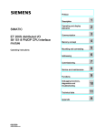
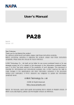
What This Manual
Contains
➊Network
Basics
Chapter 1,
Network Layers
This manual is divided into five units:
➋Protocol
➌Message
Packets
➍Module
Diagnostics
➎Reference
Chapter 2,
Understanding DF1
Protocol
Chapter 5,
Datalink Layer
Message Frames
Chapter 9,
Diagnostic Counters
Chapter 11,
Data Encoding
Chapter 3,
Using Halfduplex
Protocol to Send and
Receive Messages
Chapter 6,
Application Layer
Message Packets
Chapter 10,
Diagnostic Status
Information
Chapter 12,
Uploading and
Downloading
Chapter 4,
Using Fullduplex
Protocol to Send and
Receive Messages
Chapter 7,
Communication
Commands
Chapter 13,
PLC Addressing
Chapter 8,
Message Packet
Status Codes (STS,
EXT STS)
Chapter 14,
Line Monitor
Examples
Chapter 15,
ASCII Codes
➊
gain an understanding of
the network
➋
• understand what DF1
protocol is
• understand the difference
between halfduplex and
fullduplex protocols
17706.5.16 October, 1996
➌
• properly configure the
datalink layer of your
software driver
• understand each part of a
message packet
• learn message packet
formats for all commands
• asynchronous link status
codes that may be sent in
the STS fields of your
message packet
➍
• diagnostic counters
contained in each interface
module
• information returned from
each interface when your
computer sends a
diagnostic status command
➎
• data encoding and
conversion information
• upload and download
procedures for the PLC2,
PLC3 and PLC5
processors
• information on addressing
PLC2, PLC3, PLC5, and
PLC5/250 processors
• line monitor examples that
show actual commands
being sent and provide an
explanation of each
example
• hex and binary values for
ASCII characters
About This Manual
Terms and Abbreviations
Term
local node
Definition
The node sending the command
node
The point at which devices, such as programmable controllers,
interface to the network. Each device on a network must have a
unique node address.
P–3
In some AllenBradley documentation, you may find the term station
used in place of the term node.
Related Publications
physical link
Cable and associated hardware, such as transmitter and receiver
circuits.
PLC controller
An AllenBradley programmable controller. See programmable
controller.
protocol
Set of programming rules for interpreting the signals transmitted over
the physical link by nodes.
programmable
controller
a solidstate control system that has a userprogrammable memory
for storage of instructions to implement specific functions such as I/O
control, logic, timing, counting, report generation, communication,
arithmetic, and data file manipulation. A controller consists of central
processor, input/output interface, and memory. A controller is
designed as an industrial control system.
remote node
The node sending the reply to the local node
Abbreviation
ACK
Definition
acknowledgement. In communication, ACK is a control code sent by
the receiving node to indicate that the data has been received
without error and the next part of the transmission may be sent.
DH+
Data Highway Plus. AllenBradley proprietary network protocol.
NAK
negative acknowledgement.
Publication Name
Publication Number
DH/DH+/DH II/DH485 Cable Installation Manual
17706.2.2
DH Overview Product Data
17702.39
DH+ Overview Product Data
17852.6
SCADA System Selection Guide
AG2.1
SCADA System Application Guide
AG6.5.8
17706.5.16 October, 1996
P–4
About This Manual
Related Products
Allen-Bradley offers a wide range of interfaces for the DH, DH+,
and DH485 networks, including:
Catalog Number Product
1747KE
DH485/RS232 Interface Module
Related Documentation
17472.3.7, product data
17476.12, user manual
1770KF2
DH or DH+ Asynchronous (RS232 or RS422A) Interface
Module
17706.5.13, user manual
17706.5.13RN1 release notes
1770KF3
DH485 Asynchronous (RS232) Interface Module
17706.5.18, user manual
17706.5.18RN1, release notes
17706.5.18RN2, release notes
1771KA2
DH PLC2 Family Communication Adapter Module
17715.2, switch settings
17716.5.1, user manual
1771KG
PLC2 Family RS232 Interface Module
17712.32, product data
17716.5.8, user manual
17716.5.8DU1, document update
1771KGM
SCADA Communication Master Module for PLC2 Family
17712.85, product data
17716.5.39, user manual
1771KE,KF
DH RS232 Interface Module
17716.5.16, user manual
17716.5.16DU1, document update
1775KA
DH PLC3 Communication Adapter Module
17756.5.1, user manual
1775S5,SR5
PLC3 I/O Scanner Module
17756.5.5, user manual
1784KR
DH485 Personal Computer Interface Module
17842.23, installation data
17842.23RN1, release notes
1784KT
DH+ PC Interface Module
17842.31, installation data
1784KT2/B
DH+ PS/2 Interface Module
17842.21, installation data
1784KT2/C
17846.5.16, user manual
1784KTX
DH+ PC Interface Module
1784KTXD
DH+ PC Interface Module
1784PCMK
DH+/DH485 PCMCIA communication interface
17846.5.19, user manual
1785KA
DH/DH+ Communication Interface Module
17852.6, product data
17856.5.1, user manual
1785KA3
DH+ PLC2 Family Communication Adapter Module
17852.6, product data
17856.5.3, user manual
17856.5.3DU1, document update
1785KA5
DH+/DH485 Communication Interface Module
17856.5.5, user manual
1785KE
DH+ RS232 Interface Module
17856.5.2, user manual
5130RM1,RM2
PLC5/250 Resource Manager Module
50006.2.1, design manual
50006.2.10, installation manual
9351AIX,
DKTS, HPUS,
OSF, VS,
WES, WKTS
INTERCHANGEt Software
50006.4.21, reference manual
9355WABC
RSLINXt C SDK Software
9398WABCTD11.21.95, data sheet
17706.5.16 October, 1996
17846.5.22, user manual
About This Manual
"
P–5
Communication, diagnostic, and driver software
DH 6001-NET Network Communications Software (Series 6001)
provides a DH driver for many DEC computers. For more
information, refer to the DH/DH+/DH II Network Communication
Software Overview (publication 6006-2.3).
Conventions Used in This
Manual
We use these conventions in this manual:
This convention:
"
Is used to:
call attention to helpful information
refer you to other AllenBradley documents that
might be useful
17706.5.16 October, 1996
Network Basics
Network Layers Chapter 1
Chapter
1
Network Layers
Your network is made up of several layers, including:
Nodes send data through the layers.
Application layer serves as the window through which applications access
communication services, including file transfers, virtual terminal functions, and email.
Presentation layer manages data formats for the applications.
Session layer establishes and terminates network communications between
applications.
Transport layer performs segmentation and reassembly of messages.
Provides recovery from transmission errors.
Network layer establishes connections for communication between network nodes.
Datalink layer runs protocol to guard against errors, detects errors, and corrects
errors. Packages data and puts it onto the physical cable. Manages the flow of the
data bit stream into and out of each network node.
Physical layer transmits bits between communication devices.
In this chapter, we discuss the physical, data-link, and application
layers. (We refer to the data-link and application layers as the
software layers.) This chapter contains these sections:
Section
Page
Physical Layer
1-2
Software Layers
1-7
Message Packet Structure
1-9
Publication 17706.5.16 - October 1996
1–2
Network Layers
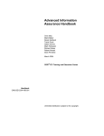
Physical Layer
The physical layer is a set of cables and interface modules that
provides a channel for communication between the nodes. A node is
a connection point onto a network, typically containing a unique
address.
IBMPC XT, AT or
compatible computer
DF1 link
RS232 Network Interface
network link
DH/DH+/DH485 link
nodes
ControlNet
link
When you connect a computer serially to your DH, DH+, DH-485,
or ControlNet link, the interface module acts as an interface between
the:
• DF1 link (RS-232 or RS-422-A)
• network link (DH, DH+, DH485, ControlNet link)
DF1 Link
A DF1 link provides:
• master-slave communication through a half-duplex protocol
• peer-to-peer communication through a full-duplex protocol
This manual provides information necessary to write your own
driver for an intelligent device on a DF1 link. See “Software
Layers,” on page 1–7, for the layers your software driver must
implement so that your intelligent device can talk to other DH,
DH+, DH485, or ControlNet nodes.
Network Link
These network links are available for peer-to-peer communication:
This link
Connects
And allows
See page
DH
•PLC2, PLC3
processors
•color graphic systems
•personal computers
•host computers
•programmable
RS232/RS422 devices
up to 64 nodes➀
1-3
up to 64 nodes
1-5
up to 32 nodes
1-6
up to 99 nodes
--------
DH+
DH485
ControlNet
➀
Publication 17706.5.16 - October 1996
•same devices as DH
•PLC5 processors
•SLC 5/04 processor
•SLC 500 processors
•color graphic systems
•personal computers
•PLC5 processors
•I/O devices
•personal computers
•operator interface devices
Using bridges (e.g., 1785KA modules), you can extend the length of your DH network to contain
up to 255 nodes.
Network Layers
1–3
DH Link
A DH link is a local area network (LAN) designed for factory-floor
applications. This link accepts 64 devices and can transmit 57.6 K
bits of data per second.
A DH link consists of a trunk cable up to 10,000 feet (3,048 meters)
long and drop cables as long as 100 feet (30.48 meters) each.
Each node is at the end of a drop cable and connects to the DH link
through a station connector (cat. no. 1770-SC). This is the only
configuration tested and supported by Allen-Bradley.
This processor
Connects to a DH link through the
PLC2 family
DH PLC2 family communication adapter module
(cat. nos. 1771KA2, KG)
PLC3
DH PLC3 family communication adapter module
(cat. nos. 1775KA,S5, SR5)
PLC5/250
Resource manager module
(cat. nos. 5130KA, RM1,RM2)
PLC5, SLC 5/04➀
DH+/DH communication module
(cat. no. 1785KA)
➀
Although a PLC5 processor does not directly connect to a DH link, it can communicate with
devices on a DH link via the 1785KA module.
A DH link implements peer-to-peer communication through a
scheme called the floating master. With this arrangement, each
node has equal access to become the master. The nodes bid for
temporary mastership based on their need to send information.
Publication 17706.5.16 - October 1996
1–4
Network Layers
Unlike a master/slave relationship, a floating master relationship
does not require the current master to poll each node to grant
permission to transmit. Therefore, it provides a more efficient
network because there is less overhead—i.e., time—per transaction.
PLC2/30 processor
personal computer
SC
= station connector; 1770SC
1771KG
modem
modem
PLC3 processor
cat. nos. 1775KA or S5
SC
PLC5/250 processor
5130RM1
RS232C link
(50 cableft. max.)
modem
modem
DH interface module
cat. nos. 1771KE, KF
SC
SC
SC
DH link
1770KF2
SC
SC
SC
1770KF2
RS232C link
(50 cableft. max.)
1785KA
DH+ link
PLC2 family processor
cat. no. 1771KA2
T60 industrial workstation running
ControlView software
Publication 17706.5.16 - October 1996
Network Layers
1–5
DH+ Link
A DH+ link is similar to a DH link, but is optimally used for smaller
networks consisting of limited nodes (about 15 maximum). A DH+
link accepts 64 devices and can transmit data at 57.6, 115.2, or
230.4K bits. (PLC-5/250, SLC, and PLC processors support 57.6
and 115.2K bits; SLC 5/04 processors support 230.4K bits; PLC-5
processors are expected to support 230.4K bits early in 1997.)
This processor
Connects to a DH+ link
PLC2
through the PLC2 Family Interface module
(cat. no. 1785KA3)
PLC3
through the I/O Scanner Communication Adapter module
(cat. nos. 1775S5,SR5)
PLC5
directly
PLC5/250
through the Resource Manager module
(cat. nos. 5130KA, RM1, RM2)
SLC 5/04➀
directly
➀
You can configure the data rate for SLC 5/04 processors.
A DH+ link implements peer-to-peer communication with a
token-passing scheme to rotate link mastership among the nodes
connected to that link.
SC
= station connector; 1770SC
personal computer
T71 with 1784KTx
PLC5 processor
PLC3 processor
cat. no. 1775S5
PLC5/250 processor
cat. no. 5130RM1
notebook computer
with 1784PCMK
1785KE
SC
DH+ link
SC
1770KF2
SLC 5/04 processor
RS232C link
(50 cableft. max.)
1785KA
SC
DH link
T53 programming
terminal with 1784KT PLC2 processor
cat. no. 1785KA3
installed
(or any other PLC2
processor)
T60 industrial
workstation with
ControlView software
Publication 17706.5.16 - October 1996
1–6
Network Layers
DH485 Link
A DH485 link is a low cost, peer-to-peer programming and
data-acquisition link for a variety of Allen-Bradley products.
DH485 topology is similar to DH and DH+ topology. You can
connect as many as 32 nodes to a DH485 link.
The DH485 link is based on the Electrical Industries Association
(EIA) Standard RS-485 Electrical Signalling Specification.
A variety of Allen-Bradley products (including SLC 500 controllers,
1784-KTX, 1747-KE, 1770-KF3, and operator interface devices) act
as token-passing masters on the DH485 link. This link also supports
a respond-only mode for low-level devices on the link, such as
Allen-Bradley bar code decoders.
A DH485 link implements peer-to-peer communication with a
token-passing scheme to rotate link mastership among the nodes
connected to that link.
T53 programming terminal with a
1784KTX card installed and running
6200 series software
PLC5 processor
DH+ link
1747AIC
SLC 5/04
channel 1 processor
1747AIC
1747AIC
SLC 500
fixed 30I/O
controller with
expansion chassis
notebook compute
with 1784PCMK
RS232/RS485
converter
1747PICÀ
SLC 5/01 processor
in 17slot modular system
channel 0
DH485 link
1747SN
SLC 5/03
processor
PanelView 550
operator terminal
DTAM Plus
operator
interface
1747AIC
1770KF3
1747AIC
remote I/O link
ÀTo connect an SLC 5/04 to a 1747PIC,
use a 9pin (male) to 25pin (female) adapter.
Publication 17706.5.16 - October 1996
to remote
I/O chassis
Network Layers
Software Layers
1–7
Your DF1 links and network links (DH, DH+, and DH485) each use
two layers of software to enable communication:
• the data-link layer
• the application layer
This figure shows how these layers fit together.
DH/DH+/DH485
RS232 interface modules
computer
PLC processor
application
application
common
application
routines
common
application
routines
RS232
data link
layer
RS232
link layer
(DF1)
link layer
(network)
DH/DH+
DH485
DH/DH+
/DH485 data
link layer
Datalink Layer
This layer controls the flow of communication over the physical link
and:
• determines the encoding of data on the physical medium
• controls who transmits data and who listens using an
arbitration protocol
• conveys data packets intact from the source node to the
destination node over the physical link
"
If your link is
Then
a DH, DH+ or DH485 link
you do not need to program this layer.
Your application programs on the network
are not involved with internode protocol,
handshaking, or control of the link.
a DF1 link between AllenBradley
interface modules
the interface modules automatically take
care of this layer. Your application
program does not have to be involved with
handshaking control.
a DF1 link between an AllenBradley
interface module and a computer
you must program this layer at your
computer.
Programming the data-link layer
You can program the data link layer using DF1 protocol.
For more information, see Chapter 3, “Using Half-duplex Protocol to
Send and Receive Messages,” or Chapter 4, “Using Full-duplex
Protocol to Send and Receive Messages.”
Publication 17706.5.16 - October 1996
1–8
Network Layers
Application Layer
This layer controls and executes the actual commands specified in
the communication between nodes. This layer is the same for both
DF1 and network links. The application layer:
• interfaces to user processes and databases
• interprets commands
• formats user data into packets
The application layer depends upon the type of node the application
is running on since it must interface to the user process and interpret
the user database.
"
Processes in the application layer
The application layer is typically organized into two types of
processes:
• senders — A sender, after receiving a signal from the user
process, sends a message and awaits a reply. It then sends the
results to the user process.
• responders — A responder waits for an incoming message from
the link. When the responder receives a message, it performs the
indicated operation on the user data base and returns a reply
message to the sender.
If your physical link is
Then
a network link
the communication modules automatically
take care of this layer.
a DF1 link between AllenBradley interface
modules
the interface modules automatically take
care of this layer. (See figure below.)
1747KE
SLC 5/02
processor
DH485 link
RS232
DF1 fullduplex
1785KE
PLC5/15
processor
DH+ link
a DF1 link between an AllenBradley
interface module and a computer
Publication 17706.5.16 - October 1996
you will need to program this layer at your
computer.
Network Layers
"
1–9
Messages
See Chapter 7, “Communication Commands,” for:
• a description of the command messages for each type of
PLC processor
• information on how to program the application layer fields of a
message packet for an asynchronous link
Message Packet Structure
All messages on a network have the same fundamental structure,
regardless of their function or destination. If you could freeze a
message packet while it is in transmission, you would see:
Bytes
protocol
data
Contents
Information used by the application and datalink layers of your software to
get the message to its destination:
•If a transaction originates from a PLC processor, the interface module
automatically fills the protocol bytes.
•If the transaction originates from a computer, your computer software
must supply the necessary protocol.
Information supplied by application program at the source and delivered to
the application program at the destination.
The following sections describe bytes that you define using the
application-layer protocol bytes in your message packet.
For a detailed description of how to use these bytes for each type of
command, see Chapter 7, “Communication Commands.”
To define this
See this page
command and reply message
1-9
message priority
1-10
delivery order of commands
1-10
types of commands
1-11
error codes
1-11
Command and Reply Message
A network transaction consists of a command and a reply.
The two parts provide extra data integrity by making sure that a
required action always returns a reply with some sort of status, either
zero status for a good reply, or non-zero status as an error code.
The application-layer protocol distinguishes a command from a
reply. The data area of a command and its corresponding reply
depend on the type of command.
Publication 17706.5.16 - October 1996
1–10
Network Layers
Message Priority
You specify the priority level for each DH command in the message
command code. The node that receives a command message must
establish the same priority level for its corresponding reply message:
This link
Classifies a message as
DH
high priority or normal priority
Priority levels of messages determine the order in which nodes transmit
messages on a DH link. In the polling process, nodes with high priority
messages will always be given priority over nodes with normal priority
messages.
DH+
normal priority
DH485
normal priority
Important:
Nodes with high priority messages are given priority
over nodes with normal priority messages throughout
the command/reply message cycle. For this reason, a
command should be given a high priority designation
only when special handling of specific data is required.
Using an excessive number of high-priority commands
defeats the purpose of this feature and could delay or
inhibit the transmission of normal priority messages.
Delivery Order of Commands
The sending node, the network, and the receiving node execute
commands based on network conditions, including—but not limited
to:
• nodes buffering commands
• retries due to noise on the network
• priority levels
If your application requires that commands be delivered in a specific
order, your logic must control the initiation of one command at a
time on the network and verify delivery before initiating additional
commands. This verification is completed by:
• a done bit or an error bit in a PLC processor
• a reply message in a computer
A done bit or a successful reply causes the next command to be
initiated. If an error bit or a reply with non-zero status is returned,
you must decide the appropriate action based on your application.
Important:
Publication 17706.5.16 - October 1996
If any node on the network initiates multiple commands
(for example, the sending node sets multiple bits at any
one time), the order in which these commands get
executed at the receiving node cannot
be guaranteed.
Network Layers
1–11
Types of Commands
From your computer on a DF1 link to a node on a DH, DH+ or
DH485 link, you can send four types of commands:
• read
• write
• diagnostic
• upload/download
For additional information on the commands you can send,
see Chapter 7, “Communication Commands.”
Error Codes
When your computer sends a command on the asynchronous link, a
status code is returned in the reply message. This code tells you the
status of the command sent from your computer. You must program
your computer to interpret this code. For more information on codes
and their meanings, see Chapter 8, “Message Packet Status Codes.”
Error codes can be generated at two places:
• the sending node
• the receiving node
For codes that are returned from the sending node:
From this node
sending node
receiving node
Error codes are generated when
•an application program used the wrong message format or issued
illegal commands.
•the sending node cannot complete a transaction due to network
problems.
an application problem exists at the receiving node. Typically, these
involve:
•the PLC processor being off line (in Program mode, for example)
or
•the command trying to access a memory area is blocked by the
interface module or user application program (i.e., the data table
location does not exist or is restricted).
Publication 17706.5.16 - October 1996
Protocol
Understanding DF1 Protocol Chapter 2
Using Halfduplex Protocols to Send and Receive
Messages Chapter 3
Using Fullduplex Protocols to Send and Receive
Messages Chapter 4
Chapter
2
Understanding DF1 Protocol
If you are connecting an interface module to a computer, you must
program the computer to understand and issue the proper protocol
character sequences. This chapter describes the DF1 protocol you
can use with your DF1-link driver for:
• peer-to-peer (two-way simultaneous) communication
• master-slave (two-way alternate) communication
This chapter includes these sections:
Section
Page
DF1 Protocol
2-2
Character Transmission
2-5
Transmission Symbols
2-6
Important:
The 1784-KT and 1784-KT2 cards connect directly to
DH+; the 1784-KR card connects directly to DH-485.
As a result, an asynchronous RS-232 interface is not
used and the information in this chapter does not apply
to software written for these cards, which use the
Standard Driver software.
Publication 17706.5.16 - October 1996
2–2
Understanding DF1 Protocol
DF1 Protocol
A link protocol is a set of programming rules for interpreting the
signals transmitted over a physical link. A protocol, such as DF1:
• carries a message, error free, from one end of the link to the other
It has no concern for the content of the message, the function of
the message, or the ultimate purpose of the message.
For example, with full-duplex DF1 protocol, it accomplishes this
by attaching a check character (BCC) or check characters (CRC)
to the end of each command and reply. The device receiving the
command or reply then verifies the BCC or CRC and returns an
ACK—if the BCC or CRC is acceptable—or an NAK—if the
BCC or CRC does not check.
• indicates failure with an error code
Internally, the link protocol must delimit messages, detect and
signal errors, retry after errors, and control message flow.
DF1 protocol is an Allen-Bradley data-link layer protocol that
combines features of subcategories D1 (data transparency) and F1
(two-way simultaneous transmission with embedded responses) of
ANSI x3.28 specification. There are two categories of DF1
protocol:
• half-duplex protocol (master-slave communication)
• full-duplex protocol (peer-to-peer communication)
Halfduplex Protocol
Half-duplex protocol is a multidrop protocol for one master and one
or more slaves. With half-duplex protocol, you can have 2 to 255
nodes simultaneously connected on a single link; this link operates
with all nodes interfaced through half-duplex modems. (For a list of
devices that can be used as masters and slaves, see page 3–2. For
more on half-duplex protocol, refer to Chapter 3, “Using Half-duplex
Protocol to Send and Receive Messages.”)
To implement half-duplex protocol, use the following
communication characteristics:
• 8 bits per character
• no parity
• 1 stop bit
Publication 17706.5.16 - October 1996
Understanding DF1 Protocol
"
2–3
Using half-duplex protocol
When you use half-duplex protocol, the intended environment is a
multidrop link with all nodes interfaced through half-duplex
modems. Unless there is only one slave directly connected to a
master, you must use a modem. Your modems must support these
signals:
• request-to-send (RTS)
• clear-to-send (CTS)
• data-carrier-detect (DCD)
• data-set-ready (DSR)
• data-terminal-ready (DTR)
If your modem does not support the DCD and DSR signals, you
must jumper DCD and DSR to DTR.
You designate one node as master to control which node has access
to the link. All other nodes are slaves, and must wait for permission
from the master before transmitting. Each slave node has a unique
node number between 0 and 254 (decimal).
The master can send and receive messages to and from each node on
the multidrop link and to and from every node on network links
connected to the multidrop link.
If the master is programmed to relay messages, then nodes on the
multidrop link can engage in virtual slave-to-slave communication.
This communication is transparent to the application.
Multiple masters are not allowed, except when one acts as a
backup to the other and does not communicate unless the primary is
shut down.
"
Slave-to-slave communication
In slave-to-slave communication, the master looks at the packet
received from the slave. If the packet is not for the master,
the master reassembles the packet as a master packet and sends the
packet to slave devices.
Publication 17706.5.16 - October 1996
2–4
Understanding DF1 Protocol
Fullduplex Protocol
Use full-duplex protocol:
• over a point-to-point link that allows two-way simultaneous
transmission
• over a multidrop link where interface modules are able to
arbitrate transmission on the link
• for high performance applications where it is necessary to get the
highest possible throughput from the available medium
If you connect an interface module to another Allen-Bradley
communication interface module, the modules automatically handle
the link arbitration. (For a list of modules that automatically handle
link arbitration, refer to page 4–1.)
"
Full-duplex dial-up modems
Full-duplex dial-up modems can be used as long as a carrier is
detected before the carrier timeout (about 10 seconds). If a carrier is
not sensed before the timeout, the module drops DTR to trigger the
modem to hang up the phone. A carrier must be sensed at least
every 10 seconds to maintain the connection.
Publication 17706.5.16 - October 1996
Understanding DF1 Protocol
Character Transmission
2–5
Allen-Bradley interface modules send data serially over the
RS-232-C/RS-422-A interface, one 10-bit byte—11-bit byte with
parity—at a time. The transmission format conforms to ANSI
X3.16, CCITT V.4, and ISO 1177 standards, with the exception that
the parity bit is retained while the data length is extended to eight
bits. Make sure that your computer conforms to this mode of
transmission. The transmission format is:
No Parity
start bit
data bit 0
data bit 1
data bit 2
data bit 3
data bit 4
data bit 5
data bit 6
data bit 7
one stop bit
With Parity
start bit
data bit 0
data bit 1
data bit 2
data bit 3
data bit 4
data bit 5
data bit 6
data bit 7
even parity bit
one stop bit
For all DH, DH+, and DH485 interface modules, you must comply
with this transmission format. For communication rates and parity
settings, refer to your module’s user manual.
Publication 17706.5.16 - October 1996
2–6
Understanding DF1 Protocol
Transmission Symbols
Both half-duplex and full-duplex protocols are character-oriented.
They use the ASCII control characters in the tables below, extended
to eight bits by adding a zero for bit 7:
Table 2.A
Halfduplex Protocol
Abbreviation
Hexadecimal Value
Binary Value
STX
02
0000 0010
SOH
01
0000 0001
ETX
03
0000 0011
EOT
04
0000 0100
ENQ
05
0000 0101
ACK
06
0000 0110
DLE
10
0001 0000
NAK
0F
0000 1111
Table 2.B
Fullduplex Protocol
Abbreviation
Hexadecimal Value
Binary Value
STX
02
0000 0010
ETX
03
0000 0011
ENQ
05
0000 0101
ACK
06
0000 0110
DLE
10
0001 0000
NAK
0F
0000 1111
(For the standard definition of these characters, refer to the ANSI
X3.4, CCITT V.3, and ISO 646 standards.)
A symbol is a sequence of one or more bytes having a specific
meaning to the link protocol. The component characters of a
symbol must be sent one after another with no other characters
between them. DF1 protocol combines the characters listed in the
tables above into control and data symbols:
• Control symbols are fixed symbols required by the DF1 protocol
to read a particular message
• Data symbols are variable symbols which contain the application
data for a particular message
Publication 17706.5.16 - October 1996
Understanding DF1 Protocol
2–7
Table 2.C
Halfduplex Transmission Symbols
Symbol
Type
Meaning
DLE SOH
control symbol
Sender symbol that indicates the start of a master
message.
DLE STX
control symbol
Sender symbol that separates the multidrop
header from the data.
DLE ETX
BCC/CRC
control symbol
Sender symbol that terminates a message.
DLE ACK
control symbol
Response symbol which signals that a message
has been successfully received.
DLE NAK
control symbol
Global link reset command only issued by the
master. Causes the slaves to cancel all messages
that are ready to transmit to the master. Typically,
the slave returns the message and an error code to
the originator.
DLE ENQ
control symbol
Sender symbol, issued only by the master, that
starts a poll command.
DLE EOT
BCC
control symbol
Response symbol used by slaves as a response to
a poll when they have no messages to send.
STN
data symbol
Station number of the slave node on your
halfduplex link.
APP DATA
data symbol
Single characters having values 000F and 11FF.
Includes data from application layer including user
programs and common application routines. A data
1016 is sent as 10 10 (DLE DLE).
DLE DLE
data symbol
Represents the data value or STN value
of 1016. See APP DATA.
Publication 17706.5.16 - October 1996
2–8
Understanding DF1 Protocol
Table 2.D
Fullduplex Transmission Symbols
Publication 17706.5.16 - October 1996
Symbol
Type
Meaning
DLE STX
control symbol
Sender symbol that indicates the start of a message
frame.
DLE ETX
BCC/CRC
control symbol
Sender symbol that terminates a message frame.
DLE ACK
control symbol
Response symbol which signals that a message
frame has been successfully received.
DLE NAK
control symbol
Response symbol which signals that a message
frame was not received successfully.
DLE ENQ
control symbol
Sender symbol that requests retransmission of a
response symbol from the receiver.
APP DATA
data symbol
Single character data values between 000F and
11FF. Includes data from application layer including
user programs and common application routines.
A data 1016 is sent as 10 10 (DLE DLE).
DLE DLE
data symbol
Represents the data value of 1016.
Chapter
3
Using Halfduplex Protocols to
Send and Receive Messages
In half-duplex protocol, devices share the same data circuits,
therefore only one device can “talk” at a time. Half-duplex protocol
can be likened to a one-lane bridge: each car must wait its turn to
cross the bridge. (To compare half-duplex to full-duplex protocol,
refer to Chapter 4, “Using Full-duplex Protocols to Send and
Receive Messages.”)
Read this chapter to help learn how to use half-duplex protocol to
send and receive messages. It contains these sections:
Section
Page
Halfduplex Protocol Message Transmission
3-2
Transmitter and Receiver Message Transfer
3-3
Halfduplex Protocol Environment
3-3
Message Characteristics
3-7
Master Polling Responsibilities
3-7
Slave Transceiver Actions
3-9
Halfduplex Protocol Diagrams
3-11
Publication 17706.5.16 - October 1996
3–2
Using Half-duplex Protocols to Send and Receive Messages
Halfduplex Protocol Message Half-duplex protocol:
Transmission
• is a multidrop protocol for one master and one or more slaves
• provides a lower data throughput than full-duplex
• allows communication with each node on the multidrop link
• allows communication with nodes on links connected to the
multidrop link
If the master is programmed to relay messages, then nodes on the
multidrop can engage in virtual slave-to-slave transfers. Half-duplex
protocol operates on a multidrop link with all nodes interfaced
through half-duplex modems. There may be from 2 to 255 nodes
simultaneously connected to a single link.
In half-duplex mode, one node is designated as master and it
controls which node has access to the link. All other nodes are
called slaves and must wait for permission from the master before
transmitting. Allen-Bradley devices with master and slave
capabilities include:
Devices with master capability
Devices with slave capability
•SLC 5/03 and 5/04 (on channel 0)À
•1747KE
•1771KGM DH SCADA Master module
•1770KF2, KF3, KFC
•5130RM1, RM2, KA (channel 1)
•1775KA (via modem port)
•5130RM2
•1785KE
•a userprogrammed intelligent device
•1771KE, KF, KG
•a personal computer running ControlView
software
•PLC5/11 5/20, 5/30, 5/40, 5/60,
PLC5/80 (on channel 0)
•personal computer running
WINtelligentt LINXt software
•PLC5/11 5/20, 5/30, 5/40, 5/60,
PLC5/80 (on channel 0)
•personal computer running RSLINXt
•SLC 5/03 and 5/04 (on channel 0)
•5130RM1, RM2, KA (channel 1)
•personal computer running
WINtelligentt LINXt software
•personal computer running RSLINXt
À
SLC 5/03 and 5/04 processors (OS302 and OS401, respectively) now support halfduplex DF1
masters.
With half-duplex protocol, you can use a:
• two-circuit system – master sends and slaves receive on one
circuit, slaves send and master receives on the other
• one-circuit system – master and slaves send and receive on the
same circuit
Publication 17706.5.16 - October 1996
Using Half-duplex Protocols to Send and Receive Messages
Transmitter and Receiver
Message Transfer
3–3
Each node on a multidrop link contains a software routine to transmit
and receive messages. DH and DH+ interface modules already
contain a slave transceiver routine, so they can be configured to
function as slave nodes in half-duplex mode.
Instead of a single routine, you can program separate transmitter and
receiver routines. However, in this chapter, we assume you are using
a single routine. The master and slave transmitter/receivers are
illustrated in the figure below:
source
packet
OK
packet
sink
to other slaves
master transceiver
OK
physical link
packet
OK
slave transceiver
packet
OK
source
sink
(The “source” and “sink” are defined in the next section,
“Half-duplex Protocol Environment.”
Halfduplex Protocol
Environment
To define the environment of the protocol, the transceiver:
• needs to know where to get the message it sends, the message
source. We assume the message source:
– supplies one message at a time upon request from the
transceiver
– requires notification of the success or failure of the transfer
before supplying the next message
• must have a means of disposing of messages it receives, the
message sink
When the transceiver has received a message successfully, it attempts
to give it to the message sink. If the message sink is full,
the transceiver will receive an indication that the sink is full.
Publication 17706.5.16 - October 1996
3–4
Using Half-duplex Protocols to Send and Receive Messages
The following program describes the actions of the transceiver in
detail:
TRANSCEIVER is defined
variables
LAST-HEADER is 4 bytes copied out of the last good message
BCC is an 8-bit block check accumulator
LAST-HEADER = invalid
loop
reset parity error flag
GET-CODE
if it’s a DLE SOH then
begin
GET-CODE
if it’s a data code and it matches the station number or it
is 255 (the broadcast address) then
begin
BCC = the data code
GET-CODE
if it’s a DLE STX then
begin
RESPONSE = GETMESSAGE
if RESPONSE is ACK then
begin
if message header is different from
last and sink is not full
begin
save new HEADER
try to send message to sink
end
if this is not a broadcast message
and sink was not full then
begin
turn on RTS
wait for CTS
send DLE ACK
turn off RTS
end
end
end
end
end
else if it’s a DLE ENQ then
begin
GET-CODE (the station number)
GET-CHAR (the BCC)
check the station number and the BCC, and if they’re OK then
begin
if there is a message left over from the last time and
the transmit counter is exceeded then
throw the message away and send an error code to the
message source
if there is no message then
try to get one from the message source
turn on RTS
wait for CTS
if there is still no message then send a DLE EOT
else SEND the message
turn off RTS
end
end
else if it’s a DLE ACK then
send a success code to the message source and discard the
message
else if it’s a DLE NAK then
while the message source can supply a message
begin
get a message from the message source
discard the message
send an error code to the message source
end
end
Publication 17706.5.16 - October 1996
Using Half-duplex Protocols to Send and Receive Messages
3–5
GETMESSAGE is defined as
GET-CODE
while it is data code
begin
if buffer is not overflowed put data in buffer
GET-CODE
end
if it is a control code and it is an ETX then
begin
if parity error flag is set then return a NAK
if BCC is not zero then return a NAK
if message is too small then return a NAK
if message is too large then return a NAK
return an ACK
end
else end
GET-CODE is defined as
loop
variable
GET-CHAR
if char is not a DLE
begin
add char to BCC
return the char and a data flag
end
else
begin
GET-CHAR
if char is a DLE
begin
add char to BCC
return a DLE and a data flag
end
else if char is an ETX
begin
GET-CHAR
add char to BCC
return ETX with a control flag
end
else return char with a control flag
end
end
end
GETCHAR is defined as
an implementationdependent function that returns one byte of data
from the link interface hardware
SEND (Message) is defined as
begin
BCC = 0
send DLE STX
for every byte in the message do
begin
subtract the byte from the BCC
send the corresponding data code
end
send DLE ETX BCC
end
Publication 17706.5.16 - October 1996
3–6
Using Half-duplex Protocols to Send and Receive Messages
The following flowchart shows the software logic for implementing
half-duplex protocol from the master node’s point of view:
XCVR
Yes
Does master
have message
to send?
No
Select node
Send poll
Start timeout
Receive
DLE
EOT?
No
Receive
message?
No
Yes
Node
in active
list?
Yes
Yes
No
Active
node?
Duplicate
message?
No
Send message to
application layer
Add node to
active list
Get message from
application layer
3
timeouts
this poll?
Send message
Yes
Start timeout
Yes
Received
DLE
ACK?
No
3
timeouts
this
message?
No
Publication 17706.5.16 - October 1996
Yes
Tell application
layer of failure
Add node to
inactive list
No
Yes
Yes
No
Message
OK?
Send DLE ACK
No
Yes
Send DLE ACK
8VLQJ +DOIGXSOH[ 3URWRFROV WR 6HQG DQG 5HFHLYH 0HVVDJHV
0HVVDJH &KDUDFWHULVWLFV
ï
,GHDOO\ WKH GDWDOLQN OD\HU SURWRFRO LV QRW FRQFHUQHG ZLWK WKH FRQWHQW
RU IRUP RI WKH PHVVDJHV LW LV WUDQVIHUULQJ +RZHYHU KDOIGXSOH[
SURWRFRO SODFHV WKH IROORZLQJ UHVWULFWLRQV RQ WKH PHVVDJHV WKDW DUH
VXEPLWWHG WR LW IRU WUDQVIHU
0LQLPXP VL]H RI OLQNOD\HU GDWD LV E\WHV
0D[LPXP VL]H RI OLQNOD\HU GDWD GHSHQGV RQ WKH DSSOLFDWLRQOD\HU
FRPPDQG
6RPH SURWRFRO LPSOHPHQWDWLRQV UHTXLUH WKDW WKH ILUVW E\WH RI D
PHVVDJH PDWFK WKH QRGH DGGUHVV WKXV UHFHLYHUV LJQRUH PHVVDJHV
WKDW GR QRW FRQWDLQ WKH FRUUHFW DGGUHVV 7KLV ILOWHULQJ FDQ
RSWLRQDOO\ EH SHUIRUPHG E\ WKH PHVVDJH VLQN
$V SDUW RI WKH GXSOLFDWH PHVVDJH GHWHFWLRQ DOJRULWKP WKH UHFHLYHU
FKHFNV WKH VRXUFH 65& FRPPDQG &0' DQG WUDQVDFWLRQ
716 ILHOGV RI HDFK PHVVDJH 7KHUH PXVW EH D GLIIHUHQFH LQ DW
OHDVW RQH RI WKHVH E\WHV EHWZHHQ D PHVVDJH DQG WKH SUHYLRXV
PHVVDJH 2WKHUZLVH WKH PHVVDJH LV FODVVLILHG DV D UHWUDQVPLVVLRQ
RI WKH SUHYLRXV PHVVDJH )RU PRUH LQIRUPDWLRQ RQ WKHVH ILHOGV
VHH SDJHV 12 7$*12 7$* DQG 12 7$*
0DVWHU 3ROOLQJ
5HVSRQVLELOLWLHV
7KH PDVWHU SROOLQJ DOJRULWKP YDULHV GHSHQGLQJ RQ WKH H[SHFWHG IORZ
RI WUDIILF WKURXJK WKH V\VWHP $ VLPSOH PDVWHU FRQWLQXRXVO\ SROOV
HDFK VODYH LQ ´URXQGURELQµ IDVKLRQ ,I D PHVVDJH LV UHFHLYHG LW LV
KDQGOHG WKHQ WKH QH[W QRGH LV SROOHG ,Q DGGLWLRQ WR JHQHUDO
UHVSRQVLELOLWLHV PDVWHUV DUH UHVSRQVLEOH IRU
GHWHFWLQJ GXSOLFDWHV
SROOLQJ LQDFWLYH VODYHV
UHOLHYLQJ IXOO VLQNV
XVLQJ VLPSOLILHG QHWZRUN OD\HU
VODYHWRVODYH PHVVDJH UHOD\LQJ
'XSOLFDWH 'HWHFWLRQ
'XSOLFDWH GHWHFWLRQ LQIRUPDWLRQ PXVW EH NHSW IRU HDFK QRGH XQOHVV
WKH PDVWHU SROOV HDFK QRGH UHSHDWHGO\ XQWLO LW LV HPSW\ EHIRUH
SURFHHGLQJ WR WKH QH[W 7KHQ GXSOLFDWH GHWHFWLRQ LQIRUPDWLRQ RQO\
QHHGV WR EH NHSW IRU WKH FXUUHQW QRGH
,QDFWLYH 6ODYH 3ROOLQJ
,I D VODYH IDLOV WR UHVSRQG WR D SROO WKH PDVWHU UHPRYHV WKH VODYH
IURP WKH OLVW RI DFWLYH VODYHV 7R VDYH WLPH WKH PDVWHU SROOV WKH
DFWLYH VODYHV RQ D UHJXODU EDVLV DQG SROOV WKH LQDFWLYH VODYHV
RFFDVLRQDOO\ WR VHH LI WKH\ UHVSRQG :KHQ DQ LQDFWLYH VODYH GRHV QRW
UHVSRQG WR D SROO LW LV SXW EDFN LQWR WKH DFWLYH VODYH OLVW
3XEOLFDWLRQ ï 2FWREHU ï
8VLQJ +DOIGXSOH[ 3URWRFROV WR 6HQG DQG 5HFHLYH 0HVVDJHV
)XOO 6LQNV
:KHQ D QRGH WLPHV RXW WR D PHVVDJH FRPPDQG SROO WKH QRGH WR VHH
LI LW UHVSRQGV ,I LW UHVSRQGV WR WKH SROO ZLWK D '/( (27 EXW
FRQVLVWHQWO\ IDLOV WR $&. D PHVVDJH LWV VLQN LV SUREDEO\ IXOO
<RX PXVW ZDLW IRU WKH EXIIHUV WR FOHDU EHIRUH VHQGLQJ DQRWKHU
PHVVDJH
%XIIHUIXOO FRQGLWLRQ
6RPH GHYLFHV KROG GDWD LQGHILQLWHO\ 7R JHW WKH GDWD DQG UHOLHYH WKH
EXIIHUIXOO FRQGLWLRQ \RX PXVW SROO WKH GHYLFH
:KHQ D QRGH·V PHVVDJH VRXUFH DQG VLQN VKDUH D FRPPRQ PHPRU\
SRRO DQ DEXQGDQFH RI PHVVDJHV LQ WKH PHVVDJH VRXUFH PD\ FDXVH D
PHVVDJH VLQN IXOO LQGLFDWLRQ ,Q WKLV FDVH WKH PDVWHU FDQ SROO WKH
QRGH WR UHFHLYH PHVVDJHV DQG PDNH PHPRU\ DYDLODEOH :DLWLQJ IRU
WKH PHPRU\ WR FOHDU RQ LWV RZQ PD\ QRW ZRUN RQ DOO GHYLFHV WKH RQO\
ZD\ WR IUHH PHPRU\ LV WR KDYH WKH PDVWHU SROO WKH QRGH
6LPSOLILHG 1HWZRUN /D\HU
7R DOORZ SHHUWRSHHU FRPPXQLFDWLRQ RQ WKH PXOWLGURS \RXU PDVWHU
PXVW XVH D VLPSOLILHG QHWZRUN OD\HU 7KLV QHWZRUN OD\HU UHVLGHV MXVW
DERYH WKH GDWDOLQN OD\HU DQG SHUIRUPV URXWLQJ DQG UHOD\LQJ RI
PHVVDJHV )RU PRUH RQ WKH QHWZRUN OD\HUV UHIHU WR &KDSWHU ´1HWZRUN /D\HUVµ
3XEOLFDWLRQ ï 2FWREHU 8VLQJ +DOIGXSOH[ 3URWRFROV WR 6HQG DQG 5HFHLYH 0HVVDJHV
6ODYH 7UDQVFHLYHU $FWLRQV
ï
6LQFH LQSXW VHQW WR WKH WUDQVFHLYHU FDQ RIWHQ EH DIIHFWHG E\ QRLVH
IURP WKH SK\VLFDO ZRUOG WKH WUDQVFHLYHU PXVW EH FDSDEOH RI
UHVSRQGLQJ WR PDQ\ DGYHUVH VLWXDWLRQV VXFK DV
7KH PHVVDJH VLQN FDQ EH IXOO OHDYLQJ QRZKHUH WR SXW D PHVVDJH
$ PHVVDJH FDQ FRQWDLQ D SDULW\ HUURU
7KH %&&&5& FDQ EH LQYDOLG
7KH '/( 62+ '/( 67; RU '/( (7; %&&&5& PD\ EH
PLVVLQJ
7KH PHVVDJH FDQ EH WRR ORQJ RU WRR VKRUW
$ VSXULRXV FRQWURO RU GDWD V\PERO FDQ RFFXU RXWVLGH D PHVVDJH
$ VSXULRXV FRQWURO V\PERO FDQ RFFXU LQVLGH D PHVVDJH
7KH '/( $&. UHVSRQVH FDQ EH ORVW FDXVLQJ WKH WUDQVPLWWHU WR
VHQG D GXSOLFDWH FRS\ RI D PHVVDJH WKDW KDV DOUHDG\ EHHQ SDVVHG
WR WKH PHVVDJH VLQN
:DLWV IRU PHVVDJH
7KH VODYH LV DOZD\V LQ D SDVVLYH PRGH XQWLO LW UHFHLYHV D PHVVDJH
:KLOH ZDLWLQJ IRU D PHVVDJH DQ\ PHVVDJH RWKHU WKDQ WKH '/( 62+
RU '/( (14 LV LJQRUHG ,Q D VLQJOH FLUFXLW V\VWHP WKH VODYHV PXVW
EH DEOH WR VDIHO\ LJQRUH HYHU\WKLQJ VHQW E\ RWKHU VODYHV
5HFHLYHV PHVVDJH
,I D '/( 62+ LV UHFHLYHG WKH %&&&5& DQG WKH PHVVDJH EXIIHU DUH
UHVHW 7KH QH[W V\PERO UHFHLYHG PXVW EH D GDWD V\PERO DQG PXVW
HTXDO WKH QRGH DGGUHVV RU LI WKH QRGH FDQ UHFHLYH EURDGFDVW
PHVVDJHV
,I WKH QRGH DGGUHVV DQG WKH V\PERO
7KHQ
GR QRW PDWFK
WKH QRGH LJQRUHV WKH UHVW RI WKH PHVVDJH
DQG FRQWLQXHV ZDLWLQJ IRU WKH VWDUW RI WKH
PHVVDJH
PDWFK
LW LV DGGHG WR WKH %&&&5&
7KH QH[W V\PERO LV UHFHLYHG DQG PXVW PDWFK WKH '/( 67; LI WKH
V\PERO DGGUHVV GRHVQ·W PDWFK WKH QRGH LJQRUHV WKH UHVW RI WKH
PHVVDJH DQG WKH V\PERO VWDUWV EXLOGLQJ D PHVVDJH
%XLOGV D PHVVDJH
:KLOH EXLOGLQJ D PHVVDJH DOO GDWD V\PEROV DUH VWRUHG LQ WKH PHVVDJH
EXIIHU DQG DGGHG WR WKH DFFXPXODWHG %&&&5& 7KH VODYH VHWV DQ
HUURU IODJ WR LQGLFDWH WKH RFFXUUHQFH RI D SDULW\ EXIIHU RYHUUXQ
PHVVDJH IUDPLQJ RU PRGHP KDQGVKDNLQJ HUURU
3XEOLFDWLRQ ï 2FWREHU ï
8VLQJ +DOIGXSOH[ 3URWRFROV WR 6HQG DQG 5HFHLYH 0HVVDJHV
9HULILHV '/( (7; %&&&5&
3HUIRUPV GXSOLFDWH GHWHFWLRQ
5HFHLYHV D SROO
,I DQ\ FRQWURO V\PERO RWKHU WKDQ D '/( (7; %&&&5& LV UHFHLYHG
DW WKH HQG RI WKH SDFNHW WKH PHVVDJH LV GLVFDUGHG DQG DOO LQSXW LV
LJQRUHG XQWLO WKH QH[W '/( 62+ RU '/( (14 LV UHFHLYHG :KHQ WKH
'/( (7; %&&&5& LV UHFHLYHG WKH HUURU IODJ WKH %&&&5& WKH
PHVVDJH VL]H DQG WKH DGGUHVV RSWLRQDOO\ DUH DOO YHULILHG
,I '/( (7; %&&&5& FRQWHQW LV
7KHQ WKH
LQFRUUHFW
PHVVDJH LV LJQRUHG
FRUUHFW
VODYH EHJLQV WKH GXSOLFDWH PHVVDJH GHWHFWLRQ
SURFHVV
7KH VODYH FRPSDUHV WKH 65& &0' DQG ERWK 716 E\WHV WR WKH
FRUUHVSRQGLQJ E\WHV RI WKH SUHYLRXV PHVVDJH
,I WKHVH E\WHV DUH
7KHQ WKH VODYH
WKH VDPH
GLVFDUGV WKH FXUUHQW PHVVDJH DQG VHQGV D '/( $&.
GLIIHUHQW
WHVWV WKH VWDWH RI WKH PHVVDJH VLQN
,I WKH PHVVDJH VLQN LV IXOO WKH WUDQVFHLYHU GLVFDUGV WKH FXUUHQW
PHVVDJH DQG GRHV QRW UHVSRQG
,I WKH PHVVDJH VLQN LV QRW IXOO WKH WUDQVFHLYHU
IRUZDUGV WKH FXUUHQW OLQN OHYHO GDWD WR WKH PHVVDJH VLQN
NHHSV D FRS\ RI WKH ILUVW IRXU E\WHV RI WKH FXUUHQW OLQNOHYHO GDWD
IRU GXSOLFDWH PHVVDJH GHWHFWLRQ
VHQGV D '/( $&.
,I ZKLOH ZDLWLQJ IRU D PHVVDJH D SROO '/( (14 671 %&& LV
UHFHLYHG WKH WUDQVFHLYHU DFFHSWV WKH QH[W WZR FKDUDFWHUV 7KH ODVW
FKDUDFWHU LV D %&& DQG LV QRW E\WH VWXIIHG ,I WKH VWDWLRQ DGGUHVV GRHV
QRW PDWFK RU WKHUH LV DQ HUURU WKH SROO LV LJQRUHG ,I WKH SROO LV
DFFHSWHG WKHUH DUH WKUHH SRVVLEOH VLWXDWLRQV
7KH WUDQVFHLYHU FRXOG VWLOO EH KROGLQJ D PHVVDJH WKDW LW KDG
WUDQVPLWWHG SUHYLRXVO\ EXW KDG QRW EHHQ $&.HG 7KHUH LV D OLPLW
RQ WKH QXPEHU RI WLPHV HDFK UHSO\ PHVVDJH FDQ EH VHQW
,I WKLV OLPLW LV
7KHQ
H[FHHGHG
ZKHQ WKH SROO LV UHFHLYHG WKH UHSO\ PHVVDJH LV UHWXUQHG WR WKH
PHVVDJH VRXUFH ZLWK DQ HUURU LQGLFDWLRQ DQG WKH WUDQVFHLYHU WULHV
WR VHQG WKH QH[W PHVVDJH IURP WKH PHVVDJH VRXUFH
QRW H[FHHGHG
WKH UHVSRQVH WR WKH SROO LV WR UHVHQG WKH FXUUHQW UHSO\ PHVVDJH
,I QR PHVVDJH LV FXUUHQWO\ EHLQJ KHOG WKH WUDQVFHLYHU WULHV WR JHW
RQH IURP WKH PHVVDJH VRXUFH
3XEOLFDWLRQ ï 2FWREHU ,I
7KHQ
D PHVVDJH LV DYDLODEOH
WKH WUDQVFHLYHU LQLWLDOL]HV LWV UHWU\ FRXQWHU DQG WUDQVPLWV LW
LQ UHVSRQVH WR WKH SROO
QR PHVVDJH LV DYDLODEOH
WKH UHVSRQVH WR D SROO LV WR WUDQVPLW D '/( (27
8VLQJ +DOIGXSOH[ 3URWRFROV WR 6HQG DQG 5HFHLYH 0HVVDJHV
ï
7UDQVPLWV D PHVVDJH
:KHQ D PHVVDJH LV WUDQVPLWWHG DIWHU UHFHLYLQJ D SROO LWV IRUPDW LV
LGHQWLFDO WR D IXOOGXSOH[ PHVVDJH SDFNHW $IWHU VHQGLQJ D PHVVDJH
WKH WUDQVFHLYHU KROGV WKH PHVVDJH XQWLO D '/( $&. LV UHFHLYHG RU
WKH QXPEHU RI WLPHV WKH PHVVDJH KDV EHHQ SROOHG H[FHHGV WKH OLPLW
5HFHLYHV '/( $&.
:KHQ D '/( $&. LV UHFHLYHG WKH PHVVDJH FXUUHQWO\ KHOG LV
GLVFDUGHG DQG WKH PHVVDJH VRXUFH LV QRWLILHG RI D VXFFHVVIXO GHOLYHU\
:KHQ WKH QH[W SROO LV UHFHLYHG WKH QH[W PHVVDJH DYDLODEOH IURP WKH
PHVVDJH VRXUFH LV VHQW RU D '/( (27
5HFHLYHV '/( 1$.
:KHQ D '/( 1$. LV UHFHLYHG WKH WUDQVFHLYHU WDNHV PHVVDJHV IURP
WKH VRXUFH XQWLO LW LV HPSW\ (DFK PHVVDJH LV GLVFDUGHG ZLWK DQ HUURU
FRGH VHQW EDFN WR WKH PHVVDJH VRXUFH 7KLV FDQ EH XVHG E\ WKH
PDVWHU WR FOHDU XS WKH PHVVDJH VRXUFH EXIIHUV RI DOO VODYHV DIWHU WKH
PDVWHU KDV EHHQ GRZQ
+DOI'XSOH[ 3URWRFRO
'LDJUDPV
7KH IROORZLQJ ILJXUHV VKRZ HYHQWV WKDW RFFXU RQ YDULRXV LQWHUIDFHV
/LQNOD\HU GDWD E\WHV DUH UHSUHVHQWHG E\ ´[[[[µ DQG FRUUXSWHG GDWD
LV UHSUHVHQWHG E\ ´"""µ
7KHVH ILJXUHV VKRZ WKH VWHSV WKDW RFFXU RQ WKH GDWDOLQN OD\HU ZKHQ D
VLQJOH FRPPDQG PHVVDJH SDFNHW LV VHQW WKH\ GR QRW VKRZ WKH VWHSV
LQYROYHG ZKHQ WKH UHFHLYLQJ QRGH UHWXUQV D UHSO\ PHVVDJH SDFNHW
)RU WKLV WUDQVIHU
6HH SDJH
QRUPDO PHVVDJH WUDQVIHU
ï
PHVVDJH WUDQVIHU ZLWK LQYDOLG %&&
ï
PHVVDJH WUDQVIHU ZLWK DFN GHVWUR\HG
ï
SROO ZLWK QR PHVVDJH DYDLODEOH
ï
SROO ZLWK PHVVDJH UHWXUQHG
ï
GXSOLFDWH PHVVDJH WUDQVPLVVLRQ
ï
PHVVDJH VLQN IXOO FDVH ï
PHVVDJH VLQN IXOO FDVH ï
3XEOLFDWLRQ ï 2FWREHU ï
8VLQJ +DOIGXSOH[ 3URWRFROV WR 6HQG DQG 5HFHLYH 0HVVDJHV
1RUPDO 0HVVDJH 7UDQVIHU
,Q WKLV WUDQVIHU
GDWD E\WHV DUH VHQW IURP WKH VRXUFH WR WKH PDVWHU DQG WUDQVPLWWHG
WR D VODYH
WKH VLQN VHQGV D ´QRW IXOOµ PHVVDJH
WKH GDWD LV VHQW WR WKH VLQN DQG D '/( $&. LV VHQW WR WKH PDVWHU
WKH PDVWHU WHOOV WKH VRXUFH WKDW WKH PHVVDJH ZDV GHOLYHUHG
6RXUFH
6LQN
0DVWHU
[[[[
/LQN
6RXUFH
6LQN
6ODYH
'/( 62+ 671 '/( 67; [[[[ '/( (7; %&&&5&
QRW IXOO
[[[[
'/( $&.
2.
VRPHWLPH ODWHU '/( (14 671 %&&
SROO
'/( 67; [[[[ '/( (7; %&&&5&
'/( $&.
0HVVDJH 7UDQVIHU ZLWK ,QYDOLG %&&&5&
,Q WKLV WUDQVIHU
WKH PDVWHU VHQGV D PHVVDJH ZLWK DQ LQYDOLG %&&&5&
WKH PDVWHU UHFHLYHV QR $&. DQG WLPHV RXW
WKH PDVWHU UHWUDQVPLWV ZLWK D YDOLG %&&&5& DQG SURFHHGV ZLWK
D QRUPDO PHVVDJH WUDQVIHU
6RXUFH
6LQN
0DVWHU
[[[[
/LQN
6ODYH
6RXUFH
6LQN
'/( 62+ 671 '/( 67; """ '/( (7; %&&&5&
WLPHRXW
'/( 62+ 671 '/( 67; [[[[ '/( (7; %&&&5&
QRW IXOO
'/( $&.
2.
3XEOLFDWLRQ ï 2FWREHU [[[[
8VLQJ +DOIGXSOH[ 3URWRFROV WR 6HQG DQG 5HFHLYH 0HVVDJHV
ï
0HVVDJH 7UDQVIHU ZLWK $&. 'HVWUR\HG
,Q WKLV WUDQVIHU
WKH PDVWHU VHQGV D PHVVDJH
WKH VODYH DFFHSWV WKH PHVVDJH DQG UHWXUQV D '/( $&. EXW WKH
'/( $&. LV GHVWUR\HG
WKH PDVWHU UHWUDQVPLWV DQG SURFHHGV ZLWK D QRUPDO PHVVDJH
WUDQVIHU
,I GXSOLFDWH GHWHFW LV HQDEOHG WKH GXSOLFDWH PHVVDJH LV GLVFDUGHG
6RXUFH
6LQN
0DVWHU
[[[[
/LQN
6ODYH
6RXUFH
6LQN
'/( 62+ 671 '/( 67; [[[[ '/( (7; %&&&5&
QRW IXOO
[[[[
'/("""&.
WLPHRXW
'/( 62+ 671 '/( 67; [[[[ '/( (7; %&&&5&
'/( $&.
2.
3ROO ZLWK 1R 0HVVDJH $YDLODEOH
,Q WKLV WUDQVIHU
WKH PDVWHU SROOV WKH VODYH IRU D PHVVDJH
WKH VODYH KDV QR PHVVDJH
WKH VODYH UHWXUQV D '/( (27
6RXUFH
6LQN
QRW IXOO
0DVWHU
/LQN
6ODYH
6RXUFH
6LQN
'/( (14 671 %&&
QR PHVVDJH
'/( (27
3XEOLFDWLRQ ï 2FWREHU ï
8VLQJ +DOIGXSOH[ 3URWRFROV WR 6HQG DQG 5HFHLYH 0HVVDJHV
3ROO ZLWK 0HVVDJH 5HWXUQHG
,Q WKLV WUDQVIHU
WKH PDVWHU SROOV IRU D PHVVDJH DQG WKH VODYH UHWXUQV D PHVVDJH
ZLWK IDXOW\ GDWD
VLQFH LW GLG QRW UHFHLYH D '/( $&. RQ LWV ILUVW DWWHPSW WKH VODYH
UHWUDQVPLWV WKH VDPH PHVVDJH
WKH PDVWHU UHVSRQGV ZLWK D '/( $&.
6RXUFH
6LQN
QRW IXOO
0DVWHU
/LQN
6ODYH
6RXUFH
6LQN
'/( (14 671 %&&
[[[[
'/( 67; [["""[[ '/( (7; %&&&5&
'/( (14 671 %&&
'/( 67; [[[[ '/( (7; %&&&5&
VDPH PHVVDJH
[[[[
'/( $&.
3XEOLFDWLRQ ï 2FWREHU 2.
8VLQJ +DOIGXSOH[ 3URWRFROV WR 6HQG DQG 5HFHLYH 0HVVDJHV
ï
'XSOLFDWH 0HVVDJH 7UDQVPLVVLRQ
,Q WKLV WUDQVIHU
D VODYH GRHV QRW UHFHLYH D '/( $&. IURP WKH PDVWHU DIWHU WKH
PDVWHU UHFHLYHV WKH VODYH·V PHVVDJH
ZKHQ WKH PDVWHU SROOV WKH VODYH DJDLQ WKH VODYH VHQGV WKH VDPH
PHVVDJH
WKH PDVWHU VHQGV D '/( $&. EXW GLVFDUGV WKH GXSOLFDWH PHVVDJH
7R LPSOHPHQW GXSOLFDWH PHVVDJH GHWHFWLRQ WKH PDVWHU PXVW HLWKHU
SROO D QRGH UHSHDWHGO\ ZLWKRXW SROOLQJ DQ\ RWKHU QRGH XQWLO LW
UHFHLYHV D '/( (27
NHHS D UHFRUG LI HDFK QRGH LV SROOHG RQO\ RQFH SHU F\FOH RI WKH OLQNOD\HU GDWD E\WHV RI WKH ODVW PHVVDJH SDFNHW VHQW E\ HDFK VODYH
QRGH VLQFH RWKHU QRGHV PD\ WUDQVIHU PHVVDJHV EHIRUH D QRGH
UHWUDQVPLWV 7KH PDVWHU PXVW EXIIHU WKH HQWLUH UHSO\ XQWLO LW FDQ
WUDQVPLW WKH UHSO\ WR WKH VODYH
6RXUFH
6LQN
0DVWHU
/LQN
6RXUFH
6LQN
6ODYH
QRW IXOO
'/( (14 671 %&&
[[[[
'/( 67; [[[[ '/( (7; %&&&5&
[[[[
'/ """ &.
VRPHWLPH ODWHU '/( (14 671 %&&
'/( 67; [[[[ '/( (7; %&&
&5&
'/( $&.
2.
GLVFDUG UHWUDQVPLVVLRQ
3XEOLFDWLRQ ï 2FWREHU ï
8VLQJ +DOIGXSOH[ 3URWRFROV WR 6HQG DQG 5HFHLYH 0HVVDJHV
0HVVDJH 6LQN )XOO &DVH ,Q WKLV WUDQVIHU WKH VODYH·V PHVVDJH VLQN LV IXOO ,I D VODYH GRHV QRW
UHVSRQG WR D FRPPDQG WKHQ WKLV PLJKW LQGLFDWH WKDW WKH VODYH·V
EXIIHUV DUH IXOO ,I WKH VODYH·V EXIIHUV DUH IXOO WKHQ D SROO E\ WKH
PDVWHU UHVXOWV LQ WKH VODYH WUDQVPLWWLQJ D UHSO\ RWKHU WKDQ '/( (27
6RXUFH
6LQN
0DVWHU
[[[[
/LQN
6ODYH
6RXUFH
6LQN
'/( 62+ 671 '/( 67; [[[[ '/( (7; %&&&5&
IXOO
WLPHRXW
QRW IXOO
VRPHWLPH ODWHU
'/( 62+ 671 '/( 67; [[[[ '/( (7; %&&&5&
QRW IXOO
[[[[
'/( $&.
2.
3XEOLFDWLRQ ï 2FWREHU 8VLQJ +DOIGXSOH[ 3URWRFROV WR 6HQG DQG 5HFHLYH 0HVVDJHV
ï
0HVVDJH 6LQN )XOO &DVH ,Q WKLV WUDQVIHU WKH VODYH·V PHVVDJH VRXUFH DQG PHVVDJH VLQN VKDUH
WKH VDPH PHPRU\ SRRO DV ZLWK WKH .* 7KH PHVVDJH VLQN LV
IXOO EHFDXVH WKHUH DUH WRR PDQ\ PHVVDJHV LQ WKH PHVVDJH VRXUFH
7R FOHDU WKH PHVVDJH VLQN WKH PDVWHU PXVW ILUVW UHFHLYH PHVVDJHV
IURP WKH VODYH·V PHVVDJH VRXUFH 2WKHUZLVH WKH VODYH·V VLQN ZLOO
UHPDLQ IXOO
6RXUFH
6LQN
0DVWHU
[[[[
/LQN
6ODYH
6RXUFH
6LQN
'/( 62+ 671 '/( 67; [[[[ '/( (7; %&&&5&
IXOO
WLPHRXW
QRW IXOO
'/( (14 671 %&&
IXOO
'/( 67; [[[[ '/( (7; %&&&5&
[[[[
'/( $&.
'/( 62+ 671 '/( 67; [[[[ '/( (7; %&&&5&
'/( $&.
2.
QRW IXOO
VRPHWLPH ODWHU
'/( (14 671 %&&
'/( 67; [[[[ '/( (7; %&&
QRW IXOO
QR
PHVVDJHV
WR VHQG
3XEOLFDWLRQ ï 2FWREHU Chapter
4
Using Fullduplex Protocol to
Send and Receive Messages
In full-duplex protocol, devices share the same data circuits, and
both devices can “talk” at the same time. Full-duplex protocol can
be likened to a two-lane bridge: traffic can travel in both directions
at one time. (To compare full-duplex to half-duplex protocol, refer
to Chapter 3, “Using Half-duplex Protocols to Send and Receive
Messages.”)
Read this chapter to help learn how to use full-duplex protocol to
send and receive messages. It contains these sections:
Section
"
Page
Fullduplex Protocol Message Transmission
4-2
Fullduplex Protocol Environment
4-3
Message Characteristics
4-4
Transmitter and Receiver Message Transfer
4-4
Fullduplex Protocol Diagrams
4-10
Link arbitration
You can use these Allen-Bradley interface modules to automatically
handle the link arbitration:
•1747KE
•1771KE
•1775KA (via modem port)
•1770KF2
•1771KF
•1785KE
•1770KF3
•1771KG
•5130RM1 (channel one)
•1770KFC
•5130KA
•5130RM2
Publication 17706.5.16 - October 1996
4–2
Using Full-duplex Protocol to Send and Receive Messages
Fullduplex Protocol
Message Transmission
With full-duplex protocol, a link uses two physical circuits for
two-way simultaneous message transmission (command or reply
message packets). These two physical circuits provide
communication on four logical paths:
Figure 4.1
Data paths for twoway simultaneous operation
path 1
receiver B
transmitter A
path 2
circuit 1
circuit 2
path 3
receiver A
transmitter B
path 4
•On the first circuit, transmitter A sends messages to receiver B (path 1) and receiver A sends response
control symbols (DLE ACK, DLE NAK) to transmitter B (path 3).
•On the second circuit, transmitter B sends messages to receiver A (path 4) and receiver B sends
response control symbols (DLE ACK, DLE NAK) to transmitter A (path 2).
•All message and symbols on the first circuit are traveling in the same direction (node A to node B) and all
messages and symbols on the second circuit are traveling in the opposite direction (B to A).
Publication 17706.5.16 - October 1996
Using Full-duplex Protocol to Send and Receive Messages
4–3
Figure 4.2
Software implementation of data paths
Paths 1, 2, 3, and 4
Transmitter A
Receiver B
Path 1
Software
Multiplexer
Path 2
Physical Circuit BA
Software
Separator
Path 4
Path 1
Path 2
Physical Circuit AB
Software
Separator
Software
Multiplexer
Path 3
Path 4
Path 3
Transmitter B
Receiver A
Paths 1 (a message symbol sent from node A to node B)
Transmitter A
Receiver B
Path 1
Software
Multiplexer
Physical Circuit
Path 1
Software
Separator
•To implement four logical paths with two physical circuits, a software multiplexer is needed to combine the message symbols with
the response symbols going in the same direction.
•At the other end of the link, a software separator divides the message symbols from the response symbols.
The internal software sends the message symbols to the appropriate receiver, and the response symbols to the appropriate
transmitter.
•Although message symbols and response symbols on the same circuit operate independently of each other,
there is some interaction.
•For example, a message on physical circuit AB will be delayed if a response symbol from receiver A is inserted in a stream of
message symbols from transmitter A (embedded response).
•Also, any hardware problems that affect message symbols traveling over a circuit will also affect response symbols
on the same circuit.
Fullduplex Protocol
Environment
To define the environment of the protocol:
• the transmitter needs to know where to get the message it sends,
the message source. We assume the message source:
– supplies one message at a time upon request from the
transmitter
– requires notification of the success or failure of the transfer
before supplying the next message
• the receiver must have a means of disposing of messages,
the message sink
If the
Then the
message source is empty
transmitter waits in an inactive state until a
message is available
receiver has received a message
successfully
receiver attempts to give it to the message
sink. If the message sink is full, the
receiver must be notified
Publication 17706.5.16 - October 1996
4–4
Using Full-duplex Protocol to Send and Receive Messages
Figure 4.3 shows the protocol environment for message symbols
from transmitter A to receiver B (path 1) and response codes from
receiver B to transmitter A (path 2).
Figure 4.3
Protocol Environment
Packet
Source
Path 1
Transmitter A
Packet
Receiver B
Sink
Path 2
Packet Status
Message Characteristics
Sink Full
Ideally, the data-link-layer protocol is not concerned with the content
or form of the message packet (link-layer data) it is transferring.
However, full-duplex protocol places the following restrictions on
link-layer data submitted to it for transfer:
• minimum size of valid link-layer data is 6 bytes
• maximum size of valid link-layer data depends on the
application-layer command
• some protocol implementations (e.g., point-to-point links to a
1771-KG module) require that the first byte of the link-layer data
match the node address
The receiver ignores messages that do not contain the correct
address.
• as part of the duplicate message detection algorithm, the receiver
compares the second, third, fifth, and sixth bytes of the link-layer
data with the same bytes in the previous message
If there is no difference between the sets of bytes, the message is
classified as a re-transmission of the previous message. You can
set some Allen-Bradley interface modules so that they do not
implement duplicate-message detection.
Transmitter and Receiver
Message Transfer
Publication 17706.5.16 - October 1996
In full-duplex protocol, messages are sent from the source (part of
software that supplies message packet) through a transmitter
(device that sends data) and then a receiver (device that receives
data) to the sink (part of the software that accepts the received data):
For
See page
structured text on how the transmitter operates
4-5
a flowchart of how the transmitter operates
4-6
structured text on how the receiver operates
4-7
a flowchart of how the receiver operates
4-9
Using Full-duplex Protocol to Send and Receive Messages
4–5
How the Transmitter Operates
The following program describes the actions of the transmitter:
Whenever the message source can supply a message packet and the
transmitter is not busy, it sends a frame on the link to the destination
address. It then starts a timeout, and waits for a response.
When this response is
received from the receiving
address
The message packet
DLE ACK
has been successfully transferred.
After signaling the message
source that the message packet
was successfully transmitted, the
transmitter proceeds with the next
message packet.
DLE NAK
is retransmitted. The transmitter
restarts the timeout and waits
again for a response. If it receives
a DLE ACK, the transmitter starts
a timeout.
This can be repeated several
times. You can set a limit to the
number of times a message can
be retransmitted for each module.
If this limit is exceeded, the
message source is informed of the
failure and the transmitter
proceeds with the next message.
If the timeout expires before a response is received, the transmitter sends
a DLE ENQ to request a retransmission of the last response. It restarts
the timeout and waits for a response.
You can also set a limit to the number of timeouts that are allowed per
message. If the enquiry (ENQ) limit is exceeded, the transmitter signals
the message source that the transmission has failed, and the transmitter
proceeds to the next message.
There are three responses defined: DLE ACK, DLE NAK, DLE ENQ,
If the transmitter receives an different response, the transmitter ignores it.
TRANSMITTER is defined as
loop
Message=GET-MESSAGE-TO-SEND
Status=TRANSFER(Message)
SIGNAL-RESULTS(Status)
end loop
loop
WAIT for response on path 2 or timeout.
if received DLE ACK then return SUCCESS
else if received DLE NAK then
if nak-limit is exceeded then return FAILURE
else
begin
count NAK re-tries;
SEND-MESSAGE(message);
start timeout
end
else if timeout
if enq-limit is exceeded then return FAILURE
else
begin
count ENQ re-tries;
send DLE ENQ on path 1;
start timeout
end
end loop
SEND (message) is defined as
begin
BCC = 0
send DLE STX on path 1
for every byte in the message do
begin
add the byte to the BCC;
send the corresponding data symbol
on
path 1
end
send DLE ETX BCC on path 1
end
GET-MESSAGE-TO-SEND
This is an operating-system-dependent interface
routine that waits and allows the rest of the
system to run until the message source has supplied
a message to be sent.
SIGNAL-RESULTS
This is an implementation-dependent routine that
tells the message source of the results of the
attempted message transfer.
WAIT
This is an operating-system-dependent routine
that waits for any of several events to occur
while allowing other parts of the system to run.
TRANSFER (Message) is defined as
initialize nak-limit and enq-limit
SEND(Message)
start timeout
Publication 17706.5.16 - October 1996
4–6
Using Full-duplex Protocol to Send and Receive Messages
The following flowcharts the software logic for implementing the
transmitter:
T
retransmit same message
message frame
DLE
STX
Data
DLE
ETX
BCC/CRC
Field
timeout loop
Received
DLE
ACK?
Yes
Legend:
T
= Ready to transmit next message
P
= Recovery procedure
*
= Default values used by the module
No
Received
DLE
NAK?
No
Timed
out?
Yes
Yes
T
3* NAKs
received
for this
message?
Yes
P
Yes
3* ENQ
sent?
No
No
DLE
Important:
Publication 17706.5.16 - October 1996
No
ENQ
Depending on network-link traffic and saturation level,
you may need to wait for a reply from the remote node
before transmitting the next message. Implement an
option that allows users to choose the maximum amount
of outstanding messages that can exist at one time;
we suggest a selectable range of one to three messages.
Using Full-duplex Protocol to Send and Receive Messages
4–7
How the Receiver Operates
The receiver must be capable of responding to adverse situations.
Some of the problems that can occur are:
• the message sink is full, so the receiver has nowhere to put
a message
• a message can contain a parity error
• the BCC or CRC can be invalid
• the DLE STX or DLE ETX BCC/CRC may be missing
• the message is too long or too short
• a false control or data symbol occurs outside a message
• a false control symbol occurs inside a message
• the DLE ACK response is lost, causing the transmitter to send a
duplicate copy of a message already passed to the message sink
Publication 17706.5.16 - October 1996
4–8
Using Full-duplex Protocol to Send and Receive Messages
The following program describes the actions of the receiver in detail.
The receiver keeps a record of the last response sent to
the transmitter. The value of this response is either DLE
ACK or DLE NAK. It is initialized to DLE NAK. When a
DLE ENQ (enquiry) is received from the transmitter, the
receiver sends the value of the last response.
The receiver ignores all input until a DLE STX or DLE ENQ
is received. If anything other than a DLE STX or DLE ENQ
is received on path one, the receiver sets the last response
variable to NAK.
When this symbol is received
from the transmitter
Then the
DLE ENQ
last response is sent
and the receiver
continues waiting for
input.
DLE ACK
BCC/CRC and the
message buffer are
reset, and the receiver
starts building a reply
message.
While building a reply message, all data symbols are
stored in the message buffer and added to the BCC/CRC.
If the buffer overflows, the receiver continues summing the
BCC/CRC, but the data is discarded.
If a parity, overrun, framing, or modem handshaking error is
detected, it is recorded .
If a control symbol other than DLE STX or DLE ETX is
received, the message is aborted and a DLE NAK is sent
to the transmitter. When DLE STX or DLE ETX is received,
the error flag, the BCC/CRC, the message size, and the
address (optionally) are all checked. If any of the tests fail,
a DLE NAK is sent.
GETCHAR is defined as an implementationdependant
function that returns one byte of data from the link
interface hardware
Publication 17706.5.16 - October 1996
RECEIVER is defined as
variables
LAST-HEADER is 4 bytes copied out of the last good message
RESPONSE is the value of the last ACK or NAK sent
BCC is an 8-bit block check accumulator
LAST-HEADER = invalid
LAST RESPONSE = NAK
loop
reset parity error flag
GET-SYMBOL
if DLE STX then
begin
BCC = 0
GET-SYMBOL
while it is a data symbol
begin
if buffer is not overflowed put
data in buffer
GET-SYMBOL
end
if the control symbol is not a DLE ETX then send DLE
NAK
else if error flag is set then send DLE NAK
else if BCC is not zero then send DLE NAK
else if message is too small then send DLE NAK
else if message is too large then send DLE NAK
else if header is same as last message send a DLE ACK
else if message sink is full send DLE NAK
else
begin
send message to message sink
send a DLE ACK
save a last header
end
end
else if DLE ENQ then send LAST-RESPONSE
else LAST-RESPONSE = NAK
end loop
GET-SYMBOL is defined as
loop
GET-CHAR
if char is not DLE
begin
add char to BCC
return the char and data flag
end
else
begin
GET-CHAR
if char is a DLE
begin
add char to BCC
return DLE and data flag
end
else if char is an ACK or NAK send it to the transmitter
else if char is an ETX
begin
GET-CHAR
add char to BCC
return ETX with a control flag
end
else return char with a control flag
end
end loop
Using Full-duplex Protocol to Send and Receive Messages
4–9
The following flowchart is the software logic for implementing the
receiver.
RCVE
LAST = NAK
Received
DLE
ENQ?
Yes
No
No
Received
message?
Yes
BCC/
CRC
OK?
No
LAST = NAK
Yes
LAST = ACK
Send DLE LAST
Publication 17706.5.16 - October 1996
4–10
Using Full-duplex Protocol to Send and Receive Messages
Fullduplex Protocol
Diagrams
These transfer diagrams show events that occur on various
interfaces. Time is represented as increasing from the top of the
diagram to the bottom. Link-layer data bytes are represented by
“xxxx” and corrupted data by “???”.
For this diagram
See page
normal message transfer
4-10
message transfer with NAK
4-11
message transfer with timeout & ENQ
4-12
message transfer with retransmission
4-13
message transfer with message sink full
4-14
message transfer with NAK on reply
4-15
message transfer with timeout and ENQ for the reply
4-16
message transfer with message source full on the reply
4-17
Normal Message Transfer
In this transfer:
• the transmitter sends the data to the receiver
• the sink sends a “not full” message
• the receiver sends the data to the sink and sends a DLE ACK to
the transmitter
• the transmitter tells the source that the data was delivered
• reply is successfully returned
Source
Transmitter
Link
Receiver
Sink
command
xxxx
DLE STX xxxx DLE ETX BCC/CRC
DLE ACK
OK
reply
not full
xxxx
(sometime later ...)
not full
DLE STX xxxx DLE ETX BCC/CRC
xxxx
DLE ACK
Publication 17706.5.16 - October 1996
OK
Using Full-duplex Protocol to Send and Receive Messages
4–11
Message Transfer with NAK
In this transfer:
• the transmitter sends corrupted data to the receiver and the
receiver responds with a DLE NAK
• the transmitter retransmits and the transmission is successful
• the receiver sends a DLE ACK to the transmitter
• reply is successfully returned
Source
Transmitter
command
xxxx
Link
Receiver
Sink
DLE STX x???x DLE ETX BCC/CRC
DLE NAK
DLE STX xxxx DLE ETX BCC/CRC
not full
xxxx
DLE ACK
OK
reply
(sometime later ...)
not full
DLE STX xxxx DLE ETX BCC/CRC
xxxx
DLE ACK
OK
Publication 17706.5.16 - October 1996
4–12
Using Full-duplex Protocol to Send and Receive Messages
Message Transfer with Timeout and ENQ
In this transfer:
• the receiver receives a transmission, but sends back a
DLE ACK that is corrupted
• the transmitter times out waiting for the DLE ACK and sends a
DLE ENQ
• the receiver sends back a DLE ACK
• a reply is successfully returned
Source
Transmitter
command
xxxx
Link
DLE STX xxxx DLE ETX BCC/CRC
DL???CK
Receiver
Sink
not full
xxxx
(timeout)
DLE ENQ
DLE ACK
OK
reply
(sometime later ...)
not full
xxxx
Publication 17706.5.16 - October 1996
DLE STX xxxx DLE ETX BCC/CRC
DLE ACK
OK
Using Full-duplex Protocol to Send and Receive Messages
4–13
Message Transfer with ReTransmission
In this transfer:
• noise destroys the DLE ACK while also producing invalid
characters at the receiver
• because of the invalid characters, the receiver changes its last
response variable to a DLE NAK
• since the DLE ACK was destroyed, the transmitter sends a DLE
ENQ (enquiry), and the receiver returns the DLE NAK
• the transmitter retransmits the message and the receiver sends an
ACK
• the receiver discards the duplicate message (if duplicate message
detection is enabled on your module)
• reply is successfully returned
Source
Transmitter
command
xxxx
Link
Receiver
DLE STX xxxx DLE ETX BCC/CRC
not full
xxxx
DL???CK
(timeout)
Sink
???
(timeout)
DLE ENQ
DLE NAK
DLE STX xxxx DLE ETX BCC/CRC
DLE ACK
OK
(duplicate message)
(sometime later ...)
reply
not full
xxxx
DLE STX xxxx DLE ETX BCC/CRC
DLE ACK
OK
In this transfer, the receiver has no way of knowing that the DLE
ACK it sent to the transmitter was destroyed. If the transmitter’s
ACK timeout is large enough, it is possible that the reply
(i.e., DLE STX xxxx DLE ETX BCC/CRC) comes back before the
transmitter sends the DLE ENQ. Therefore, the reply comes in
before the DLE ACK is received by the transmitter.
Publication 17706.5.16 - October 1996
4–14
Using Full-duplex Protocol to Send and Receive Messages
Message Transfer with Message Sink Full
In this transfer:
• the transmitter sends a message but the message sink is full,
so the receiver sends back a DLE NAK
• the transmitter retransmits and the sink is no longer full,
so the receiver returns a DLE ACK
• a reply is successfully returned
Source
Transmitter
command
xxxx
Link
DLE STX xxxx DLE ETX BCC/CRC
Receiver
Sink
Full
DLE NAK
DLE STX xxxx DLE ETX BCC/CRC
Full
DLE NAK
DLE STX xxxx DLE ETX BCC/CRC
DLE ACK
OK
reply
not full
xxxx
(sometime later ...)
DLE STX xxxx DLE ETX BCC/CRC
not full
xxxx
Publication 17706.5.16 - October 1996
DLE ACK
OK
Using Full-duplex Protocol to Send and Receive Messages
4–15
Message Transfer with NAK on Reply
In this transfer:
• the message is successfully transmitted on the network
• the reply is corrupted and the transmitter responds with a DLE
NAK
• the reply is sent again and is successful
Source
Transmitter
command
xxxx
Link
Receiver
DLE STX xxxx DLE ETX BCC/CRC
DLE ACK
Sink
not full
xxxx
OK
(sometime later ...)
reply
DLE STX x??x DLE ETX BCC/CRC
DLE NAK
DLE STX xxxx DLE ETX BCC/CRC
not full
xxxx
DLE ACK
OK
Publication 17706.5.16 - October 1996
4–16
Using Full-duplex Protocol to Send and Receive Messages
Message Transfer with Timeout and ENQ for the Reply
In this transfer:
• the message is successfully transmitted on the network
• the receiver sends a reply from the network but the transmitter
sends back a DLE ACK that is corrupted
• the receiver times out waiting for the DLE ACK and sends a DLE
ENQ
• the transmitter sends back a DLE ACK
Source
Transmitter
command
xxxx
Link
DLE STX xxxx DLE ETX BCC/CRC
DLE ACK
Receiver
Sink
not full
xxxx
OK
(sometime later ...)
reply
DLE STX xxxx DLE ETX BCC/CRC
not full
xxxx
DL???CK
(Timeout)
DLE ENQ
DLE ACK
Publication 17706.5.16 - October 1996
OK
Using Full-duplex Protocol to Send and Receive Messages
4–17
Message Transfer with Message Source Full on the Reply
In this transfer:
• the message is successfully transmitted on the network
• the receiver sends a reply but the message source is full,
so the transmitter sends back a DLE NAK
• the receiver retransmits and the source is no longer full,
so the transmitter returns a DLE ACK
Source
Transmitter
command
xxxx
Link
Receiver
DLE STX xxxx DLE ETX BCC/CRC
DLE ACK
Sink
not full
xxxx
OK
(sometime later ...)
reply
Full
DLE STX xxxx DLE ETX BCC/CRC
DLE NAK
DLE STX xxxx DLE ETX BCC/CRC
not full
xxxx
DLE ACK
OK
Publication 17706.5.16 - October 1996
Message Packets
Datalink Layer Message Frames Chapter 5
Application Layer Message Packets Chapter 6
Communication Commands Chapter 7
Message Packet Status Codes (STS and EXT STS)
Chapter 8
Chapter
5
Datalink Layer Message
Frames
In the data-link layer of a message frame:
• half-duplex protocol uses three types of message transmission
• full-duplex protocol implements its message fields at different
network layers
• at the end of each polling and message frame, there is a one-byte
BCC field or a two-byte CRC field
Read this chapter to help learn the fields that your computer uses in
the data-link layer of a message frame. It contains these sections:
Section
Page
Halfduplex Protocol Message Frames
5-2
Fullduplex Protocol Message Frames
5-3
BCC and CRC Fields
5-4
Publication 17706.5.16 - October 1996
5–2
Data-link Layer Message Frames
Halfduplex Protocol
Message Frames
Half-duplex protocol uses three types of transmissions:
• polling frame
• master message frame
• slave message frame
The master node transmits both polling frames and master message
frames, and slave nodes transmit slave message frames.
The following figure illustrates the formats of these frames.
The slave message frame has the same format as the full-duplex
message frame. The master message frame is the same as the slave
message frame except that it is prefixed with DLE SOH and an
address to specify a slave station address (STN).
Important:
Even if you set your module to use CRC, when you
send a polling frame, it uses a single BCC byte.
Polling Frame
DLE ENQ
STN
BCC
Master Message Frame
From common application routines
DLE
SOH STN
DLE
STX
DST
SRC CMD STS
TNS
Data
(command data)
DLE
ETX
BCC/
CRC
TNS
Data
(command data)
DLE
ETX
BCC/
CRC
Slave Message Frame
DLE
STX
DST
SRC CMD STS
From common application routines
The BCC field contains the 2's complement of the 8bit sum (module256 arithmetic sum) of the slave station address
(STN) and all the data bytes in the frame. For polling frames, the BCC is simply the 2's complement of STN. The BCC
does not include any other message frame symbols or response symbols.
Publication 17706.5.16 - October 1996
Data-link Layer Message Frames
Fullduplex Protocol
Message Frames
Full-duplex protocol implements different message frames,
depending on the network layer. This figure shows the format of a
message frame for full-duplex protocol and the layer at which each
portion is implemented:
From user application program
DST
From common application routines
DST
SRC
DLE
STX
Datalink layer frame
5–3
CMD
STS
CMD
STS
data from
application layers
command data
TNS
DLE
data
(from application layer)
ETX
BCC/CRC
field
The BCC/CRC field contains the 2's complement of the 8bit sum (module256 arithmetic sum) of all
application layer data bytes between the DLE STX and the DLE ETX BCC. It does not include any
response symbols. You can use the BCC/CRC field for one of the following types of error checking:
• block check character (BCC)
• 16bit cyclic redundancy check (CRC16)
Publication 17706.5.16 - October 1996
5–4
Data-link Layer Message Frames
BCC and CRC Fields
At the end of each polling frame and each message frame, there is
a one-byte BCC (block check character) field, or a two byte CRC
(cyclic redundancy check) field. You select BCC or CRC through
switch settings or software configuration. Either field allows you to
verify the accuracy of each message frame transmission:
• The BCC algorithm provides a medium level of data security:
– it cannot detect transposition of bytes during transmission
of a frame
– it cannot detect the insertion or deletion of the value zero
within a frame
• The CRC field provides a higher level of data security than BCC
but is more difficult to implement
BCC Field
We’ve included both half- and full-duplex BCC examples:
Half-duplex protocol example
If the master node wants to send the hexadecimal data symbols 08, 09, 06, 00, 10, 04, and
03 to slave node 2016 (40 octal), the master message symbols are:
10 01 20 10 02 08 09 06 00 10 10 04 03 10 03 B2
STN DLE STX APP DATA (DLE DLE)
DLE ETX BCC
The sum of the STN and application layer data bytes in this message frame is 4E16.
The BCC is the 2's complement of this sum, or B216. This is shown in the following binary
calculation:
0100 1110 = sum (4E16)
1011 0001 = 1's complement
+1
1011 0010 2's complement (B216 = BCC)
To transmit the STN or data value 10 hex, you must use the data symbol DLE DLE.
You must also use the data symbol DLE DLE if your STN value is 10. Only one of these
DLE bytes, however, is included in the BCC sum.
For example, to transmit the data values 08, 09, 06, 00, 10, 04, and 03 (hex), a slave node
uses the following message symbols:
10
DLE
02
STX
08 09 06 00 10 10 04 03
APP DATA (DLE DLE)
10 03
DLE EXT
D2
BCC
In this case, the sum of the data bytes is 2E hex because only one DLE byte is included in
the BCC. The BCC (2's complement) of 2E16 is D216.
Publication 17706.5.16 - October 1996
Data-link Layer Message Frames
5–5
Full-duplex protocol example
If a message frame contained the data 08. 09, 06, 00, 02,04, and 03 (decimal),
the message symbols are:
10
DLE
02
STX
08 09 06 00 02 04 03
APP DATA
10 03
DLE ETX
E0
BCC
The sum of the application data bytes in this message frame is 32 decimal or 20 hex.
The BCC is the 2's complement of this sum, or E0 hex. This is shown in the following
binary calculation:
0010 0000 20 16
1101 1111 1's compliment
+1
1110 0000 2's compliment (E0 hex)
To quickly determine a BCC value, add up the hex values of the application layer bytes.
If the total is greater than 100 hex, drop the most significant digit. Then, subtract the result
from 100 hex. This gives you the BCC. For example, if the sum of the application layer
bytes is 20 hex, then:
10016
-2016
____
E016
Important:
10
DLE
02
STX
To transmit the value 10 hex, you must use the data symbol DLE DLE.
However, only one of these DLE data bytes is included in the BCC sum.
For example, to transmit the values 08, 09, 06, 00, 10, 04, and 03 hex, use
the following message symbols:
08 09 06 00 10 10 04 03
APP DATA (DLE DLE)
10 03
DLE EXT
D2
BCC
In this case, the sum of the application layer data bytes is 2E hex because only one DLE
byte is included in the BCC. So the BCC is D216. This is sometimes referred to as
doublestuffing" DLEs.
Important:
If your BBC check sum is 10 hex, send it as “10” and
not “10 10.” That is, a BCC is not treated like data.
Publication 17706.5.16 - October 1996
5–6
Data-link Layer Message Frames
CRC Field
For these protocols
You calculate the CRC value➀
fullduplex
using the value of the linklayer data bytes and the ETX byte.
halfduplex
•for master messages using the value of the linklayer data
bytes and the STN, STX and ETX bytes➁
•for slave messages using the value of the linklayer data bytes
and the ETX byte
➀ The polynomial for a CRC value is:
X16 + X15 + X2 + X0.
➁ Do not add in the associated DLE for STX and ETX values.
Important:
To transmit the data value of 1016, you must use the
data symbol DLE DLE. However, only one of these
DLE bytes is included in the CRC value.
Embedded responses are not included in the CRC value.
The following explains the transmission of the CRC value:
1. At the start of a message frame, the transmitter clears a 16-bit
register used for the CRC value.
2. As a byte is transmitted, it is exclusive-ORed (least-significant bit
to the right) with the right eight bits of the CRC register.
3. The result is placed in the right eight bits of the CRC register.
4. The CRC register is then shifted right eight times by inserting 0s
on the left. Each time a 1 is shifted out on the right, the CRC
register is exclusive-ORed with this 16-bit constant:
1010 0000 0000 0001
5. As each additional byte is transmitted, it is included in the value
in the register the same way.
6. After the ETX value is transmitted, the value in the CRC register
is transmitted (right bit first). The receiver also calculates the
CRC value and compares it to the received CRC value to verify
the accuracy of the data received.
Publication 17706.5.16 - October 1996
Data-link Layer Message Frames
5–7
The full-duplex and half-duplex slave and master protocol examples
below provide you with procedures for determining the CRC-16
value.
Full-duplex and half-duplex slave protocol
data_byte = all linklayer data, ETX
CLEAR CRC_REGISTER
FOR each data_byte
GET data_byte
XOR (data_byte, right eight bits of CRC_REGISTER)
PLACE RESULT in right eight bits of CRC_REGISTER)
DO 8 times (on CRC register_
Shift bit right, shift in 0 at left
IF bit shifted = 1
XOR (CONSTANT, CRC_REGISTER)
PLACE RESULT in CRC_REGISTER
END IF
END DO
END FOR
TRANSMIT CRC_REGISTER as 2byte CRC field (low byte, high byte)
Half-duplex master protocol
data_byte = STN, STX, all linklayer data, ETX
CLEAR CRC_REGISTER
For each data_byte
GET data_byte
XOR (data_byte, right 8 bits of CRC_REGISTER)
PLACE RESULT in right 8 bits of CRC_REGISTER
DO 8 times
Shift bit right, shift in 0 at left
IF bit shifted = 1
XOR (CONSTANT, CRC_REGISTER)
PLACE RESULT in CRC_REGISTER
END IF
END DO
END FOR
TRANSMIT CRC_REGISTER as 2 byte CRC field
Below is an actual frame that you can use to validate your CRC
routine:
Use this frame to validate the CRC
10
02
07
11
41
00
53
B9
00 00 00 00 00 00 00 00 00 00 00 00 10
03
6B 4C
Publication 17706.5.16 - October 1996
Chapter
6
Application Layer Message
Packets
Read this chapter to help learn about the application layer for your
asynchronous driver and the fields that your computer uses in the
application layer of a message packet. It contains these sections:
Section
Page
How Your Application Program Sends and Receives Messages
6-2
Message Packet Format
6-3
Publication 17706.5.16 - October 1996
6–2
Application Layer Message Packets
How Your Application
Program Sends and
Receives Messages
There are two types of application programs:
• command initiators
• command executors
This application program
Sends
command initiator
command messages - specify which command function
to execute at a particular remote node
Each command message requires one reply message.
The command initiator must check for error codes and,
depending on the type of error, retransmit the message or
notify the user.
The command initiator should also use a timer to be aware
of lost reply messages (due to noise or other factors).
If the time limit expires before the initiator receives the
reply, the initiator can retransmit or notify the user.
command executor
reply messages - responsible for interpreting and
executing the command message.
The executor must issue a reply message for each
command it receives. If the executor cannot execute a
command, it must send the appropriate error code.
Internally, Allen-Bradley asynchronous interface modules use a
routing subroutine and a message queue. When the module receives
a message over its asynchronous link, it puts the message in its
queue. The routing subroutine then takes the message from the
queue and transmits it over the DH, DH+, or DH485 network.
The module also queues messages received from the network.
The routing subroutine takes these messages and retransmits them
over the asynchronous link.
If this layer
Cannot deliver a
command message
application
reply message
datalink
Publication 17706.5.16 - October 1996
message over the
asynchronous link
It should
generate a reply message with the
appropriate error code and send the reply to
the initiator.
destroy the reply without notification to the
command executor.
return an error message to the command
initiator.
Application Layer Message Packets
Message Packet Format
6–3
Most devices send and receive messages using this message
packet format:
Command
DST
SRC CMD
STS
Commandspecific
data packet
TNS
FNC
Reply
read
write
SRC DST
CMD
STS
TNS
SRC DST
CMD
STS
TNS
ADDR
SIZE DATA
Commandspecific
data packet
The bytes are shown from left to right in the order they are transmitted across the link.
Field
Contents
See
DST
SRC
FNC
CMD
destination node for the message
source node of the message
function code
command code
ADDR
address of memory location (2 bytes)
page 6-8
STS
EXT STS
status code
extended status code
page 6-6
6 6
SIZE
number of bytes to be transferred
page 6-8
TNS
transaction number (2 bytes)
page 6-7
DATA
data values being transferred by the message
The number of data bytes in a message depends on
the command or function being executed.
Chapter 7
page 6-4
6 4
6 5
page 6-5
The combination of SRC, CMD, and TNS bytes uniquely identifies
every message packet. One of these fields in the current message
must be different than the corresponding field in the last message
received by a command executor. If all fields are the same, the
message is ignored and is considered to be a duplicate. If the
receiving module has the “ignore duplicate messages” option
enabled, the message will be ignored.
Publication 17706.5.16 - October 1996
6–4
Application Layer Message Packets
DST and SRC
Form the DST and SRC bytes of a reply message by interchanging
the DST and SRC bytes of the corresponding command message:
Command
Reply
Byte
DST
(destination)
SRC
(source)
DST
SRC
SRC
DST
Contents
Value supplied by
Value range
receiving message
application layer
sending message
data link layer
•0 to 376 (octal) for DF1
•0 to 376 (octal) for DH
•0 to 77 (octal) for DH+
•0 to 31 (decimal ) for DH485
When sending messages from asynchronous devices, special
consideration must be given to the SRC byte:
When sending a message from an
asynchronous device connected
Set the SRC byte
to the network➀
= 0 (the module will set the byte to its own
node number)
directly to a 1771KG
10 (octal)
➀
Publication 17706.5.16 - October 1996
If you connect to channel 0 of a PLC5/11, 5/20, 5/30, 5/40, 5/60 or 5/80 processor and you
send a PLC2 unprotected write, protected write, protected bit write, or unprotected bit write, what
you put into the SRC byte is very important. This determines the compatibility file. This means
that the value of the SRC byte specifies the data table file number that is written to the PLC5
processor. The source byte will not be overwritten by channel 0. For SLC 500 processors, the
compatibility file is always 9.
Application Layer Message Packets
6–5
CMD and FNC
These bytes work together to define the activity that is to be
performed by the command message at the destination node.
Values for these bytes are supplied by the application layer.
The message format depends on the CMD and FNC values.
CMD byte
Bit:
7
0
6
Command
or Reply
always = 0
command message = 0
reply message = 1
5
4
3 2
Priority
0
Command
always = 0
1 0
command code
normal priority = 0
high priority= 1➀
➀ High priority only applies to DH links. It does not apply to DH+, DH485, or DHII links.
This byte
CMD
(command)
FNC
(function)
Defines the
And has these values
command type
specific function under that command type
see table that begins on
page 7-2
Example code
PLC2 command enter download mode
send = 00000111 (07 hex)
reply = 01000111 (47 hex)
highpriority send (DH only) = 00100111 27 hex
highpriority reply (DH only) = 01100111 (67 hex)
Publication 17706.5.16 - October 1996
6–6
Application Layer Message Packets
STS and EXT STS
These bytes work together to indicate the status of the message
transmission.
This byte
STS
(status)
Four high bits
of STS byte all
= 1 (F0 hex)?
Yes
EXT STS byte
Has this value
command
The application program sets = 0.
= 0 when the command has executed with no
error.
= one of the status codes listed in Chapter 8,
Message Packet Status Codes (STS, EXT
STS)." This byte will also 0 if an error
occurs.
reply
EXT STS➀
(extended status)
➀
In this message
reply
EXT STS is part of the message only if STS = F0.
STS byte
7 6
5 4
3 2
1 0
No
no EXT STS byte
Application layer uses these bits (and in some cases the EXT STS byte),
to report remote errors errors that occur when the command executor
at the destination node tries to execute the command message).
"
Link layer uses these bits to report local errors errors that occur
when the link layer attempts to transmit a message across the link.
STS and EXT STS error codes
For more information on STS and EXT STS error codes,
see Chapter 8, “Message Packet Status Codes (STS, EXT STS).”
Publication 17706.5.16 - October 1996
Application Layer Message Packets
6–7
TNS
The TNS (transaction) bytes contain a unique 16-bit transaction
identifier. Generate this number by maintaining a 16-bit counter.
Increment the counter each time your command initiator (application
program) creates a new message, and store the counter value in the
two TNS bytes of the new message. In a multi-tasking environment,
you must use only one TNS counter, and the procedure to read and
increment the TNS must be indivisible.
command
reply
TNS
Command executor copies the TNS field of the command message into
the TNS field of the corresponding reply message.
TNS
Command initiator checks TNS value of reply and matches it to one of its
command messages. The low byte (least significant bits) of the TNS value
is transmitted before the high byte (most significant bits).
For command messages
transmitted by
Values are assigned by
a PLC
the interface module assigns the TNS values.
computer node
your application level software. The software must
assign a unique 16bit transaction number.
Important:
Do not change the TNS value in a reply message.
If you change this value, the command initiator cannot
match its command to the corresponding reply message.
Publication 17706.5.16 - October 1996
6–8
Application Layer Message Packets
ADDR
The ADDR (address) bytes contain the byte address of a memory
location in the command executor where the command is to begin
executing, except in SLC 500 processors, where the ADDR byte is
interpreted as the word address.
In SLC 5/02, SLC 5/03, and SLC 5/04 processors, the CIF
Addressing Mode bit, S:2/8, can be set to a one to change the
interpretation of the ADDR byte to the byte address, so that it is
compatible with other PLC processors. For example, if the
command is to read data from the command executor, ADDR
specifies the address of the first byte of data to be read.
ADDR
contains the low (least significant) byte of the address
"
contains the high byte of the address
Sending commands to PLC-3, PLC-5, and SLC 500 processors
In some instances, when sending commands from the basic
command set to a PLC-3, PLC-5, or PLC-5/250 processor, or to an
SLC 500 processor, you must create special files to accept the data.
Important:
The ADDR field specifies a byte address, not a word
address as in PLC data tables. Chapter 13, “PLC
Addressing,” explains how to convert PLC word
addresses to byte addresses. Also, if you use the
“native” read and write commands in PLC-3, PLC-5, or
SLC 500 processors, the address is not a byte address; it
is a logical binary, logical ASCII, or SLC address with
multiple address fields.
SIZE
The SIZE byte specifies the number of data bytes to be transferred
by a message. This field appears in read commands, where it
specifies the number of data bytes that the responding node must
return in its reply message.
The SIZE varies with the type of command. For PLC-5 and
PLC-5/250 typed read and typed write commands, the SIZE field
specifies the number of elements, not bytes. In PLC-5 typed read
and typed write commands, the SIZE field is two bytes long
—transmit low byte first and high byte second.
Publication 17706.5.16 - October 1996
Chapter
7
Communication Commands
This chapter contains the format you should use when sending
communication commands to Allen-Bradley processors.
Use this key to help learn the conventions that depict the
communication commands listed in this chapter:
command
command name
This text describes how the command is used.
command code
• PLC3
processors that can
use the command
command
format
reply
format
C
function code
CMD
command description
data varies up to a maximum number of bytes
FNC
R
CMD
each block represents one byte
Unless otherwise stated, values are shown in hexadecimal.
"
Message packets
The message packets for these commands include STS and possibly
EXT STS fields that contain status and error code information.
For more information on these bytes, see Chapter 8, “Message
Packet Status Codes (STS, EXT STS).”
Protecting data files from write access
Using a PLC-5/11, -5/20, 5/30, -5/40, -5/60, or -5/80 processor,
you can also specify privileges to protect data files from write
access on a DH+ link. Using an SLC 5/02, 5/03, or 5/04 processor,
you can specify static file protection to protect data files from write
access from any of the communication channels.
Important:
In some cases, switch settings on an interface module
can disable a command at a PLC/SLC node.
For additional information on your module’s switch
settings, refer to that module’s user documentation.
(For a list of related publications and products, refer to
the preface of this manual.)
In addition to the commands listed in this chapter, we’ve also
included examples:
Section
Page
PLC5 Type/Data Parameter Examples
7-36
SLC 500 Information
7-38
Reading and Writing SLC 500 Data (using SLC terminology)
7-38
Reading and Writing SLC 500 Data (using PLC2 terminology)
7-38
Publication 17706.5.16 - October 1996
7–2
Communication Commands
Use this table to locate commands you want to use. For additional
information on the commands, refer to the specified pages.
ATTENTION: Using command codes not listed will
produce unpredictable results.
!
Command
CMD
FNC
Processors
Micro
Logix
1000
apply port configuration
0F
8F
bit write
0F
02
0F
3A
0F
80
close file
0F
82
diagnostic status
06
03
disable forces
0F
41
disable outputs
07
00
download all request
0F
50
download completed
0F
52
download request
0F
05
echo
06
00
enable outputs
07
01
enable PLC scanning
07
03
enter download mode
07
04
enter upload mode
07
06
exit download/upload mode
07
05
file read
0F
04
file write
0F
03
get edit resource
0F
11
initialize memory
0F
57
modify PLC2 compatibility
file
0F
5E
open file
0F
81
04
Â
0F
09
physical write
0F
08
protected bit write
02
Â
protected typed file read
0F
A7
change mode
physical read
4
4
4
4
SLC
500
4
4
4
4
SLC
5/03
SLC
5/04
4
4
4
4
4
4
4
4
4
4
4
4
4
4
4
PLC2
PLC3
PLC5
/250
4➄
4
4
4
4
4
7-4
7-4
4
4
7-5
4
4
4
4
4
4
4
4
4➄
4
4➄
4
4
4
4➄
4
4
4
4
4
7-6
7-6
4
4
4
➄
4
4
7-7
7-7
7-8
7-8
➄
7-9
7-9
4
4
4
4
4
4
7-6
➄
7-9
7-10
7-10
4
4
4
4➄
4
4
4➄
4➄
4
4
PLC5/
VME
7-5
7-10
7-11
4
7-11
7-12
7-12
7-13
4
4
4
4
À
This command cannot be executed by channel 0 of a PLC5/11, 5/20, 5/30, 5/40, 5/60, or 5/80 processor.
Á
The following processors can initiate these commands but cannot respond to them:
Processor Series/Revision
Processors:
Series A / revision M
PLC5/40, 5/40L, 5/60, 5/60L
Series A / revision J
PLC5/30
Series A / revision H
PLC5/11, 5/20
Series B / revision J
PLC5/40, 5/40L, 5/60, 5/60L
Series C / revision G
PLC5/11, 5/20, 5/20E, 5/30, 5/40, 5/40L, 5/V40, 5V40L, 5/60, 5/60L, 5/80, 5/80E, 5/V80
Â
This command has no FNC byte.
Ã
SLC 500 refers to any SLC 500, SLC 5/01, SLC 5/02, SLC 5/03, or SLC 5/04 processor.
➄
Receive only. Processors with this note cannot send the command; they receive the command from a computer.
Publication 17706.5.16 - October 1996
PLC5
7-5
4
4
4
4
4
4
1774
PLC
Page
7-13
4
4
4
7-13
7-14
4
4
7-15
7-16
Communication Commands
Command
CMD
FNC
Processors
Micro
Logix
1000
protected typed file write
protected typed logical read
with three address fields
protected typed logical write
with three address fields
7–3
SLC
500Ã
SLC
5/03
SLC
5/04
1774
PLC
PLC2
Page
PLC3
PLC5
PLC5
/250
PLC5/
VME
0F
AF
4
4
4
4
0F
A2
4
4
4
4
4
7-17
0F
AA
4
4
4
4
4Á
7-18
protected write
00
Â
read bytes physical
0F
17
read diagnostic counters
06
01
reset diagnostic counters
06
07
read link parameters
06
09
readmodifywrite
0F
26
readmodifywrite N
0F
79
read section size
0F
29
restart request
0F
0A
return edit resource
0F
12
set CPU mode
0F
3A
set data table size
06
08
set ENQs
06
06
set link parameters
06
0A
set NAKs
06
05
set timeout
06
04
set variables
06
02
shutdown
0F
07
typed read
0F
68
typed write
0F
67
unprotected bit write
05
Â
unprotected read
01
Â
unprotected write
08
Â
upload all request (upload)
0F
53
upload completed
0F
55
upload
0F
06
word range read
0F
01
word range write
0F
00
write bytes physical
0F
18
7-16
4
4
4
4
4
4
4
4
4
4
4
4
4
4
4
4
4
4
4
4
4
4
4
4
4
4
4
4
4
4
4
4
4
4
4
4
4
4
4
4
7-19
4➄
4➄
4➄
4
7-19
7-19
7-22
7-20
4
4
4
4
4
4
4
4
4
4➄
4➄
➄
4
7-20
7-21
7-22
7-23
4
4➄
4
4➀
4➄
4
4
4
4
4
4➀
4➀
4
4➄
4➄
4
4
4
4
4
4
4
4
4
4
4
4
4➄
4➄
4
4
4
4
4
4➄
4
7-24
7-26
7-24
7-25
7-25
4
4
4
4
4
4
4
4
4
À
This command cannot be executed by channel 0 of a PLC5/11, 5/20, 5/30, 5/40, 5/60, or 5/80 processor.
Á
The following processors can initiate these commands but cannot respond to them:
Processor Series/Revision
Processors:
Series A / revision M
PLC5/40, 5/40L, 5/60, 5/60L
Series A / revision J
PLC5/30
Series A / revision H
PLC5/11, 5/20
Series B / revision J
PLC5/40, 5/40L, 5/60, 5/60L
Series C / revision G
PLC5/11, 5/20, 5/20E, 5/30, 5/40, 5/40L, 5/V40, 5V40L, 5/60, 5/60L, 5/80, 5/80E, 5/V80
Â
This command has no FNC byte.
Ã
SLC 500 refers to any SLC 500, SLC 5/01, SLC 5/02, SLC 5/03, or SLC 5/04 processor.
➄
Receive only. Processors with this note cannot send the command; they receive the command from a computer.
4
4
4
4
4
4
➀
7-25
➄
7-27
7-27
7-28
4
4
7-28
7-30
7-30
7-31
7-32
4
4
7-33
7-34
7-34
7-34
7-35
4
7-35
Publication 17706.5.16 - October 1996
7–4
Communication Commands
apply port configuration
•
•
•
•
Changes the configuration of some or all ports. If there are no
parameters, changes all ports. This command reconfigures the ports
based on information in the processor’s physical memory. It is
normally used as part of a physical download operation where the
processor memory and configuration are to be fully restored.
A programming device must have the edit resource to use this
command.
PLC5
PLC5/VME
SLC 5/03
SLC 5/04
C
DST PSN SRC PSN CMD STS
0F
R
LNH LNH
CMD
DST PSN SRC PSN
STS
HI
LO
4FH
TNS
FNC
8F
A
TNS
B
EXT
Data
STS
A - number of ports to change is a onebyte field00 means all ports."
B - port numbers in this list are two bytes each, low byte first.
Data - returned only if there is an EXT STS error 12H. It contains the file and element that
relate to the error.
LNH - length of the optional portion of the reply packet in bytes.
"
First four words of apply port configuration
The first four words are currently unused and unexamined.
To assure compatibility with any future use of these bytes, they
should be initialized to 0. DST, PSN, and SRC are included for
reference only.
bit write (write bit)
Modifies the bits at the address specified by either a word symbol, a
file symbol plus a word offset, or a logical address. This address
must point to a word within a file. The function code is 2. Unlike
unprotected writes and protected bit writes, this command can
change the bits in a single word only.
• PLC3
• PLC5
(receive only)
• PLC5/250
C
DST SRC
CMD
0F STS
TNS
FNC
02
R
SRC DST
CMD
4F STS
TNS
EXT
STS
PLC3 Logical Address
(2 51 bytes.)
Set
Mask
The EXT STS field may be attached to the reply packet only when there is an error.
Publication 17706.5.16 - October 1996
Reset
Mask
Communication Commands
7–5
change mode
MicroLogix 1000
Changes the mode of the MicroLogix processor.
•
•
•
•
MicroLogix 1000
SLC 500
SLC 5/03
SLC 5/04
C
DST SRC
CMD
STS
0F
TNS
FNC Mode
3A
xxh
R
SRC DST
CMD
STS
4F
TNS
EXT
STS
Mode - 01 = change to Program mode (REM program)
02 = change to Run mode
The EXT STS field may be attached to the reply packet only when there is an error.
SLC 500
Changes the mode of the SLC processor. For an SLC 5/03 or
SLC 5/04 processor, change mode only works when the keyswitch is
in the REM position.
C
DST SRC
CMD
STS
0F
TNS
FNC Mode
80 xxh
R
SRC DST
CMD
STS
4F
TNS
EXT
STS
Mode - 01 =
06 =
07 =
08 =
09 =
change to PROGRAM mode (REM program)
change to RUN mode (REM Run)
change to TESTCont. Scan Mode (REM Test)
change to TESTSingle Scan Mode (REM Test)
change to TESTDebug Single Step (REM Test).
SLC 500 and SLC 5/01 processors do not support 09 mode
The EXT STS field may be attached to the reply packet only when there is an error.
close file
• SLC 500
• SLC 5/03
• SLC 5/04
Closes a file in an SLC 500 processor. When closing program file 0
(in an SLC 500, SLC 5/01, or SLC 5/02 processor) after it has been
opened for write, the SLC processor calculates the LRC for the
directory, data and internal files.
C
DST SRC CMD STS
0F
R
SRC DST
TNS
FNC
82
Tag
CMD
EXT
4F STS STS
The EXT STS field may be attached to the reply packet if there is an error.
Publication 17706.5.16 - October 1996
7–6
Communication Commands
diagnostic status
Reads a block of status information from an interface module.
The reply contains the status information in its DATA field.
The status information varies with the type of interface module.
(For additional information, see Chapter 10, “Diagnostic Status
Information.”)
•
•
•
•
•
•
1774PLC
MicroLogix 1000
PLC2
PLC3
PLC5
PLC5/250
(receive only)
• SLC 500
• SLC 5/03
• SLC 5/04
C
DST SRC CMD STS
06
TNS
FNC
03
R
SRC DST CMD STS
46
TNS
Data (max. 244 bytes)
disable forces
Disables the forcing function for I/O. All forcing data is ignored,
but remains intact.
• MicroLogix 1000
• PLC5
• PLC5/250
(receive only)
• SLC 500
• SLC 5/03
• SLC 5/04
C
DST SRC CMD STS
0F
TNS
FNC
41
R
SRC DST CMD STS
4F
TNS
EXT
STS
disable outputs
• 1774PLC
Publication 17706.5.16 - October 1996
Turns off all of the 1774-PLC processor’s outputs. Use this
command to disable the outputs before sending a physical write.
C
DST SRC CMD STS
07
TNS
R
SRC DST CMD STS
47
TNS
FNC
00
Communication Commands
7–7
download all request (download)
• PLC5
• PLC5/250
(receive only)
• PLC5/VME
Places a PLC-5 processor in Download mode before downloading a
complete system. A “no privilege” error is returned if the requestor
does not have privilege to place the processor in Download mode.
This error occurs when:
• the processor is in Run or Remote Run mode (must be in Program
or Remote Program mode)
• the processor is being edited
• some other node is already downloading to the processor
C
DST SRC CMD STS
0F
TNS
FNC
50
R
SRC DST
CMD STS
4F
TNS
EXT
STS
The EXT STS field may be attached to the reply packet only when there is an error.
download completed
Use after downloading a complete system to place the processor
back in the mode that it was in. (For PLC-5 processors, it returns to
the mode it was in prior to executing download all request.)
• PLC5
• PLC5/250
(receive only)
• PLC5/VME
• SLC 500
• SLC 5/03
• SLC 5/04
C
DST SRC CMD STS
0F
TNS
FNC
52
R
SRC DST
CMD STS
4F
TNS
EXT
STS
The EXT STS field may be attached to the reply packet only when there is an error.
Publication 17706.5.16 - October 1996
7–8
Communication Commands
download request (download privilege)
• PLC3
Used by a computer to inform an interface module that it wants to
perform a download. If the module grants the download privilege,
the computer may begin issuing physical reads or physical writes.
If another node already has the download privilege, the second node
is denied the privilege.
Before performing an upload/download, issue diagnostic status to
get the last word of memory to read or write. Bytes 11-14 in the
diagnostic status reply return E60.0.0—this is the start of unused
memory. Start your read or write at 00 00 00 00.
C
DST SRC
CMD
STS
0F
TNS
FNC
05
R
SRC DST
CMD
STS
4F
TNS
EXT
STS
The EXT STS field may be attached to the reply packet only when there is an error.
echo
Checks the integrity of transmissions over the communication link.
The command message transmits up to 243 bytes of data to a node
interface module. The receiving module should reply to this
command by transmitting the same data back to the originating node.
•
•
•
•
•
•
1774PLC
MicroLogix 1000
PLC2
PLC3
PLC5
PLC5/250
(receive only)
• SLC 500
• SLC 5/03
• SLC 5/04
Publication 17706.5.16 - October 1996
C
DST SRC CMD STS
06
TNS
FNC
00
R
SRC DST CMD STS
46
TNS
Data (max. 243 bytes)
Data (max. 243 bytes)
For SLC 500, SLC 5/01, and SLC 5/02 processors, maximum data
size is 95 bytes; for SLC 5/03 and SLC 5/04 processors, maximum
data size is 236 bytes.
Communication Commands
7–9
enable outputs
• 1774PLC
Returns control of the outputs to the 1774-PLC ladder diagram
program. Use this command to cancel the effect of disable outputs.
C
DST SRC CMD STS
07
TNS
R
SRC DST CMD STS
47
TNS
FNC
01
enable PLC scanning
Restarts the 1774-PLC processor’s program scanner after a physical
write has been performed.
• 1774PLC
C
DST SRC CMD STS
07
TNS
R
SRC DST CMD STS
47
TNS
FNC
03
enter download mode
Puts the PLC-2 processor in the download mode. Use this command
on a PLC-2 node before sending a physical write to the node.
• PLC2
C
DST SRC CMD STS
07
TNS
R
SRC DST
CMD STS
47
TNS
Important:
FNC
04
For early revisions of the 1771-KA2 and the industrial
terminal, when you send an enter download/upload
mode, the industrial terminal port is disabled until you
send an exit download/upload mode. When the
industrial terminal port is disabled, the industrial
terminal enters the mode select state. To leave this
state, you must manually select a mode at the industrial
terminal.
If you are using
Use
•1771KA/A revision F
•1771KG/A
enter download mode before sending physical read
commands.
•1771KA2/B
•1771KG/B or later
enter upload mode before sending physical read
commands.
Publication 17706.5.16 - October 1996
7–10
Communication Commands
enter upload mode
Puts the PLC-2 processor in Upload mode. Use this command on a
PLC-2 node before sending a physical read to the node.
• PLC2
C
DST SRC CMD STS
07
TNS
R
SRC DST CMD STS
47
TNS
Important:
FNC
06
When you send an enter upload mode, the industrial
terminal port is disabled until you send an exit
download/upload mode.
exit download/upload mode
Takes the PLC-2 processor out of the Upload or Download mode.
Use this command to restart the PLC-2 processor after performing an
upload or download operation.
• PLC2
Important:
Do not send this command after a download/upload
command; you must recycle power to the 1771-KA,
-KA2, -KG, or 1785-KA3 module to enable industrial
terminal communication.
C
DST SRC CMD STS
07
TNS
R
SRC DST CMD STS
47
TNS
FNC
05
You must remove the temporary End statement from the beginning
of the program and re-insert the first byte of the program.
file read (read file)
Reads data, starting at a file symbol or a block address. This starting
address must point to a file of words.
• PLC3
• PLC5/250
C
DST SRC
CMD
0F STS
TNS
FNC
04
R
SRC DST
CMD
4F STS
TNS
Data max. 244 bytes
or 122 words)
Packet
Offset
Total
Trans
The DATA field may be replaced by an EXT STS field if there is an error.
Publication 17706.5.16 - October 1996
Logical Address
(2 51 bytes.)
Size
Communication Commands
7–11
file write (write file)
Writes data, starting at a file symbol or block address. This starting
address must point to a file of words.
• PLC3
• PLC5/250
C
DST SRC
CMD
0F STS
TNS
FNC
03
Packet
Offset
Total
Trans
Logical Address
(2 51 bytes.)
Data
(up to [239 bytes - the PLC3 logical address length]; must be an even number)
This reply is the same as the reply packet for all unprotected,
protected, and privileged bit writes.
R
SRC DST
CMD
4F STS
TNS
EXT
STS
The EXT STS field may be attached to the reply packet if an error occurs.
get edit resource
Secures the edit resource (sole access) for the programming device.
Once a programming device has obtained the edit resource, another
node cannot write to or modify the device.
• PLC5
• PLC5/250
(receive only)
• PLC5/VME
• SLC 500
• SLC 5/03
• SLC 5/04
C
DST PSN SRC PSN CMD STS
0F
R
LNH LNH
CMD
DST PSN SRC PSN
STS
HI
LO
4F
TNS
FNC
11
TNS
EXT
STS
The EXT STS field may be attached to the reply packet only when there is an error.
LNH - length of the optional portion of the reply packet in bytes.
"
First four words of get edit resource
The first four words are currently unused and unexamined.
To assure compatibility with any future use of these bytes, they
should be initialized to 0. DST, PSN, and SRC are included for
reference only.
For this processor
This access is cleared by
SLC 500, SLC 5/01, SLC 5/02
any node sending a return edit resource
SLC 5/03, SLC 5/04
the programming device or via a timed mechanism
internal to the processor sending a return edit
resource
Publication 17706.5.16 - October 1996
7–12
Communication Commands
initialize memory
Resets the processor’s memory to the default directory (the directory
the processor is shipped with). Using this command does not reset
the communication configuration.
• MicroLogix 1000
• PLC5
• PLC5/250
(receive only)
• SLC 500
• SLC 5/03
• SLC 5/04
C
DST SRC CMD STS
0F
TNS
FNC
57
R
SRC DST CMD STS
4F
TNS
EXT
STS
The EXT STS field may be attached to the reply packet if an error occurs.
modify PLC2 compatibility file
• PLC5
Changes the compatibility mode file so that communication from a
PLC-2 processor (or a node emulating a PLC-2 processor) at the
given node address uses the file specified. This change in the default
file for PLC-2 compatibility mode remains in effect until this
command is issued again to change it or until memory is cleared.
Cycling the power to the PLC-5 processor does not reset the default.
The link ID and node address are one byte each. The file number is
two bytes.
C
DST SRC CMD STS
0F
TNS
FNC Link Node
5E ID Addr
R
SRC DST
CMD STS
4F
TNS
EXT
STS
File
number
The EXT STS field may be attached to the reply packet if there is an error.
Publication 17706.5.16 - October 1996
Communication Commands
7–13
open file
Opens a file in an SLC 500 processor. If the file is successfully
opened, a Tag (low byte, high byte) is returned.
Protection
• SLC 500
• SLC 5/03
• SLC 5/04
C
CMD
DST SRC 0F STS
TNS
R
SRC DST
CMD
4F STS
TNS
Protection -
FNC
81
File
number
File
type
Tag
01h = read
02h = not supported
03h = read/write
Tag is used to access the open file using a protected type file read or protected type
file write. Tag is also used to close the file. The Tag field may be replaced by an
EXT STS field if there is an error.
physical read
Uploads data from the PLC data table or program memory.
• 1774PLC
• PLC2
• PLC3
1774-PLC and PLC-2
C
DST SRC CMD STS
04
TNS
R
SRC DST CMD STS
44
TNS
ADDR
SIZE
Data (max. 244 bytes)
Use the SIZE field to specify the number of bytes to be read. To specify a number of
PLC words, SIZE should be an even value because PLC words are two bytes.
PLC-3
For PLC-3 processors, the destination interface module accepts this
command only after the source node has successfully transmitted a
shutdown request.
C
DST SRC CMD STS
0F
TNS
R
SRC DST CMD STS
4F
TNS
TNS
FNC PLC3 phys. address Size
09
Data (max. 244 bytes
or 122 words)
This command must request an even number of bytes.
The EXT STS field may replace the DATA field if there is an error.
Publication 17706.5.16 - October 1996
7–14
Communication Commands
physical write
Downloads data into the PLC data table or program memory.
Use this command to download the contents of a computer file into
PLC memory.
• PLC2
• 1774PLC
• PLC3
PLC-2
For PLC-2 processors, enter download mode must precede the first
physical write.
C
DST SRC CMD STS
03
TNS
R
SRC DST CMD STS
43
TNS
ADDR
Data (max. 244 bytes)
ADDR
Data (max. 244 bytes)
1774-PLC
C
DST SRC CMD STS
03
TNS
R
SRC DST CMD STS
43
TNS
PLC-3
The starting address is a PLC-3 physical address. The destination
interface module accepts this command after the source node has
successfully transmitted a shutdown request.
SRC CMD STS
0F
TNS
FNC
08
CMD
STS
4F
TNS
TNS
EXT
STS
C
DST
R
SRC DST
PLC3 phys. address
Data (max. 238 bytes
or 119 words)
The EXT STS field may be attached to the reply packet only when there is an error.
Publication 17706.5.16 - October 1996
Communication Commands
7–15
protected bit write
•
•
•
•
•
1774PLC
PLC2
PLC3
PLC5
PLC5/250
DATA
DATA is:
•4byte blocks, each of
which contains a 16bit
address field
•a set mask
•a reset mask
Sets or resets individual bits within limited areas of the PLC data
table memory. The access is limited by memory access rungs in the
communication zone of the PLC processor’s ladder diagram
program.
C
DST SRC CMD STS
02
TNS
R
SRC DST CMD STS
42
TNS
ADDR
•Use ADDR to specify the
address of the byte to be
modified in the PLC data
table memory.
•Put the low byte (least
significant bits) of the PLC
address value into the first
y of the ADDR field.
byte
Important:
RESET
ADDR Up toSET
60 masks of this form.
DATA (max. 244 bytes)
SET
RESET
•Use SET to specify which
bits to set to 1 in the
addressed PLC byte.
•Use RESET to specify
which bits to reset to 0 in
the addressed PLC byte.
•A 1 in the SET bit position
means to set the
corresponding bit in the
addressed PLC byte to 1.
•A 0 in the SET bit position
means to leave the
corresponding bit in the
PLC byte unchanged.
•A 1 in a RESET bit position
means to reset the
corresponding bit in the
addressed PLC byte to 0.
•A 0 in the RESET bit
position means to leave
the corresponding bit in the
PLC byte unchanged.
For some PLC processors, the interface module at the
receiving PLC node executes this command by making
a copy of the addressed PLC byte. It then sets or resets
the appropriate bits and writes the byte back into PLC
memory. At the same time, the PLC processor can
change the states of the original bits in memory.
Because of this, some data bits may unintentionally get
overwritten.
Publication 17706.5.16 - October 1996
7–16
Communication Commands
protected typed file read
Reads data from an open file in a MicroLogix 1000 or an SLC 500
processor.
•
•
•
•
MicroLogix 1000
SLC 500
SLC 5/03
SLC 5/04
C
DST SRC CMD STS
0F
TNS
R
SRC DST CMD STS
4F
TNS
FNC
A7 Size
Tag
Offset
File
Type
DATA
Offset is the word offset into the file (low byte, then high byte).
Size is the size of data to read:
For this processor
Valid range for Size (in bytes)
MicroLogix 1000
0248
SLC 500, SLC 5/01, SLC 5/02
096
SLC 5/03,
5/03 SLC 5/04
0225 with internet protocol
0236 without internet protocol
protected typed file write
•
•
•
•
Writes data to an open file in a MicroLogix 1000 or an SLC
processor. For MicroLogix 1000 processors, this command can be
used to update the Terminal ID by writing two bytes. (To do this,
size = 02h, the tag = 4176, the offset = 0000, the file type = 90, and
the two bytes of data contain the terminal ID, low byte first.)
MicroLogix 1000
SLC 500
SLC 5/03
SLC 5/04
C
DST SRC CMD STS
0F
TNS
FNC
AF Size
R
SRC DST CMD STS
4F
TNS
EXT
STS
Tag
Offset
File
Type
Data
Offset is the word offset into the file (low byte, then high byte).
Size is the size of data to read:
Publication 17706.5.16 - October 1996
For this processor
Valid range for Size (in bytes)
MicroLogix 1000
0241
SLC 500, SLC 5/01, SLC 5/02
089
SLC 5/03,
5/03 SLC 5/04
0218 with internet protocol
0229 without internet protocol
Communication Commands
7–17
protected typed logical read with three address fields
Reads data from a logical address in a SLC 500 module.
• SLC 500
• SLC 5/03
• SLC 5/04
C
DST SRC
CMD
STS
0F
TNS
R
SRC DST
CMD
STS
4F
TNS
FNC Byte
A2 Size
File File Ele. S/Ele.
No. Type No. No.
DATA
EXT
STS
Field
Description
Byte Size
The size of data to be read (in bytes), not including the address
fields or other overhead bytes.
File Number
Addresses files 0254 only. For higher addresses, setting this
byte to FF expands this field to three bytes total. Use the
second and third bytes for the expanded file address (low
address byte first).
File Type
Use one of the these values for this field. Do not use any other
values; doing so may result in unpredictable results.
•8083 hex: reserved
•84 hex: status
•85 hex: bit
•86 hex: timer
•87 hex: counter
•88 hex: control
•89 hex: integer
•8A hex: floating point
•8B hex: output logical by slot
•8C hex: input logical by slot
•8D hex: string
•8E hex: ASCII
•8F hex: BCD
Element Number
Addresses elements 0254 only. For higher addresses, setting
this byte to FF expands this field to three bytes. Use the second
and third bytes for the expanded element address (low address
byte first).
Subelement Number
Addresses subelements 0254 only. For higher addresses,
setting this byte to FF expands this field to three bytes. Use the
second and third bytes for the expanded subelement address
(low address byte first).
DATA
•For SLC 5/01 or 5/02 = 82 bytes (41 words).
•For SLC 5/03 or 5/04
= 225 bytes with IP (does not apply to DF1 drivers)
= 236 bytes without IP (applies to DF1 drivers)
Publication 17706.5.16 - October 1996
7–18
Communication Commands
protected typed logical write with three address fields
Writes data to a logical address in a SLC processor.
• SLC 500
• SLC 5/03
• SLC 5/04
C
DST SRC
CMD
STS
0F
TNS
FNC Byte
AA Size
R
SRC DST
CMD
STS
4F
TNS
EXT
STS
File File Ele. S/Ele.
No. Type No. No.
DATA
The EXT STS field is only included if there is an error.
Field
Description
Byte Size
The size of data to be read (in bytes), not including the address fields
or other overhead bytes.
File Number
Addresses files 0254 only. For higher addresses, setting this byte to
FF expands this field to three bytes total. Use the second and third
bytes for the expanded file address (low address byte first).
File Type
Element Number
Publication 17706.5.16 - October 1996
Use one of the these values for this field. Do not use any other
values; doing so may result in unpredictable results.
•8083 hex: reserved
•84 hex: status
•85 hex: bit
•86 hex: timer
•87 hex: counter
•88 hex: control
•89 hex: integer
•8A hex: floating point
•8D hex: string
•8E hex: ASCII
Addresses elements 0254 only. For higher addresses, setting this
byte to FF expands this field to three bytes. Use the second and third
bytes for the expanded element address (low address byte first).
Subelement
Number
Addresses subelements 0254 only. For higher addresses, setting
this byte to FF expands this field to three bytes. Use the second and
third bytes for the expanded subelement address (low address byte
first).
DATA
•For SLC 5/01 or SLC 5/02
= 82 bytes (41 words)
•For SLC 5/03 or 5/04
= 223 bytes with IP (does not apply to DF1 drivers)
= 234 bytes without IP (applies to DF1 drivers)
Communication Commands
7–19
protected write
•
•
•
•
•
1774PLC
PLC2
PLC3
PLC5
PLC5/250
Writes words of data into limited areas of the PLC data table
memory. Its access is limited by memory access rungs in the
communication zone of the processor’s ladder diagram program.
C
DST SRC CMD STS
00
TNS
R
SRC DST CMD STS
40
TNS
Data (max. 244 bytes)
ADDR
read bytes physical (physical read)
Performs an upload after receiving a reply that an upload (download)
all request has been successfully performed.
• PLC5
• PLC5/250
(receive only)
• PLC5/VME
C
DST SRC CMD STS
0F
TNS
FNC
17
R
SRC DST
CMD
STS
4F
TNS
TNS
A
PLC5 phys. address
Size
Data (up to 240 bytes)
Size - the number of bytes to read, up to 240 (must be an even number).
A - extended status byte if there is an error. Otherwise, it will be data at physical address,
first word, low byte.
read diagnostic counters
Reads up to 244 bytes of data from the PROM or RAM of an
interface module. Use this command to read a module’s diagnostic
timers and counters.
•
•
•
•
•
•
1774PLC
MicroLogix 1000
PLC2
PLC3
PLC5
PLC5/250
(receive only)
• SLC 500
• SLC 5/03
• SLC 5/04
You must use diagnostic status to obtain the starting address of the
diagnostic counters, except for the PLC-5, PLC-5/250, and SLC 500
processors. PLC-5 and PLC-5/250 processors don’t require that this
address be specified, though you must include a dummy value in the
ADDR field, which the PLC-5 or PLC-5/250 processor ignores.
For SLC 500 processors, zero is the only valid value for the ADDR
field. (For listings of read diagnostic counters status information,
see Chapter 10, “Diagnostic Status Information.”)
C
DST SRC CMD STS
06
TNS
R
SRC DST CMD STS
46
TNS
FNC
01
ADDR
SIZE
Data (max. 244 bytes)
Publication 17706.5.16 - October 1996
7–20
Communication Commands
read link parameters
Reads the DH485 parameter, Maximum Solicit Address.
This parameter specifies the maximum node address that a DH485
node tries to solicit onto the link.
• SLC 500
• SLC 5/03
• SLC 5/04
(Channel 0
configured for
DH485)
C
DST SRC
CMD
STS
06
TNS
R
SRC DST
CMD
STS
46
TNS
FNC
09
Address
0000
Size
01
Data
Data - the maximum node address that can be solicited (1 byte).
read modifywrite (write bit)
Sets or resets specified bits in specified words of data table memory.
The interface that receives this command performs this procedure for
each PLC-5 system address, AND Mask, and OR Mask in the
message packet:
• PLC5
• PLC5/VME
1. Copies the specified word in the data table.
2. Resets the bits specified in the AND mask.
3. Sets the bits specified in the OR mask.
4. Writes the word back to its location.
C
DST SRC CMD STS
0F
TNS
FNC
26
PLC5 sys. address
AND Mask
OR Mask
(Repeatable up to 243 bytes)
R
SRC DST
CMD
STS
4F
TNS
EXT
STS
The EXT STS field may be attached to the reply packet only when there is an error.
The PLC5 system address specifies the word that is modified. Use more than one field to specify more
than one word. Must point to a word, and can be either a logical binary address or a logical ASCII
address.
Each PLC5 system address is followed by an AND Mask (specifies which bits in the word to reset [0])
and OR Mask. (specifies which bits in the word to set [1]). These three fields can be repeated up to a
length of 243 bytes.
AND and OR Masks: two bytes each with the low byte first.
• AND Mask: 0 to reset a bit, 1 to leave it the same.
• OR Mask: 1 to set a bit, 0 to leave it the same.
Important:
Publication 17706.5.16 - October 1996
The controller may change the states of the original bits
in memory before this command can write the word
back to memory. (Some data bits may unintentionally
be overwritten.) To help prevent this, we suggest that
you use this command to write into the storage area of a
programmable controller’s data table, and have the
controller read the word only, not control it.
Communication Commands
7–21
readmodifywrite N
Sets or resets specified bits in specified words of data table memory.
The variable N lets you specify the number of sets modified.
The interface that receives this command performs this procedure for
each PLC-5 system address, AND Mask, and OR Mask in the
message packet:
• PLC5/250
ONLY
1. Copies the specified word in the data table.
2. Resets the bits specified in the AND mask.
3. Sets the bits specified in the OR mask.
4. Writes the word back to its location.
Important:
C
DST SRC CMD STS
0F
The controller may change the states of the original bits
in memory before this command can write the word
back to memory. (Some data bits may unintentionally
be overwritten.) To help prevent this, we suggest that
you use this command to write into the storage area of a
programmable controller’s data table, and have the
controller read the word only, not control it.
TNS
FNC No. of
79 Sets
PLC5 sys. address
Mask
AND Mask
Length
2 or 4
bytes
OR Mask
2 or 4
bytes
(Repeatable up to 243 bytes)
(Repeated for
more sets
R
CMD
SRC DST
STS
4F
TNS
TNS
EXT
STS
If present
Reply
The EXT STS field may be attached to the reply packet only when there is an error. Reply includes
low word, low byte and low word, high byte. Optionally, includes high word, low byte and high word,
high byte.
The PLC5 system address specifies the word that is modified. Use more than one field to
specify more than one word. Must point to a word, and can be either a logical binary address or a
logical ASCII address.
Each PLC5 system address field is followed by:
• Mask Length indicates the lengths of AND Mask and OR Masks
• AND Mask specifies which bits in the word to reset; 0 to reset a bit, 1 to leave it the same
• OR Mask specifies which bits in the word to set ; 1 to set a bit, 0 to leave it the same
These three fields, along with the PLC5 system address field, can be repeated up to a length of 243 bytes.
Publication 17706.5.16 - October 1996
7–22
Communication Commands
read section size
Reads the size of the section most fully addressed by the system
address given. The size represents the size of the memory addressed
most fully expressed in words. If the address is more general than a
file address, the size also includes the overhead memory used to
maintain the file structure. If the address specifies a file, user data is
returned.
• PLC3
• PLC5
C
DST SRC CMD STS
0F
TNS
FNC
29
R
SRC DST CMD STS
4F
TNS
EXT
PLC3
STS
PLC sys. address
Size
Low word
Size
High word
PLC5
Size
word
Count
word
PLC5/250
Size
word
Size
High word
Count
word
Data
type
Count
word
Privilege
write read
Data
type
The EXT STS field may be attached to the reply packet only when there is an error.
Important:
Some PLC-5 processors return the PLC-5/250 format.
reset diagnostic counters
Resets all the diagnostic timers and counters in the node interface
module = 0.
•
•
•
•
•
•
•
•
1774PLC
MicroLogix 1000
PLC2
PLC3
PLC5
SLC 500
SLC 5/03
SLC 5/04
Publication 17706.5.16 - October 1996
C
DST SRC CMD STS
06
TNS
R
SRC DST CMD STS
46
TNS
FNC
07
Communication Commands
7–23
restart request (restart)
• PLC3
Terminates an upload or a download. The computer cannot issue this
command until after it has successfully completed an upload or
download operation with the destination node. This command
causes the interface module to revoke the upload and download
privileges for the source computer node and to initialize a PLC-3
restart.
C
DST SRC CMD STS
0F
TNS
FNC
0A
R
SRC DST CMD STS
4F
TNS
EXT
STS
The EXT STS field may be attached to the reply packet only when there is an error.
Publication 17706.5.16 - October 1996
7–24
Communication Commands
return edit resource
Returns the edit resource (sole access) of the processor when editing
is completed. When you return the edit resource, the programming
device can be written to or modified.
•
•
•
•
•
PLC5
PLC5/VME
SLC 500
SLC 5/03
SLC 5/04
C
DST PSN SRC PSN CMD STS
0F
R
LNH LNH
CMD
DST PSN SRC PSN
STS
HI
LO
4F
TNS
FNC
12H
TNS
EXT
STS
LNH - length of the optional portion of the reply packet in bytes.
"
First four words of return edit resource
The first four words are currently unused and unexamined.
To assure compatibility with any future use of these bytes, they
should be initialized to 0. DST, PSN, and SRC are included for
reference only.
For this processor
This access is cleared by
SLC 5/00, SLC 5/01, SLC 5/02
any node sending this command
SLC 5/03, SLC 5/04
the programming device or via a timed mechanism
internal to the processor sending this command
set data table size
• PLC2
Sets the data table size for the PLC-2 processor. Use this command
immediately before any physical writes on the PLC-2 processor.
The enter download mode command must precede this command.
C DST SRC CMD
06
STS
TNS
R SRC DST CMD
46
STS
TNS
FNC DATA
08
DATA - enter the number of bytes of memory that you want to allocate to the PLC2
data table. Since PLC words are two bytes long, the DATA value is double the
number of words in the PLC2 data table.
If t 512 bytes, the number must be a multiple of 4.
If w 512 bytes the number must be a multiple of 128.
DATA is also equivalent to the physical address of the start of the processor's
program memory. To determine allowable data table sizes, see the appropriate
programming manual
Important:
Publication 17706.5.16 - October 1996
Using a data table size that is larger than the processor’s
available memory causes a PLC-2 fault the next time
the processor is put into Run or Remote Run mode.
Communication Commands
7–25
set ENQs
• PLC2
• PLC3
• PLC5
Sets the maximum number of ENQs that the asynchronous interface
module issues per message transmission. Put the number in the
DATA field. The default setting for most modules is 10 ENQs per
transmission (3 ENQs for the 1771-KG and 1771-KE, 9 ENQs for
the 1785-KE).
C
DST SRC CMD
06
STS
TNS
R
SRC DST CMD
46
STS
TNS
FNC DATA
06
set link parameters
Sets the DH485 parameter, Maximum Solicit Address.
This parameter specifies the maximum node address that a DH485
node tries to solicit onto the link.
• SLC 500
• SLC 5/03
• SLC 5/04
(Channel 0
configured for
DH485)
C
DST SRC
CMD
06
STS
TNS
R
SRC DST
CMD
46
STS
TNS
FNC
0A
Address
0000
Size
01 Data
Data - the maximum node address that can be solicited (1 byte).
set NAKs
• PLC2
• PLC3
• PLC5
Sets the maximum number of NAKs (negative acknowledgements)
that the asynchronous interface module accepts per message
transmission. Put the number in the DATA field. The default setting
for most modules is 3 NAKs per transmission.
C
DST SRC CMD
06
STS
TNS
R
SRC DST CMD
46
STS
TNS
FNC DATA
05
Publication 17706.5.16 - October 1996
7–26
Communication Commands
set CPU mode
Sets the operating mode of the processor at the next I/O scan.
The operating mode is set to the mode indicated in the flag byte
(shown below). A “no privilege” error is returned if the requester
does not have the privilege of placing the host in Download mode.
This error occurs when:
• the processor is not in Remote mode (must be in Remote Program
mode, Remote Run mode, or Remote Test mode)
• the processor is being edited
• some other node is already downloading to the processor
• PLC5
C
DST SRC CMD STS
0F
FNC
3A
TNS
A
7 6 5 4 3
2
1 0
0 0 0 0 0
0
1 0
unused
R
SRC DST CMD STS
4F
TNS
determine which operating mode is selected
or, for some products, remote lock
EXT
STS
The EXT STS field may be attached to the reply packet only when there is an error.
Publication 17706.5.16 - October 1996
For this operating mode
A is
Program/Load (processor idle, I/O disabled)
00000000
Remote Test (processor scanning, I/O disabled)
00000001
Remote Run (processor scanning, I/O enabled)
00000010
No change (only remote bit affected)
00000011
Communication Commands
7–27
set timeout
• PLC2
• PLC3
• PLC5
Sets the maximum amount of time that the asynchronous interface
module waits for an acknowledgment to its message transmission.
The setting is expressed as the number of cycles of an internal clock.
(For example, 40 cycles equals 1 second for the 1770-KF2.)
C
DST SRC CMD
06
STS
TNS
R
SRC DST CMD
46
STS
TNS
FNC DATA
04
See the following table for settings and defaults for the module you are
setting. Put the number of desired cycles in the DATA field.
DATA:
Module
1770KF2
1771KE/KF
1771KG
1771KGM
1775KA
1785KE
Cycles/Sec
40
40
38
63
40
29
Default
128 cycles (approx. 3 sec)
128 cycles (approx. 3 sec)
38 cycles (approx. 1 sec)
63 cycles (approx. 1 sec)
128 cycles (approx. 3 sec)
128 cycles (approx. 4.5 sec)
set variables
• PLC2
• PLC3
• PLC5
Sets the maximum ENQs, NAKs, and timeout all at once.
This command is a combination of the set NAKs, set CPU mode, and
set timeout commands.
C
DST SRC CMD
06
STS
TNS
R
SRC DST CMD
46
STS
TNS
FNC
02
DATA (3 bytes)
DATA - Put the timeout setting in the first byte, the NAKs setting in the second byte, and the
ENQs in the third byte.
Publication 17706.5.16 - October 1996
7–28
Communication Commands
shutdown
Asks the interface module to initiate either a PLC-3 shutdown
(if the computer has download privileges) or a freeze on file
allocations (if the computer has upload privileges). The computer
cannot issue this command until it has successfully transmitted an
upload or download request to the module.
• PLC3
C
DST SRC CMD STS
0F
TNS
FNC
07
R
SRC DST
CMD STS
4F
TNS
EXT
STS
The EXT STS field may be attached to the reply packet only when there is an error.
typed read (read block)
Reads a block of data from the processor starting at the PLC-5
system address plus the packet offset.
•
•
•
•
PLC5
PLC5/VME
SLC 5/03
SLC 5/04
C
DST SRC CMD STS
0F
TNS
FNC
68
R
SRC DST
CMD
STS
4F
TNS
TNS
A
Packet
Offset
Total
Trans
PLC5 sys. address
Size
B
Size - number of elements to read from the specified system address.
A - Type/data parameter. Used to specify
• type of data you are writing or reading
• size in bytes of each piece of data you are writing or reading
B - Data (up to 240 bytes minus the number of bytes used in the type/data parameter).
An EXT STS byte will replace A and B if there is an error. The first byte of the type/data parameter is the
flag byte, and has this format:
Flag Byte
Bit
7
ID
format
field
6
5
ID value field
Data Type ID
Publication 17706.5.16 - October 1996
4
3
Size
format
field
2
1
0
Size value field
Data Type Size
Communication Commands
7–29
Data Type ID (Bits 47)
Data Type Size (Bits 03)
The following table contains a list of the types of data you can
read and write and the ID value of each:
Data Type ID
Type of Data
If the data type defined in
the ID Value field uses
Then enter
7 or fewer bytes for each
piece of data
zero (0) in bit 3 of the flag byte. Enter the
actual number of bytes used for each
element of data in bits 0, 1, and 2 (Size
Value Field).
1
2
3
4
5
6
7
8
9
15
16
more than 7 bytes for each
element of data
one (1) in bit 3 of the flag byte. In bits 0, 1,
and 2, you enter the number of bytes that
will contain the number of bytes used for
each element of data. These additional
size value bytes follow the flag byte and any
ID Type bytes.
bit
bit string
byte (or character) string
integer
AllenBradley timer
AllenBradley counter
AllenBradley general control structure
IEEE floating point
array of similar elements
address data
binarycoded decimal (BCD)
For example, if each element of data used 8 bytes, then you set bit 3 to 1
(because the value 8 cannot fit into bits 0, 1, and 2). Bits two, one, and zero
would be set to 0, 0, 1 (respectively), to signify that the number of bytes per
element of data (8) will be contained in one byte that follows the flag byte
and any ID Type bytes.
If the Data
Type ID is
Then set bit 7 of the flag byte to
7 or less
zero (0), and encode the ID value for the
data type in the bits 4, 5, and 6 (ID Value
Field).
greater than 7
one (1). In bits 4, 5, and 6, you insert the
number of bytes to follow that contain the
data type ID value (usually 1). These
additional ID value bytes follow directly after
the flag byte.
For example, if you were sending address data, then bit 7
would be set to 1 (because the address ID value 15 cannot fit
into bits 4, 5, and 6). Bits six, five, and four would be set to 0,
0, 1 (respectively), to signify that the data ID value (15) will be
contained in one byte that follows the flag byte.
For examples of type/data parameter, see page 7–36.
Publication 17706.5.16 - October 1996
7–30
Communication Commands
typed write (write block)
•
•
•
•
Writes a block of data to the processor starting at the PLC-5 system
address plus the packet offset. The type of data sent with the typed
write command must match the data type of the file to which it is
being written. If not, the remote host returns an error reply.
PLC5
PLC5/VME
SLC 5/03
SLC 5/04
C
R
DST SRC
SRC DST
CMD
STS
0F
CMD STS
4F
FNC
67
TNS
TNS
Packet
Offset
Total
Trans
PLC5 sys. address
A
B
EXT
STS
A - Type/data parameter
B - Data (up to 240 bytes minus the number of bytes used in the PLC5 system address and the type/data parameter.)
An EXT STS byte will replace A and B if there is an error.
For packet offset, total transaction, and size (in elements) low byte is first.
The PLC5 system address can be a logical binary address or a logical ASCII address that contains up to 51 bytes of
specification.
The EXT STS field may be attached to the reply packet only when there is an error.
unprotected bit write
•
•
•
•
1774PLC
PLC2
PLC3
PLC5
DATA
DATA is:
•4byte blocks, each of
which contains a 16bit
address field
•a set mask
•a reset mask
Publication 17706.5.16 - October 1996
Sets or resets individual bits in any area of PLC data table memory.
C
DST SRC CMD STS
05
TNS
R
SRC DST CMD STS
45
TNS
Set
Reset
ADDR Up to 60 masks of this form.
Data (max. 244 bytes)
ADDR
SET
RESET
•Use ADDR to specify the
address of the byte to be
modified in the PLC data
table memory.
•Put the low byte (least
significant bits) of the PLC
address value into the first
byte of the ADDR field.
•Use SET to specify which
bits to set to 1 in the
addressed PLC byte.
•Use RESET to specify
which bits to reset to 0 in
the addressed PLC byte.
•A 1 in a bit position of the
SET mask means to set
the corresponding bit in the
addressed PLC byte to 1.
•A 1 in a bit position of the
RESET mask means to
reset the corresponding bit
in the addressed PLC byte
to 0.
•A 0 in a bit position of the
SET mask means to leave
the corresponding bit in the
PLC byte unchanged.
•A 0 in a bit position of the
RESET mask means to
leave the corresponding bit
in the PLC byte
unchanged.
Communication Commands
Important:
7–31
The interface module at the receiving PLC node
executes this command by first making a copy of the
addressed PLC byte. It then sets or resets the
appropriate bits and writes the byte back into PLC
memory. At the same time, the PLC processor can be
changing the states of the original bits in memory.
Because of this, some data bits may unintentionally be
overwritten.
unprotected read
•
•
•
•
•
•
•
•
1774-PLC, PLC-2, PLC-3, PLC-5
Reads words of data from any area of PLC and PLC-2 data table
memory. In PLC-3 and PLC-5 processors, the data is read from the
PLC-2 compatibility file. Use the SIZE field to specify the number
of bytes to be read. To specify a number of PLC words, SIZE should
be an even value because PLC words are two bytes long. Data bytes
are transferred low byte first. The address of a word should be even.
1774PLC
PLC2
PLC3
PLC5
SLC 500
SLC 5/03
SLC 5/04
MicroLogix 1000
C
DST SRC CMD STS
01
TNS
R
SRC DST CMD STS
41
TNS
ADDR
SIZE
DATA (max. 244 bytes)
SLC 500, MicroLogix 1000
Reads data from a common interface file (CIF). The SLC 500 CIF is
data file number 9, the MicroLogix 1000 CIF is integer file 7. This
command is implemented as a protected file read in SLC processors
and is used by non-SLC 500 devices to read information from
SLC 500 devices.
C
DST SRC CMD STS
01
TNS
R
SRC DST CMD STS
41
TNS
ADDR
SIZE
DATA
Address - Logical offset into the CIF.
SLC 500, SLC 5/01 and SLC 5/02 (SLC 5/02 prior to series C FRN 3) processors use word addressing
SLC 5/02 series C FRN 3 and later, SLC 5/03, and SLC 5/04 processors select word or byte addressing
for S:2/8 = 0 (default) word addressing is used
for S:2/8 = 1 byte addressing is used
Size - Number of bytes to read starting from the offset.
for SLC 500, SLC 5/01 and SLC 5/02 processors: valid range is 0 95 bytes (odd or even)
for SLC 5/03 and SLC 5/04 processors - with internet protocol: valid range is 0 225 bytes (odd or even)
- without internet protocol: valid range is 0 236 bytes (odd or even)
Publication 17706.5.16 - October 1996
7–32
Communication Commands
unprotected write
1774-PLC, PLC-2, PLC-3, PLC-5
Writes words of data into any area of PLC and PLC-2 data table
memory. In PLC-3 and PLC-5 processors, the data is written into the
PLC-2 compatibility file.
•
•
•
•
•
•
1774PLC
PLC2
PLC3
PLC5
SLC 500
MicroLogix 1000
C
DST SRC CMD STS
08
TNS
R
SRC DST CMD STS
48
TNS
ADDR
Data (max. 244 bytes)
SLC 500, MicroLogix 1000
Writes data to a common interface file (CIF). The SLC CIF is data
file number 9; the MicroLogix CIF is integer file 7.
C
DST
CMD
STS
08
TNS
R
SRC DST CMD STS
48
TNS
SRC
Address
Low High
Data (size implied by
data sent)
Address - Logical offset into the CIF. Value is in words or bytes as shown below:
SLC 500, SLC 5/01 and SLC 5/02 (SLC 5/02 prior to series C FRN 3) processors use word addressing
SLC 5/02 series C FRN 3 and later, SLC 5/03, and SLC 5/04 processors select word or byte addressing
for S:2/8 = 0 (default) word addressing is used
for S:2/8 = 1 byte addressing is used
Data - Data to be written. This size of the data is implied by the number of data bytes sent.
for SLC 500, SLC 5/01 and SLC 5/02 processors: valid range is 0 94 bytes (odd or even)
for SLC 5/03 and 5/04 processors - with internet protocol: valid range is 0 223 bytes (odd or even)
without internet protocol: valid range is 0 234 bytes (odd or even)
Publication 17706.5.16 - October 1996
Communication Commands
7–33
upload all request (upload)
Places a PLC-5 processor in Upload mode before uploading a
complete system. (A T50 terminal displays “download” mode.)
• PLC5
• PLC5/VME
A “no privilege“ error is returned if the programmed device does not
have the privilege of placing the processor into Upload mode.
This error occurs when:
• the processor is being edited
• some other node is already uploading or downloading to the
processor
If you have an earlier version of a PLC-5 processor, this error may
occur if your processor is not in Program or Remote Program mode.
C
DST SRC CMD STS
0F
R
PLC5/15 Series A and Series B Revision E and earlier
SRC DST CMD STS
4F
TNS
TNS
FNC
53
EXT
STS
PLC5/15 Series B Revision F and later and all other PLC5 family processors
SRC DST CMD STS
4F
TNS
A
B
C
D
The EXT STS field may be attached to the reply packet only when there is an error.
A - number of uploadable segments of PLC5 memory in the remote PLC5 processor
B - (eight bytes for each segment specified in A.) First 4 bytes contain the starting address of
the segment. The second 4 bytes contain the ending address of the segment.
C - number of comparable memory segments.
D - (eight bytes for each segment specified in C.) The first four bytes contain the starting
address of the segment. The second four bytes contain the ending address of the segment.
A, B, C, D - These fields may be replaced by an EXT STS field if there is an error.
If you are using a PLC-5 family processor other than a PLC-5/15
(Series A or Series B Revision E or earlier), you also receive data
about uploadable and comparable memory segments:
Segment
Description
uploadable memory
Contiguous segments of the PLC5 memory that must be
uploaded.
comparable memory
Uploadable contiguous memory segments that you can compare
to an uploaded segment to verify the contents. For example, a
segment of memory that contains ladder logic is comparable,
but a segment that contains data table memory is not because
because data table memory is constantly changing.
Publication 17706.5.16 - October 1996
7–34
Communication Commands
upload completed
After uploading a complete system, use to return the processor to the
mode it was in prior to executing the upload all request command.
• PLC5
• PLC5/VME
C
DST SRC CMD STS
0F
TNS
R
SRC DST CMD STS
4F
TNS
FNC
55
EXT
STS
The EXT STS field may be attached to the reply packet only when there is an error.
upload
Informs the interface module that it wants to perform an upload.
If the module grants the upload privilege, the computer issues
physical reads. If another node already has the upload privilege,
the second node is denied the privilege.
• PLC3
C
DST SRC
CMD
STS
0F
TNS
FNC
06
R
SRC DST
CMD
STS
4F
TNS
EXT
STS
The EXT STS field may be attached to the reply packet only when there is an error.
word range read (read block)
Reads a word or file starting at a specified address. A special case
of this command is a single-word read, where the number of bytes to
read is only two bytes (one word). This command must always be an
even number of bytes.
• PLC3
• PLC5
C
DST SRC
CMD
STS
0F
R
SRC DST
CMD
STS
4F
TNS
FNC
01
Packet
Offset
Total
Trans
PLC sys. address
Size
Data max. 244 bytes
or 122 words)
The DATA field may be replaced by an EXT STS field if there is an error.
Publication 17706.5.16 - October 1996
For this processor
The starting address can be a
PLC3
word symbol, file symbol plus a word offset, or a block address.
The starting address must point to a word in a file.
PLC5
logical binary address or a logical ASCII address of up to 51
bytes.
Communication Commands
7–35
word range write (write block)
Writes to a word or file starting at a specified address. A special
case of this command is the single-word write, where the data field is
only one word long.
• PLC3
• PLC5
C
DST SRC
CMD
STS
0F
TNS
FNC
00
R
SRC DST
CMD
STS
4F
TNS
EXT
STS
Packet
Offset
Total
Trans
PLC system address
Data (max. 240 bytes the PLC address field)
The EXT STS field may be attached to the reply packet only when there is an error.
For this processor
The starting address can be a
PLC3
word symbol, file symbol plus a word offset, or a block address.
The starting address must point to a word in a file.
PLC5
logical binary address or a logical ASCII address of up to 51
bytes.
write bytes physical (physical write)
Performs a download only after receiving a reply that the download
(or upload) all request has been successfully performed.
• PLC5
• PLC5/VME
C
DST SRC CMD STS
0F
TNS
FNC
18
R
SRC DST
CMD
STS
4F
TNS
EXT
STS
PLC5 phys. address
A
The EXT STS field may be attached to the reply packet only when there is an error.
PLC5 physical address - contains the address you are writing to.
A - Up to 238 bytes can be written with a single command (low byte of the word first).
(Must be an even number of data bytes.)
Publication 17706.5.16 - October 1996
7–36
Communication Commands
PLC5 Type/Data
Parameter Examples
The type/data parameter is a variable length field. The most
significant bit of each nibble determines additional bytes used. The
value of this field can be extended to a 7-byte unsigned integer. The
bytes are ordered least to most significant. All zero most-significant
bytes are permitted, but the fields generated by them are no different
than those that omit these insignificant bytes. The following three
descriptors are all permitted and equivalent:
Important:
Your software must be able to handle all three cases.
Case 1
Case 2
Case 3
0100 0011
0100 1001
0100 0011
0000 0011
0100 1010
0000 0011
0000 0000
These all have an ID value of 4 and a size value of 3.
Example 1: Type/data parameter for writing or reading integer data
This example shows the type/data parameter for writing or reading integer (ID = 4)
data, with each element of data 2 bytes long.
0
Publication 17706.5.16 - October 1996
1
0
0
0
0
1
type ID
data size
type ID contained
in bits 6, 5, 4
data size contained
in bits 2, 1, 0
0
flag byte
Communication Commands
7–37
Example 2: Type/data parameter for writing or reading integer data
This example shows the type/data parameter for reading an array (ID = 9).
The array data type includes an additional byte called the descriptor byte,
located after the ID byte. The descriptor byte is a second flag byte which
describes the type of data in the array. You include the descriptor byte as part of
the data field size.
Bit 76543210
flag byte
10010111
00001001
Bits 4 - 7: Data Type ID in next one byte
Bits 0 - 3: bytes per data type equals seven
(6 data bytes plus 1 descriptor)
ID Value = 9 (array)
01000010
Integer descriptor, size = 2 bytes each
00000000
Integer 0, (LS)
00000000
11111110
11111111
11111111
00000000
Value = 0
(MS)
Value = 2
Integer 1, (LS)
(MS)
Integer 2, (LS)
Value = 255
(MS)
Not all sizes are legal for all formats. The “B” data type always has
a size value of one. The “F” data type has either a size value of four
(single precision) or eight (double precision). Each of the
Allen-Bradley predefined structures has a fixed size.
Example 3: PLC5 processor requesting I0 integer words
10011010
Bits 4 - 7: Data Type ID in next byte
Bits 0 - 3: Size encoded in next two bytes after type
00001001
ID Value = 9 (array)
00010101
00000000
01000010
Extended size = 15hex = 21
First byte of extended size (LS)
21 = one byte for type and twenty bytes of data to follow
Second byte of extended size (MS)
Bits 4 - 7: Data Type = 4 = integer
BIts 0 - 3: Size = two bytes per element
Publication 17706.5.16 - October 1996
7–38
Communication Commands
SLC 500 Information
Reading and Writing
SLC 500 Data
Reading and Writing
SLC 500 Data
(using PLC2 terminology)
Publication 17706.5.16 - October 1996
Important:
There are also some limitations on the basic commands
SLC 500 family nodes support:
Command
Limitation
Diagnostic Loop
Maximum data field size is 95 bytes, not 243.
Unprotected Read
Maximum data field size is 95 bytes, not 244. In addition, the
Addr field is used as a word address instead of a byte address,
and the Size field may contain either an even or odd value.
Unprotected Write
Maximum data field size is 94 bytes, not 244. In addition, the
Addr field is used as a word address instead of a byte address.
When using SLC terminology:
• The address field in the unprotected read and unprotected write
commands is used as the word offset into the file
• Thus, to read N9:9 from an SLC 500, put 9 in the address field
(after converting it to 09 hex)
Important:
The address fields of unprotected reads and unprotected
writes are used as word addresses instead of the byte
addresses used in the PLC-2, 1774-PLC, and PLC-5
processor. Because of this, existing software drivers
that communicate with the these processors do not work
with SLC 500 family processors, unless you set bit
S:2/8 to a logical one. The SLC 500 processor then
changes to byte addressing mode. This bit is reset to
logical zero by default.
Communication Commands
7–39
You can map the SLC 500 CIF file to PLC-2 memory as shown in
the following example. The maximum size of PLC-2 memory that
you can simulate is 256 words (octal 00 through 377).
Example: Reading SLC 500 data using SLC and PLC2 terminology
SLC
Logical
Address
High Byte
Low Byte
Octal
Address
N9:0
Byte #1
Byte #0
000
N9:1
Byte #3
Byte #2
001
N9:2
Byte #5
Byte #4
002
N9:3
Byte #7
Byte #6
003
N9:4
Byte #9
Byte #8
004
N9:5
Byte #11
Byte #10
005
N9:6
Byte #13
Byte #12
006
N9:7
Byte #15
Byte #14
007
N9:8
Byte #17
Byte #16
010
N9:9
Byte #19
Byte #18
011
N9:10
.
.
Byte #21
.
.
Byte #20
.
.
012
.
.
.
.
N9:255
Byte #511
Byte #510
377
PLC2
Memory Map
.
.
Publication 17706.5.16 - October 1996
7–40
Communication Commands
Example: Reading the 18th and 19th bytes shown in the example on page 7-39
These examples compare two methods for reading SLC 500 datafrom an SLC
500 (assumes S:2/8 = 0 so that word addressing is selected) and from a PLC2
processor. When using the SLC 500 method, you do not multiply by two (as in
step 2, below) as you do with the PLC2 method.
Read N9:9 from SLC 500 processor:
1. Convert decimal element to hex:
9 (decimal)
0009 (hex)
2. Put low byte first in address field:
Address
09 00h
Size
xxh
3. Put 02 (hex) in size field (2 bytes = 1 word):
Address
09 00h
Size
02h
Read octal word 011 from PLC2 processor:
1. Convert octal element to hex:
11 (octal)
0009 (hex)
2. Multiply by 2:
0009h x 2 = 0012h
3. Put low byte first in address field:
Address
12 00h
Size
xxh
4. Put 02 (hex) in size field (2 bytes = 1 word):
Address
12 00h
Publication 17706.5.16 - October 1996
Size
02h
Chapter
8
Message Packet Status Codes
(STS, EXT STS)
Use this chapter to help interpret status codes that appear in
asynchronous link message packets. You use asynchronous-link
status codes to determine the status of a command sent from your
computer to another device on your DH, DH+, or DH485 link.
Asynchronous link status codes are passed in the message packet in
these bytes:
• status (STS) byte
• extended status (EXT STS) byte (for some commands)
This chapter contains these sections:
Section
Page
STS Byte
8-2
EXT STS Byte
8-3
Remote STS and EXT STS Codes
8-5
Publication 17706.5.16 - October 1996
8–2
Message Packet Status Codes (STS, EXT STS)
STS Byte
The STS byte provides information about the execution or failure of
the corresponding command that was transmitted from the computer.
If the reply returns a code of 00, the command was executed at the
remote node. All other codes can be divided into two types:
This error type
Occurs when
local
the local node is unable to transmit a message to the remote node.
The local node interface turns the command around, stuffs the STS
byte with the appropriate code, and returns it to the computer.
remote
the command is successfully transmitted to a remote node, but the
remote node is unable to execute the command. The remote node
formats a reply message with the appropriate remote error code in
the STS byte.
The STS byte is divided into two nibbles (4 bits each):
Bit:
7
contains errors found by the
remote node receiving the
command
6
5
4
Remote Error
Nibble
3
2
1
0
Local Error
Nibble
contains errors found by
the local node
Local STS Error Codes
The local STS error code nibble contains errors found by the local
node. Error codes (in hex) that you may find in the local error code
nibble include:
Code
Explanation
00
Successno error
01
DST node is out of buffer space
02
Cannot guarantee delivery: link layer
(The remote node specified does not ACK command.)
03
Duplicate token holder detected
04
Local port is disconnected
05
Application layer timed out waiting for a response
06
Duplicate node detected
07
Station is offline
08
Hardware fault
Local STS codes 09 through 0F (hex) are not used.
Publication 17706.5.16 - October 1996
Message Packet Status Codes (STS, EXT STS)
8–3
Remote STS Error Codes
The remote STS error code nibble contains errors found by the
remote node receiving the command. Error codes (in hex) that you
may find in the remote error code nibble of the STS byte include:
EXT STS Byte
Code
Explanation
00
Successno error
10
Illegal command or format
20
Host has a problem and will not communicate
30
Remote node host is missing, disconnected, or shut down
40
Host could not complete function due to hardware fault
50
Addressing problem or memory protect rungs
60
Function not allowed due to command protection selection
70
Processor is in Program mode
80
Compatibility mode file missing or communication zone problem
90
Remote node cannot buffer command
A0
Wait ACK (1775KA buffer full)
B0
Remote node problem due to download
C0
Wait ACK (1775KA buffer full)
D0
Not used
E0
Not used
F0
Error code in the EXT STS byte
You have an EXT STS byte if your STS code is F0 (hex).
Definitions for this byte vary, depending on the command code
(or type of command) in your message packet:
CMD code (hex)
Type of code in EXT STS byte
Refer to
00 to 08
No EXT STS byte
not applicable
0F
DH/DH+ codes
page 8-4
0B, 1A, or 1B
DH485 codes
page 8-5
Publication 17706.5.16 - October 1996
8–4
Message Packet Status Codes (STS, EXT STS)
EXT STS Codes for CMD 0F
Hex Code
Explanation
0
1
2
3
4
5
6
7
8
Not used
A field has an illegal value
Less levels specified in address than minimum for any address
More levels specified in address than system supports
Symbol not found
Symbol is of improper format
Address doesn't point to something usable
File is wrong size
Cannot complete request, situation has changed since the start of the
command
Data or file is too large
Transaction size plus word address is too large
Access denied, improper privilege
Condition cannot be generated resource is not available
Condition already exists resource is already available
Command cannot be executed
Histogram overflow
No access
Illegal data type
Invalid parameter or invalid data
Address reference exists to deleted area
Command execution failure for unknown reason; possible PLC3
histogram overflow
Data conversion error
Scanner not able to communicate with 1771 rack adapter
Type mismatch
1771 module response was not valid
Duplicated label
Remote rack fault
These codes are for passthru from a
Timeout
DH+ link to a remote I/O link.
Unknown error
File is open; another node owns it
Another node is the program owner
Reserved
Reserved
Data table element protection violation
Temporary internal problem
9
A
B
C
D
E
F
10
11
12
13
14
15
16
17
18
19
22
23
24
1A
1B
1C
1D
1E
1F
Publication 17706.5.16 - October 1996
Message Packet Status Codes (STS, EXT STS)
8–5
DH485 EXT STS Codes
Remote STS and
EXT STS Codes
Hex Code
Explanation
07H
0BH
0CH
0EH
12H
14H
19H
1AH
1BH
Insufficient memory module size (0000h is returned)
Access denied, privilege violation
Resource not available or can not do
CMD can not be executed
Invalid parameter
Failure during processing
Duplicate label
File open by another node + owner's local node address, 1 byte
Program owned by another node + program owner's local node
address, 1 byte
For these codes
remote STS codes from a PLC2 or 1774PLC processor
See
section below
remote STS and EXT STS codes from a PLC3 processor
page 8-6
Remote STS Codes from a PLC2 or 1774PLC Processor
STS codes that may be sent from your PLC-2 (or 1774-PLC)
processor to your computer include:
STS Code
Explanation➀
10
The command message (command code, subcommand code, size of the
command or requested reply size) was incorrect.
There are verification errors within the host PLC processor.
A condition exists at the PLC2 processor that requires manual intervention,
such as:
•the cable between the module and the processor is unplugged
•the processor is faulted
A communication error on the cable or on backplane access between the
module, and the processor has aborted message execution.
An attempt to access an illegal address in the PLC2 processor has aborted
message execution. Illegal access may result from access outside:
•the data table as defined by the PLC2
•a memory access window (protected commands only)
Illegal access may also mean that the PLC2 processor has attempted to
communicate with a PLC3, PLC5, or an SLC 500 processors that does not
have the proper compatibility file.
Execution of a command at the PLC2 processor is disabled by a switch
option.
The PLC2 processor is in Program or Remote Program mode, or the 1771KA
is in Download mode. Alternatively, this code can also mean that the PLC2
processor is not in Program or Remote Program mode.
Execution of protected commands at the PLC2 processor is inhibited because
its PROG light is on.
20
30
40
50
60
70
80
➀
The error sets the remote error bit for the associated rung.
Publication 17706.5.16 - October 1996
8–6
Message Packet Status Codes (STS, EXT STS)
Remote STS and EXT STS Codes from a PLC3 Processor
A PLC-3 interface module (1775-KA,-S5,-SR5) inserts the reply
error code in the STS byte of any reply message packet it returns to a
remote node (your computer).
The meaning of each error code depends on the command message
received from the computer. The following pages describe the error
conditions that the various commands can generate. The error codes
are listed according to the decimal value that is stored at the
computer.
When a remote node transmits one of these commands, the local
PLC-3 interface module may issue a reply message that contains one
of the error codes listed under that command. Error codes contained
in the EXT STS bytes are only available if either another PLC-3 or
computer originates the command message.
Command
EXT STS Code
STS Code
Explanation
diagnostic read
-
10
-
50
diagnostic status
-
40
•A twobyte ADDR field and a onebyte SIZE field
are missing after the FNC byte in the command
message.
•The number of bytes of data requested in the SIZE
field is greater than the maximum number allowed
per reply packet (244), or SIZE is 0.
The command is an illegal request to read from the
PLC3 interface module's backplane window.
A backplane error occurred during determination of
the physical address of the end of the ladder
diagram program or of the end of user memory.
PLC/PLC2 word write
-
10
•A twobyte ADDR field is expected after the TNS
word, but only one byte is present.
•There is an odd number of data bytes in the
command packet.
•The ADDR value is odd (that is, it does not specify
a word address).
-
30
The local PLC3 interface module has executed a
shutdown request to the local PLC3 processor.
-
40
Local PLC3 backplane error (either memory parity,
timeout, or disconnect).
-
50
•The destination file does not exist in PLC3
memory.
•The destination word does not exist in the
destination PLC3 file.
•The length of the destination file is greater than
65,535 words.
-
60
Local keyswitch setting prohibits writing into desired
destination file.
-
70
The local PLC3 processor is in Program mode.
There may be a major system fault.
Publication 17706.5.16 - October 1996
Message Packet Status Codes (STS, EXT STS)
8–7
Command
EXT STS Code
STS Code
Explanation
PLC/PLC2 read
-
10
•The required twobyte ADDR field and onebyte
SIZE field are missing in the command message.
•The ADDR value is odd (that is, it does not specify
a word address).
•The value of SIZE is 0.
•The value of SIZE is greater than 244.
•The SIZE value specifies an odd number of bytes.
-
30
-
40
-
50
-
70
10
-
30
-
40
-
50
-
60
-
70
The local PLC3 interface module has executed a
shutdown request to the local PLC3 processor.
Local PLC3 backplane error (either memory parity,
timeout, or disconnect).
•A destination (DST) file does not exist.
•The DST file is too small.
•The source (SRC) file is more than 65,535 words
long.
PLC3 processor is in Program mode.
Incomplete bit description because the number of
bytes after the TNS word is not a multiple of 4.
The local PLC3 interface module has executed a
shutdown request to the local PLC3 processor.
Local PLC3 backplane error (either memory parity
or timeout/disconnect).
•A DST file does not exist.
•The DST bits do not exist in the destination file.
•Length of the SRC file is greater than 65,535
words.
The keyswitch setting at local PLC3 processor
prohibits access.
The local PLC3 processor is in Program mode.
PLC/PLC2 bit write
Publication 17706.5.16 - October 1996
8–8
Message Packet Status Codes (STS, EXT STS)
Command
EXT STS Code
STS Code
Explanation
PLC3 word write
-
10
-
30
-
40
-
60
1
70
F0
2
F0
3
F0
4
5
F0
F0
•There are not at least two bytes of data after the
end of the block address.
•There is an odd number of data bytes after the end
of the block address.
•The sum of packet offset and size values specifies
more than 65,535 words.
•The sum of packet offset and size is greater than
total transaction size.
The local PLC3 interface module has executed a
shutdown request.
A backplane error (either memory parity, timeout, or
disconnect) has occurred.
The processor keyswitch setting does not allow
access.
The local PLC3 processor is in Program mode.
There is an error in converting the block address
(major section > 63, context >15, or section >15).
Three or fewer addressing levels specified for a
PLC3 word address.
The conversion of a file address to a block address
resulted in more than nine addressing levels.
The symbolic address was not found.
The symbolic address is of length zero or is longer
than eight bytes.
6
F0
7
F0
8
F0
9
A
F0
F0
B
F0
Publication 17706.5.16 - October 1996
•The DST file was not found.
•The DST address does not point to a word (for
wordrange writes) or a file (for file writes).
•The DST address specifies more levels than
required.
•The first word of the DST location does not exist.
•Any word in the total transaction does not exist in
the DST file.
•For a file write, the SRC and DST files are not the
same size.
The DST file size changed between packets of a
multipacket transaction and became too small for
the total transaction.
There are more than 65,535 words in the SRC file.
The sum of total transaction size and the word level
PLC3 addressing is greater than 65,535.
The source node does not have access to the DST
file.
Message Packet Status Codes (STS, EXT STS)
8–9
Command
EXT STS Code
STS Code
Explanation
PLC3 physical reads
-
10
•There is more than one byte of data after the byte
address.
•The number of bytes to read:
- is an odd number.
- equals zero.
- is greater than the maximum allowed in a reply
packet (244).
•The sum of packet offset and size of data in words
is greater than 65,535.
•The sum of packet offset and size of data in words
is greater than the total transaction size.
-
30
-
40
1
70
F0
2
F0
3
F0
4
5
F0
F0
The local PLC3 interface module has executed a
shutdown request.
A backplane error (memory parity, timeout, or
disconnect) has occurred.
The local PLC3 processor is in Program mode.
There was an error converting the block address
(major section > 63, context > 15, section > 15).
Three or fewer addressing levels specified for a
PLC3 word address.
The conversion of a file address to a block address
resulted in more than nine addressing levels.
The symbolic address was not found.
The symbolic address is zero or more than eight
bytes.
6
F0
7
F0
8
F0
9
A
F0
F0
•The file was not found.
•DST address does not have enough levels to
specify a PLC3 word (for wordrange reads) or a
file (for file reads).
•The PLC3 address specifies more levels than
required.
•The word specified by the PLC3 address does not
exist.
•Any of the DST words in the DST file do not exist.
•For a file read, the SRC and DST files are not the
same size.
The file size decreased between packets of a
multipacket transaction and became too small for
the total transaction.
You tried to read or write past the end of a file.
Start bytes.
Publication 17706.5.16 - October 1996
8–10
Message Packet Status Codes (STS, EXT STS)
Command
EXT STS Code
STS Code
Explanation
PLC3 bit write
-
10
-
30
-
40
1
60
70
F0
2
F0
3
F0
4
5
F0
F0
More than four bytes of data exist after the PLC3
address in the command message.
The local PLC3 interface module has executed a
shutdown request.
A backplane error (memory parity, timeout, or
disconnect) has occurred.
The keyswitch setting does not allow access to file.
The local PLC3 in the Program mode.
There was an error in converting the block address
(major section > 63, context > 15, section > 15).
Three or fewer addressing levels specified for a
PLC3 word address.
Conversion of a file address to a block address
resulted in more than 9 addressing levels.
The symbolic address was not found.
The symbolic address is zero or more than eight
bytes.
6
F0
9
B
F0
F0
Publication 17706.5.16 - October 1996
•File not found.
•The DST address does not specify a PLC3 word.
•The PLC3 address specifies more levels than
required.
•The word specified by the PLC3 address does not
exist.
The file is larger than 65,535 words.
The remote node does not have access to the DST
file.
Module Diagnostics
Diagnostic Counters Chapter 9
Diagnostic Status Information Chapter 10
Chapter
9
Diagnostic Counters
Diagnostic counters are bytes of information stored in RAM in each
module. The counters occupy a block of the module’s internal
scratch RAM. Most are single-byte counters that wrap around to
zero when they overflow. They are used to record events that can be
used in debugging and long-term reliability analysis.
These counters provide a useful tool for diagnosing problems.
For example, the ACK timeout counter and the false poll counter are
useful for diagnosing bad cabling, a noisy link, or an overloaded link
installation. You can also use the counters to determine the ratio of
messages transmitted (successfully returned an ACK from the
remote node) versus the commands sent.
This chapter lists interface module diagnostic counters and describes
what they contain. It contains these sections:
Section
Page
1747 Cat. Nos.
9-3
1761 Cat. Nos.
9-7
1770 Cat. Nos.
9-8
1771 Cat. Nos.
9-14
1775 Cat. Nos.
9-21
1779 Cat. Nos.
9-24
1784 Cat. Nos.
9-25
1785 Cat. Nos.
9-26
5250 Cat. Nos.
9-33
Publication 17706.5.16 - October 1996
9–2
Diagnostic Counters
"
Reading diagnostic counters
To read diagnostic counters, you issue a diagnostic read command
from a device that:
• is connected to an interface module that supports an
asynchronous port
• can format the diagnostic commands
(Therefore, a PLC user program is unable to initiate a diagnostic
command.)
An interface module’s diagnostic counter location varies:
• by module type
• between revision levels of the same type module
You first request the location of these counters by transmitting a
diagnostic status command to the module. (For more on diagnostic
status, see page 7–6.) Based on the address returned, you can use the
number of the counters which follow as an offset to calculate:
• the location of the desired counter
• how many counter values you want returned
You can then use this information to format a diagnostic read
command. The reply from the diagnostic read command contains
the data stored in the counters. For the PLC-5 and SLC 500
processors, you format the diagnostic read command with a dummy
value for the address. The reply contains the entire counter block.
(For more on diagnostic read, see page 7–19.)
Publication 17706.5.16 - October 1996
Diagnostic Counters
1747 Cat. Nos.
9–3
Cat. Nos.
Link
Pages
1747KE
DH485
9-3
DH485
9-3
1747 L541 L542,
1747L541,
L542 L542
L542Á
DH+
DH485
9-4
9-5
1747L541, L542, L542Á
DF1
9-6
1747L20, L30, L40, L511, L514, L524,
L532À
À
SLC 500, 5/01, and 5/02 processors
Á SLC 5/03 and 5/04 processors
1747KE DH485 Diagnostic Counters
This counter byte
Counts the number of
0
Total message packets received, low byte
1
Total message packets received, high byte
2
Total message packets sent, low byte
3
Total message packets sent, high byte
4
Message packet retries
5
Retry limit exceeded (nondelivery)
6
NAK, no memory sent
7
NAK, no memory received
8
Total bad message packets received
9
Reserved
1747L20, L30, L40, L511, L514, L524, (SLC 500, 5/01, and 5/02
processors), 1747PA2x (SLC APS COM1), 1770KF3, and
1784KR DH485 Diagnostic Counters
This counter byte
Counts the number of
0
Total message packets received, low byte
1
Total message packets received, high byte
2
Total message packets sent, low byte
3
Total message packets sent, high byte
4
Message packet retries
5
Retry limit exceeded
6
NAK, no memory sent
7
NAK, no memory received
8
Total bad message packets received
9
Bad messages due to illegal type
Publication 17706.5.16 - October 1996
9–4
Diagnostic Counters
1747L541, L542, and L543 (SLC 5/04 processors) DH+
Diagnostic Counters
Publication 17706.5.16 - October 1996
This counter byte
Counts the number of
0, 1
Messages received
2, 3
Messages sent
4, 5
Messages received with errors
6, 7
Messages sent with errors
8, 9
Messages unable to receive
10, 11
Network dead
12, 13
Claims won
14, 15
Claims lost
16, 17
New successor
18, 19
Token retry
20, 21
Token failed
22, 23
Started linear scan
24, 25
Linear scan failed
26, 27
Duplicate node
28, 29
Dropped token
30, 31
Received SDA
32, 33
Received bad packets
34, 35
Received SDA retransmission
36, 37
Received SDA but full
38, 39
Received SDA SAP off
40, 41
Transmit SDA confirm
42, 43
Transmit SDA NAK misc
44, 45
Transmit SDA timeout
46, 47
Transmit SDA not ACKed
48, 49
Transmit SDA retry
50, 51
Transmit SDA failed
52, 53
Transmit SDA NAKed (full)
54, 55
Transmit SDA NAKed inactive SAP
56, 57
Transmit SDN confirm
58, 59
Transmit SDN failed
60, 61
Solicit rotations
62, 63
Receive SDN
Diagnostic Counters
9–5
1747L541, L542, and L543 (SLC 5/03 and 5/04 processors)
DH485 Diagnostic Counters
This counter byte
Counts the number of
0
Total message packets received, low byte
1
Total message packets received, high byte
2
Total message packets sent, low byte
3
Total message packets sent, high byte
4
Message packet retries
5
Retry limit exceeded
6
NAK, no memory sent
7
NAK, no memory received
8
Total bad message packets received
9
Bad messages due to illegal type (i.e., control byte bad)
10
Bad messages due to bad CRC
11
Bad messages due to character with parity error
12
Bad messages due to character with framing error
13
Bad messages due to overrun error
14
Number of unexpected characters receivedÀ
À
If this counter is not zero, it could indicate that an internal hardware problem has occurred. This
problem could be that the communication channel's receiver has been disabled, but the DH485
driver is still receiving characters. If the controller is operating properly, this counter should remain
at zero.
Publication 17706.5.16 - October 1996
9–6
Diagnostic Counters
1747L541, L542, and L543 (SLC 5/03 and SLC 5/04 processors)
DF1 Diagnostic Counters
Publication 17706.5.16 - October 1996
This counter byte
Counts the number of
0, 1
RS232 modem line status:
•Bit 0 = CTS input line status
•Bit 1 = RTS output line status
•Bit 2 = DSR input line status
•Bit 3 = DCD input line status
•Bit 4 = DTR output line status
2, 3
Total message packets sent
4, 5
Total message packets received
6, 7
Undelivered message packets
8, 9
Message packets retried
10, 11
Normal station poll list last scan time (100 ms increments)
12, 13
Normal station poll list maximum scan time (100 ms increments)
14, 15
Nonresponse due to bad message packets detected
16, 17
Unused
18, 19
Duplicate message packets received
20, 21
Priority station poll list last scan time (100 ms increments)
22, 23
DCD recovery field (times DCD toggled off and on)
24, 25
Lost modem field (times modem has been disconnected)
26, 27
Priority station poll list maximum scan time (100 ms increments)
Diagnostic Counters
1761 Cat. Nos.
9–7
Cat. Nos.
Link
Pages
1761 L16AWA, L16BBB,
1761L16AWA,
L16BBB, L16BWB,
L16BWB, L32AWA,
L32AWA, L32BWA,
L32BWA,
L32BWB
DH485
DF1
9-7
9-7
1761L16AWA, L16BBB, L16BWB, L32AWA, L32BWA,
L32BWB (MicroLogix 1000 processors, Series C or later) DH485
Diagnostic Counters
This counter byte
Counts the number of
0
Total message packets received, low byte
1
Total message packets received, high byte
2
Total message packets sent, low byte
3
Total message packets sent, high byte
4
Message packet retries
5
Retry limit exceeded
6
NAK, no memory sent
7
NAK, no memory received
8
Total bad message packets received
9
Reserved
1761L16AWA, L16BBB, L16BWB, L32AWA, L32BWA,
L32BWB (MicroLogix 1000 processors) DF1 Diagnostic
Counters
This counter byte
Counts the number of
0, 1
Unused
2, 3
Message packets sent
4, 5
Message packets received
6, 7
Messages undelivered
8, 9
ENQ packets sent
10, 11
NAK packets received
12, 13
ENQ packets received
14, 15
Bad message packets received NAKed
16, 17
Out of memory NAKed
18, 19
Duplicate message packets
20, 21
Framing errors detected
22, 23
Unused
24, 25
Unused
Publication 17706.5.16 - October 1996
9–8
Diagnostic Counters
1770 Cat. Nos.
Cat. Nos.
Link
Pages
1770 KF2
1770KF2
DH
DH+
9-8
9-11
1770KF3
DH485
9-3
1770KFC
DF1
9-13
1770KF2 and 1771KE/KF DH and Asynchronous Link
Diagnostic Counters
Publication 17706.5.16 - October 1996
This counter byte
Counts the number of
0
Bad CRCs or I/O errors on ACK.
Same causes as bad CRC on messages.
1
Times the sender timed out waiting for an acknowledgment.
This is a common error and is the first to respond to reflections or
low level noise on the link. It is sensitive to problems on longer
cables. It also appears if the receiver or transmitter circuitry on a
module is marginal or if the cable connections are loose.
2
Times contention was detected.
This counter corresponds to error 93. This also appears quickly on
noisy or overlength cables.
3
Times the ACK was successfully received but contained a nonzero
status code other than memory full.
Currently the only other implemented ACK code is buffer overflow.
This condition should never occur except when debugging new
computer programs.
4
Times the link driver returns a message to sender.
Each count corresponds to one local error bit set or one reply
message lost.
5
Times the link driver returns a message to sender.
Each time this happens, the message is placed on a waiting queue
for 0.5s. Each message is retried five times before it is returned to
the sender.
6
Times this node grabbed mastership of the link because it timed out
while waiting to hear a valid frame.
On a DH link that has just been powered up, there should be only
one node that has this counter incremented.
7
Times that this node has tried to relinquish mastership and the node
that was expected to takeover failed to respond.
This happens often on a noisy link because the noise is mistaken for
a poll response, and the wrong node is selected as the next master.
When this occurs the old master resumes polling.
It also can happen on a long link if the poll response is very
attenuated and is not picked up by the carrier detect circuit. If the
new node does respond but the old master does not hear it, the old
master records a false poll and continues polling, and the new
master starts polling. This usually leads to the second node
detecting contention and relinquishing.
8
Times that the receiver received a status frame instead of a
message frame.
This counter is never incremented because the message size is
checked first, and all status messages are too small to be accepted.
Diagnostic Counters
9–9
This counter byte
Counts the number of
9
Frames that were rejected because they were less than 6 bytes
long.
This counter records all status frames that were received by a node
that disabled its address recognizer in the second step of the
mastership timeout process. This happens often on a
heavilyloaded link.
10
Frames that were rejected because the destination address was
incorrect.
This can have the same cause as counter byte 9. This counter also
detects frames that have the same source and destination address.
11
Times that the receiver sent an ACK without first being able to
allocate a receive buffer.
This may result in a memory overflow error when the next message
is received.
12
Frames that were rejected because of a bad CRC.
This error is common on a noisy link.
13
Times a message was received that contained more than 250 bytes.
14
Times a message was received when buffer space was not
allocated for it.
This usually follows a memory full" error.
15
Duplicate frames received.
A duplicate frame is sent by a transmitter when it fails to receive an
ACK. If the reason it failed to receive an ACK was that the ACK was
lostrather than because the original message was lost
the duplicate is redundant and should be discarded. Any two
successive messages between polls that have the same sequence
number fields and the same command or reply bits are assumed to
be duplicates.
16
Aborts received.
The HDLC abort signal is not used on a DH link but can be detected
by the serial input or output, in certain circumstances. Some nodes
whose addresses match the ringing pattern after a transmitter
shutoff can be particularly susceptible to this error (nodes 36, 76,
and 176, for example). These numbers depend on highway
configurations.
17, 18
Messages successfully transmitted.
19, 20
Messages successfully received.
Publication 17706.5.16 - October 1996
9–10
Diagnostic Counters
Publication 17706.5.16 - October 1996
This counter byte
Counts the number of
21, 22
Times the node attempted to send a message.
23, 24
Messages were successfully transmitted and ACKed.
25, 26
ACKs received.
27
ACKs successfully passed from the receiver's separator to the
transmitter.
28
NAKs received.
29
NAKs passed from the separator to the transmitter.
30
Timeouts waiting for a response.
31
ENQs sent.
32
Messages that could not be successfully sent.
33
Reply messages that could not be forwarded and were destroyed.
34, 35
Messages received.
36, 37
ACKs sent.
38
NAKs sent.
39
ENQs received.
40
Retransmissions received and ACKed.
A retransmission is a message that has a transparent word,
command, and source that match the previous message.
41
STX (fullduplex mode) or SOH (halfduplex mode) received.
This is a count of the number of messages that were started.
42
Messages, characters, or message fragments that were ignored.
43
Messages aborted by receipt of a DLE ENQ.
44
Messages aborted by the receipt of an unexpected control code
other than DLE ENQ.
45
Times the DLE ACK response was sent but there was no buffer
space for the next message.
46
DLE NAK was sent because there was no buffer.
47
Broadcast messages received.
48
Broadcast messages that were successfully received.
49
Messages seen that were not for this node.
50
DLE EOTs sent.
51
Calls received.
52
Times the phone was hung up by the module.
53
DCD was lost.
54
Times the phone was hung up because of a DCD timeout.
Diagnostic Counters
9–11
1770KF2 and 1785KE DH+ and Asynchronous Link Diagnostic
Counters
This counter byte
Counts the number of
0
1
2
3
4
5
6
7
8
9
10
11
12
13
14
15
16
17
18
19
20
21, 22
23, 24
25, 26
27, 28
29, 30
31, 32
33
34
Times received ACK with bad CRC.
Times timeout expired with no ACK received.
Transmit retries exhausted.
NAK/illegal protocol operation received.
NAK/bad LSAP received.
NAK/no memory received.
Received ACK/NAK too short.
Received ACK/NAK too long
Something other than an ACK/NAK received.
Token pass timeouts.
Token pass retries exhausted.
Claim token sequence entered.
Tokens claimed.
Bad CRCs in received frame.
NAK/illegal protocol operations sent.
NAK/bad LSAPs sent.
NAK/no memory sent.
Received frame too small.
Received frame too long.
Received a retransmission of a frame.
Received frame aborted (line noise).
Messages successfully sent (low byte first).
Messages successfully received (low byte first).
Commands successfully sent (low byte first).
Replies successfully received (low byte first).
Commands successfully received (low byte first).
Replies successfully sent (low byte first).
Replies could not be sent.
Active nodes.
Publication 17706.5.16 - October 1996
9–12
Diagnostic Counters
This counter byte
Counts the number of
35, 36
37, 38
39, 40
41
Times node attempted to send a message.
Messages that were successfully transmitted and ACKed.
ACKs that were received.
ACKs successfully passed from the receiver's separator to the
transmitter.
NAKs received.
NAKs passed from the separator to the transmitter.
Timeouts waiting for a response.
ENQs sent.
Messages that could not be successfully sent.
Reply messages that could not be forwarded and were destroyed.
Messages received.
ACKs sent.
NAKs sent.
ENQs received.
Retransmissions received and ACKed.
A retransmission is a message that has a transaction (TNS) word,
command (CMD), and source (SRC) that match the previous
message.
STX (fullduplex mode) or SOH (halfduplex mode) received.
This is a count of the number of messages that were started.
Messages, characters, or message fragments that were ignored.
Messages that were aborted by receipt of a DLE ENQ.
Messages that were aborted by the receipt of an unexpected control
code other than DLE ENQ.
DLE ACK response was sent but there was no buffer space for the
next message.
DLE NAK was sent because there was no buffer.
Broadcast messages received
Broadcast messages that were successfully received.
Messages seen that were not for this node.
DLE EOTs sent.
Calls received.
Times the phone was hung up by the module.
Times DCD was lost.
Times the phone was hung up because of a DCD timeout.
42
43
44
45
46
47
48, 49
50, 51
52
53
54
55
56
57
58
59
60
61
62
63
64
65
66
67
68
Publication 17706.5.16 - October 1996
Diagnostic Counters
9–13
1770KFC DF1 Diagnostic Counters
This counter byte
Counts the number of
1
2
3
4
5
6
7
8
9
10
11
12
13
14
15
16
Total DF1 packets received, low byte.
Total DF1 packets received, high byte.
Total DF1 packets transmitted, low byte.
Total DF1 packets transmitted, high byte.
Number of DF1 retries.
Number of DF1 packets where the retry limit was exceeded.
Number of DF1 NAKs sent.
Number of DF1 NAKs received.
Number of DF1 bad messages received.
Number of RS232 line errors
Total good ControlNet packets received, low byte.
Total good ControlNet packets received, high byte.
Total bad ControlNet packets received, low byte.
Total bad ControlNet packets received, high byte.
Total ControlNet packets transmitted, low byte.
Total ControlNet packets transmitted, high byte.
Publication 17706.5.16 - October 1996
9–14
Diagnostic Counters
1771 Cat. Nos.
Cat. Nos.
Link
Pages
1771KA, 1771KA2, and 1774KA
DH
9-14, 9-15
1771KC
DH
9-16, 9-18
1771KE/KF
DH
9-8
1771KG, KGM
DH
9-19
1771KA, 1771KA2, and 1774KA DH Diagnostic Counters
This counter byte
0
1
2
3
4
5
6
7
8
Publication 17706.5.16 - October 1996
Counts the number of
Times CRC was in error on an ACK.
Times the sender timed out waiting for an acknowledgement.
Common error that occurs with error reflections or noise on the link
(sensitive to problems on longer cables). It also shows up if the
receiver or transmitter circuitry on a module is marginal, or if cable
connections are loose.
Times contention was detected.
This appears quickly on noisy or long cables. This counter
corresponds to error 93. If 93 is a common error on your link,
expect 37 (start bit timeout) errors also, since any reply that
experiences contention is not retried.
Times the ACK was successfully received but contained a nonzero
status code other than memory full.
Only other implemented ACK code is buffer overflow. This condition
should never occur except when debugging new code.
Times the link driver returns a message to sender.
Each count corresponds to one local error bit set or one reply
message lost.
Times the receiving node's memory was full.
Each time this happens, the message is placed on a waiting queue
for 0.5s. Each message is retried five times for memory overflow
before it is returned to sender.
Times this node grabbed mastership of the DH link because it timed
out while waiting to hear a valid frame.
On a link that has just been powered up, there should be only one
node that has this counter incremented.
Times this node has tried to relinquish mastership and the node that
was expected to take over failed to respond.
Happens on a noisy link because the noise is mistaken for a poll
response, and the wrong node is selected as the next master.
When this occurs, the old master resumes polling.
Also happens on a long link, if the poll response is very attenuated
and is not picked up by the carrier detect circuit. If the new node
responds, but the old master does not hear it, the old master
records a false poll and continues polling. The new master starts
polling also. This usually leads to the second node detecting
contention and relinquishing.
Times the receiver received a status frame instead of a message
frame.
This occurs only if a poll timeout is imminent (a master has had
mastership for more than 170ms) and the node has disabled its
address recognizer to test for any valid traffic.
Diagnostic Counters
This counter byte
9
10
11
12
13
14
15
16
17, 18
19, 20
21, 22
23, 24
25, 26
27
28
29
9–15
Counts the number of
Frames that were rejected because the header was incomplete.
This is counted only because of undebugged software or in the
unlikely event that a bad frame fooled the CRC checker.
Frames that were rejected because the destination address was
incorrect.
This can have the same cause as counter byte 8. This counter also
detects frames that have the same source and destination address.
Times the receiver sent an ACK without first being able to allocate a
receive buffer.
This results in a memory overflow error when the next message is
received.
Frames rejected because of a bad CRC.
This error is very common on a noisy DH link.
Times a message was received that contained more than 250 bytes.
Times a message was received when there was no buffer space
allocated for it (usually follows a memory full error).
Duplicate frames received.
A duplicate frame is sent by a transmitter when it fails to receive an
ACK. If the reason it failed to receive an ACK was that the ACK was
lostrather than because the original message was lost
the duplicate is redundant and is discarded. Any two successive
messages between polls that have the same sequence number
fields and the same command or reply bits are assumed to be
duplicates.
Aborts received.
The HDLC abort signal is not used on a DH link, but can be
detected by the serial input or output, in certain circumstances.
Some nodes whose addresses match the ringing pattern after a
transmitter shutoff are susceptible to this error (nodes 36, 76, and
176, for example). These numbers depend on highway
configurations.
Messages successfully transmitted.
Messages successfully received.
Command messages that were successfully generated as a result of
a start bit being set and records this number.
Some command messages may not be recorded because they were
not successfully sent or they were sent back to the originating node.
Command messages that were received to be executed a the link.
This count does not depend on whether execution was successful.
For each message counted as received a reply message is sent.
Reply messages received that resulted in the setting of a done or
remote error bit.
Breaks sent to the industrial terminal.
Times the PLC driver has to resynchronize with the PLC processor.
This counter always counts at least one resynch (because of
powerup).
Errors on the KAtoIT cable (counts down module 5).
Every time this count reaches zero, the 1771KA does a handshake
to reset the forced I/O table in the PLC processor.
Publication 17706.5.16 - October 1996
9–16
Diagnostic Counters
This counter byte
30
Important:
Counts the number of
Replies lost because they could not be delivered over the DH link.
Undeliverable commands can be signaled to the user, because the
user" is located in PC memory, and can always be reached.
If a reply message cannot be delivered over the link, there is no way
to signal the user (of that message)who is also over the
highwaythat this node cannot signal a reply. The local user is not
concerned with the problems of the remote user and can take no
meaningful action, so there is not much to do but destroy the
message and count it.
An intelligent device can read the memory of the
1771-KC it is connected to by setting the destination
equal to the module address.
1771KC DH Diagnostic Counters
Publication 17706.5.16 - October 1996
This counter byte
Counts the number of
0
Bad CRCs on ACK.
1
Times the sender timed out waiting for an acknowledgement.
This is a common error and is one of the first to respond to
reflections or lowlevel noise on the link. It seems to be especially
sensitive to problems with longer cables. It also shows up if the
cable connection are loose.
2
Times contention was detected.
This also shows up quickly on noisy or cables that are too long.
This counter corresponds to error 93.
3
Times the ACK was successfully received but contained a nonzero
status code other than memory full.
4
Times the highway driver returns a message to sender with a
nonzero status code because a reply was not received from a
remote node.
Each count corresponds to one local error bit set or one reply
message lost.
5
Times the receiving node's memory was full.
Each time this happens, the message is placed on a waiting queue
for 0.5s. Each message is retried five times for memory overflow
before it is returned to sender.
6
Times this node grabbed mastership of the highway because it
timed out while waiting to hear a valid frame.
On a DH link that has just been powered up, there should be only
one node that has this counter incremented.
7
Times that this node has tried to relinquish mastership and the node
that was expected to take over failed to respond.
This happens on a noisy link because the noise is mistaken for a
poll response, and the wrong node is selected as the next master.
When this occurs, the old master resumes polling. It also can
happen on a long link, if the poll response is very attenuated and is
not picked up by the carrier detect circuit. If the new node does
respond but the old master does not hear it, the old master records
a false poll and continues polling, and the new master starts polling
also. This usually leads to the second node detecting contention
and relinquishing.
Diagnostic Counters
9–17
This counter byte
Counts the number of
8
Times the receiver received a status frame instead of a message
frame.
This occurs if a poll timeout is imminent (a master has had
mastership for more than 170ms) and the node has disabled its
address recognizer to test for any valid traffic. The probability of
errors in counter bytes 8, 9 and 10 increases substantially.
9
Frames that were rejected because the header was incomplete.
This is only counted because of undebugged software or in the
unlikely event that a bad frame fooled the CRC checker.
10
Frames that were rejected because the destination address was
incorrect.
This can have the same cause as counter byte 8. This counter also
detects frames that have the same source and destination
addresses.
11
Times that the receiver sent an ACK without first being able to
allocate a receive buffer.
This results in a memory overflow error when the next messages is
received
12
Frames that were rejected because of a bad CRC.
This error is common on a noisy link.
13
Times a message was received that contained more than 250
bytes.
14
Times a message was received when there was no buffer space
allocated for it.
This usually follows a memory full" error.
Publication 17706.5.16 - October 1996
9–18
Diagnostic Counters
Publication 17706.5.16 - October 1996
This counter byte
Counts the number of
15
Duplicate frames received.
A duplicate frame is sent by a transmitter when it fails to receive an
ACK. If the reason it failed to receive an ACK was that the ACK was
lostrather than that the original message was lostthe duplicate
is redundant and is discarded. Any two successive messages
between polls that have the same sequence number fields and the
same command or reply bits are assumed to be duplicates.
16
Aborts received.
The HDLC abort signal is not used on a DH link but can be detected
by the serial input or output, in certain circumstances. Some nodes
whose addresses match the ringing pattern after a transmitter
shutoff, can be particularly susceptible to this error (nodes 36, 76,
and 176, for example). These numbers depend on link
configurations.
17, 18
Messages successfully transmitted.
19, 20
Messages successfully received.
21, 22
ACKs received.
23, 24
ACKs sent.
25, 26
NACKs received.
27, 28
NACKs sent.
29
Replies that were lost because they could not be delivered over the
link.
Undeliverable commands can be signalled to the user, because the
user" is located in PC memory, and can always be reached.
If a reply message cannot be delivered over the link, there is no way
to signal the user (of that message)who is also on the linkthat
this node cannot signal a reply. The local user is not concerned with
the problems of the remote user and can take no meaningful action,
so there is not much to do but destroy the message and count it.
30
Timeouts preset.
31
Values set by diagnostic commands or set by default on powerup.
32
ENQs preset.
Diagnostic Counters
9–19
1771KG,KGM Diagnostic Counters
Asynchronous Link Diagnostic Counters
This counter byte Counts the number of
0, 1
2, 3
4, 5
6
7
8
9
10
11
12
13, 14
15, 16
17
18
19
20
21
22
23
24
25
26
27
28
29
30
31
32
33
34
Times a node attempted to send a message.
Messages that were successfully transmitted and ACKed.
ACKs that were received.
ACKs successfully passed from the receiver's separator to the
transmitted.
NAKs received
NAKs passed from the separator to the transmitter.
Timeouts waiting for a response.
ENQs sent.
Messages that could not be successfully sent.
Reply messages that could not be forwarded and were destroyed.
Messages received.
ACKs sent.
NAKs sent.
ENQs received.
Retransmissions received and ACKed.
A retransmission is a message that has a transparent word,
command, and source that match the previous message.
STX (fullduplex mode) or SOH (halfduplex mode) received.
This is a count of the number of messages that were started.
Messages, characters, or message fragments that were ignored.
Messages that were aborted by receipt of a DLE ENQ.
Messages that were aborted by the receipt of an unexpected control
code other than DLE ENQ.
Times DLE ACK response was delayed because of a lack of buffer
space for the next message.
Times reply was changed from ACK to NAK because unexpected
characters (any besides DLE ENQ) were received while waiting for
memory to free up.
Broadcast messages received.
Broadcast messages that were successfully received.
Messages seen that were not for this node.
Poll messages received for this node.
DLE EOTs sent.
Calls received.
Times phone was hung up by the module.
Times DCD was lost.
Times the phone was hung up because of a DCD timeout.
Publication 17706.5.16 - October 1996
9–20
Diagnostic Counters
Internal Event Counters
This counter byte Counts the number of
35
36
37
38
39
40
41
42, 43
44, 45
46, 47
48, 49
50
51
Publication 17706.5.16 - October 1996
Messages routed to RS232 port.
Commands routed to command executor.
Replies routed to reply processor.
Messages sent to self
Routing errors on inbound messages.
Routing errors on outbound messages.
Messages with incorrect network address.
Messages sent by command initiator.
Commands received by command executor.
Replies sent by command executor.
Replies received by command initiator.
Breaks sent to IT.
Resyncs sent to PLC.
Diagnostic Counters
1775 Cat. Nos.
9–21
Cat. Nos.
Link
Pages
1775KAÀ
DH
9-21
1775S5, SR5
DH+
9-21
À
PLC3 processors
1775KA,S5,SR5 DH Diagnostic Counters
DH Port Counters
This counter byte
0
1
2
3
4
5
6
7
8
9
10
11
12
13
14
15
16
17, 18
19, 20
21, 22
23, 24
25, 26
27, 28
Counts the number of
Bad CRCs on acknowledgment.
Timeouts that occurred before an ACK was received.
Contentions (while master, detected message transmission by
another node).
ACKs containing an error.
Returned messages (local errors and lost replies).
Waits (no receive" buffer space at destination node).
Poll time outs (master failed).
False polls (failure to transfer).
ACKs received when not master.
Times the message size was too small (less than 5 bytes).
Incorrect DST, or SRC is equal to DST.
Times memory was not available for receive buffer.
Received messages with bad CRC value.
Times a message was too long.
Times a message arrived when there was no buffer space left.
Retransmissions of a previously received message.
Aborts (result of line noise).
Messages successfully transmitted.
Messages successfully received.
Command messages sent.
Reply messages received.
Command messages received.
Reply messages sent.
Publication 17706.5.16 - October 1996
9–22
Diagnostic Counters
Asynchronous Link Counters (1775KA only)
This counter byte Counts the number of
29, 30
31, 32
33, 34
35, 36
37, 38
39, 40
41, 42
43, 44
45
46, 47
48
49
50
51
Publication 17706.5.16 - October 1996
Command messages sent.
Reply messages received.
Command messages received.
Reply messages sent.
ACKs received.
ACKs sent.
NAKs received.
NAKs sent.
Undeliverable reply messages.
Computer link timeouts (preset to 500 ms).
NAKs accepted per message (preset to 10)maximum number.
ENQs sent per message (preset to 10)maximum number.
NAKs (current count).
ENQs (current count).
Diagnostic Counters
9–23
1775S5,SR5 DH+ Diagnostic Counters
This counter byte
0, 1
2, 3
4
5
6
7
8
9
10
11
12
13
14
15
16
17, 18
Counts the number of
Messages sent successfully.
Message received successfully (not counting duplicate messages).
Undeliverable messages (message was NAKed or retries were used
up).
ACK timeouts; sent a packet that did not get acknowledged or wait
acknowledged.
Received NAKs.
Message retries as a result of CRC error, illegal length, DST not
equal to this node, SRC not equal to node that message was sent
to, or timeout.
NAKs sent - no memory was available.
NAKs sent - message had undefined LSAP.
Duplicate messages received.
Token pass retries.
Packets received that were aborted early.
Packets received that had a CRC error.
Packets received that had an illegal size (greater than 271 bytes or
less than 3 bytes).
Duplicate tokens detected.
Node recoveries from duplicate node condition.
Link dead timeouts.
Publication 17706.5.16 - October 1996
9–24
Diagnostic Counters
1779 Cat. Nos.
Cat. Nos.
Link
Pages
1779KP5
DH+
9-24
1779KP5 DH+ Diagnostic Counters
This counter byte
0
1
2
3
4
5
6
7
8
9
10
11
12
13
14
15
16
17
18
19
20
21, 22
23, 24
25, 26
27, 28
29, 20
31, 32
33
34
Publication 17706.5.16 - October 1996
Counts the number of
ACKs received with bad CRC.
Timeouts that expired with no ACK received.
Times transmit retries exhausted.
NAK or illegal protocol operations received.
NAKs - bad LSAPs received.
NAKs - no memory received.
Received ACKs/NAKs that were too short.
Received ACKs/NAKs that were too long.
Times something other than an ACK/NAK received.
Token pass timeouts.
Token pass retries exhausted.
Claim token entered.
Token claimed.
Bad CRC in received frame.
NAKs - illegal protocol operation sent.
NAKs - bad LSAP sent.
NAKs - no memory sent.
Received frames that were too short.
Received frames that were too long.
Times received a retransmission of a frame
Received frames aborted (line noise).
Messages successfully sent (low byte first).
Messages successfully received (low byte first).
Commands successfully sent (low byte first).
Replies successfully received (low byte first).
Commands successfully received (low byte first).
Replies successfully sent (low byte first).
Replies that could not be sent.
Number of active nodes.
Diagnostic Counters
1784 Cat. Nos.
9–25
Cat. Nos.
Link
Pages
1784KR
DH485
9-3
1784KT, KT2
DH+
9-25
1784KT and 1784KT2 DH+ Diagnostic Counters
This counter byte
Counts the number of
0
1
2
3
4
5
6
7
8
9
10
11
12
13
14
15
16
17
18
19
20
21
22, 23
24, 25
26, 27
28, 29
30, 31
32, 33
34
35
Times received ACKs with a bad CRC.
Timeouts expired with no ACK received.
Transmit retries exhausted.
NAK or illegal protocol operations received.
NAKs - bad LSAP received.
NAK - no memory received.
Received ACKs/NAKs that were too short.
Received ACKs/NAKs that were too long.
Times something other than an ACK/NAK received.
Duplicate tokens found.
Token pass timeouts.
Token pass retries exhausted.
Claim token sequence entered.
Tokens claimed.
Bad CRC in received frame.
NAKs sent - illegal protocol operation.
NAK sent - bad LSAP.
NAK sent - no memory.
Received frames that were too short.
Received frames that were too long.
Retransmissions received of a frame.
Received frames aborted (line noise).
Messages successfully sent (low byte first).
Messages successfully received (low byte first).
Commands successfully sent (low byte first).
Replies successfully received (low byte first).
Commands successfully received (low byte first).
Replies successfully sent (low byte first).
Replies that could not be sent (low byte first).
Number of active nodes.
Publication 17706.5.16 - October 1996
9–26
Diagnostic Counters
1785 Cat. Nos.
Cat. Nos.
Link
Pages
1785KE
DH+
9-11
1785KA3
DH+
9-28
1785KA
DH
9-26
1785KA
DH+
9-27
1785 KA5
1785KA5
DH+
DH485
9 29
9-29
1785L11B, L20B, L30B, L40B, L60B, L80B processors
DH+
9-30
1785L20E, L40E, L40L, L60L, L80E processors
DH+
9-32
1785KA DH Diagnostic Counters
This counter byte
0
1
2
3
4
5
6
7
8
9
10
11
12
13
14
15
16
17, 18
19, 20
21, 22
23, 24
25, 26
27, 28
29
Publication 17706.5.16 - October 1996
Counts the number of
Times received ACKs with a bad CRC.
Timeouts expired with no ACK received.
Mastership contentions.
Errors in received ACK.
Sum of bytes 1, 2, and 4.
WACKs received; stopped sending for a while.
Times the master died (assumed mastership).
False polls: no answer to poll of size = 1.
ACKs received when not master.
Received frames that were too small.
Received frames that were with SRC = DST.
Unused.
Received frames containing a bad CRC.
Received frames that were too long.
Times there was no buffer for the received message, WACK sent.
Frame retransmissions received.
Received frames aborted (line noise).
Messages successfully sent (low byte first).
Messages successfully received (low byte first).
Commands successfully sent (low byte first).
Replies successfully received (low byte first).
Commands successfully received (low byte first).
Replies successfully sent (low byte first).
Replies that could not be sent.
Diagnostic Counters
9–27
1785KA DH+ Diagnostic Counters
This counter byte
0
1
2
3
4
5
6
7
8
9
10
11
12
13
14
15
16
17
18
19
20
21
22
23, 24
25, 26
27, 28
29, 30
31, 32
33, 34
35
36
Counts the number of
Times received ACKs with a bad CRC.
Timeouts expired with no ACK received.
Transmit retries exhausted.
NAK/illegal protocol operations received.
NAK/bad LSAP received.
NAK/no memory received.
Received ACKs/NAKs too short.
Received ACKs/NAKs too long.
Times something other than an ACK/NAK received.
Duplicate tokens found.
Duplicate nodes found.
Token pass timeouts.
Token pass retries exhausted.
Claim token sequences entered.
Tokens claimed.
Bad CRC in received frames.
NAKs - illegal protocol operations sent.
NAKs - bad LSAP sent.
NAKs - no memory sent.
Received frames that were too small.
Received frames that were too long.
Frame retransmissions received.
Received frames aborted (line noise).
Messages successfully sent (low byte first).
Messages successfully received (low byte first).
Commands successfully sent (low byte first).
Replies successfully received (low byte first).
Commands successfully received (low byte first).
Replies successfully sent (low byte first).
Replies that could not be sent.
Active nodes.
Publication 17706.5.16 - October 1996
9–28
Diagnostic Counters
1785KA3 DH+ Diagnostic Counters
This counter byte
0
1
2
3
4
5
6
7
8
9
10
11
12
13
14
15
16
17
18
19
20
21
22
23, 24
25, 26
27, 28
29, 30
31, 32
33, 34
35
36
37
38
39
40
41
42
Publication 17706.5.16 - October 1996
Counts the number of
Received ACKs with a bad CRC.
Timeouts that expired with no ACK received.
Transmit retries exhausted.
NAKs sent due to an illegal protocol operation.
NAKs sent due to a bad LSAP.
NAKs sent due to memory available.
Received ACKs/NAKs that were too short.
Received ACKs/NAKs that were too long.
Times something other than an ACK/NAK received.
Duplicate tokens found.
Duplicate nodes found.
Token pass timeouts.
Token pass retries exhausted.
Claim token sequences entered.
Tokens claimed.
Bad CRC in received frame.
NAKs sent due to an illegal protocol operation.
NAKs sent due to a bad LSAP.
NAKs sent due to memory available.
Received frames that were too short.
Received frames that were too long.
Frame retransmissions received.
Received frames aborted (line noise).
Messages successfully sent (low byte first).
Messages successfully received (low byte first).
Commands successfully sent (low byte first).
Replies successfully received (low byte first).
Commands successfully received (low byte first).
Replies successfully sent (low byte first).
Replies that could not be sent (low byte first).
Number of active nodes.
Breaks sent to the IT.
PLC2 resyncs.
T3 errors to go before force table cleared (max = 5).
Edit connections requested.
Edit connections granted.
Edit connections that timed out.
Diagnostic Counters
9–29
1785KA5 DH+ Diagnostic Counters
This counter byte
0
1
2
3
4
5
6
7
8
9
10
11
12
13
14
15
16
17
18
19
20
21
22
23, 24
25, 26
27, 28
29, 30
31, 32
33, 34
35
36
➀
Counts the number of➀
Timeouts that expired with no ACK received.
Transmit retries exhausted.
NAKs due to illegal protocol operations.
NAKs due to bad LSAPs.
NAKs due to memory available.
Duplicate tokens detected.
Duplicate nodes detected.
Token pass timeouts.
Token pass retries exhausted.
Claim token sequences entered.
Tokens claimed.
Bad CRC in received frame.
NAK due to no memory sent.
Frame transmissions received.
Receive frames aborted (noise).
Messages successfully sent (low byte first).
Messages successfully received (low byte first).
Number of active nodes.
A shaded cell means the counter is present but not functional.
Publication 17706.5.16 - October 1996
9–30
Diagnostic Counters
1785KA5 DH485 Diagnostic Counters
This counter byte
0, 1
2, 3
4
5
6
7
8
9
Counts the number of
Total packets received (low byte first).
Total messages sent (low byte first).
Messages ACK, timeout count.
Message retried, failure count.
NAK NO MEM sent.
NAK NO MEM received.
Bad messages received.
Reserved.
1785L11B, L20B, L30B, L40B, L60B, and L80B DH+ Channel
Diagnostic Counters
Publication 17706.5.16 - October 1996
This counter byte
Counts the number of
0, 1
2, 3
4, 5
6, 7
8, 9
10, 11
12, 13
14, 15
16, 17
18, 19
20, 21
22, 23
24, 25
26, 27
28, 29
30, 31
32, 33
34, 35
36, 37
38, 39
40, 41
42, 43
44, 45
46, 47
48, 49
50, 51
52, 53
54, 55
56, 57
58, 59
60, 61
62, 63
Messages received.
Messages sent.
Messages received with errors.
Messages sent with errors.
Messages unable to receive.
Times the network died.
Claims won.
Claims lost.
New successors.
Tokens retried.
Tokens failed.
Times linear scan started.
Times linear scan failed.
Duplicate nodes.
Dropped tokens.
Received SDAs.
Received bad packets.
Received SDA retransmissions.
Received SDAs, but full.
Received SDAs, SAP off.
Transmitted SDA confirms.
Transmitted SDA NAKs, miscellaneous.
Transmitted SDA timeouts.
Transmitted SDA but not ACKed.
Transmitted SDX retries.
Transmitted SDA failed.
Transmitted SDA NAKed (full).
Transmitted SDA NAKed, inactive SAP.
Transmitted SDN confirmed.
Transmitted SDN failed.
Solicited rotations.
SDNs received.
Diagnostic Counters
9–31
Below are diagnostic counters for the channel 0 serial port.
These counters vary depending on whether the port is configured for:
• point-to-point (full-duplex)
• half-duplex slave
• half-duplex master
This counter byte
Counts the number of
0, 1
General status words.
Contains serial port information as defined below:
•0 Bit 0:
status of CTS (1 = asserted, 0 = deasserted)
Bit 1:
status of RTS (1 = asserted, 0 = deasserted)
Bit 2:
status of DSR (1 = asserted, 0 = deasserted)
Bit 3:
status of DCD (1 = asserted, 0 = deasserted)
Bit 4:
status of DTR (1 = asserted, 0 = deasserted)
Bit 5:
status of modem connection (1 = lost)
Bits 6, 7: reserved
•1 Bits 811: mode of serial port (0000 = system, 0001 = 1
user)
Bits 1214: reserved (set to 0)
Bit 15:
input buffer overflow (user mode only). More than
256 characters have been received before the
execution of an ASCII read instruction.
Messages sent (indicating retries).
Messages received with proper BCC or CRC.
Undelivered messages.
ENQs sent.
For this protocol
This is the number of
fullduplex
ENQs sent
half duplex
message retries
NAKs received.
ENQs received.
Bad packets received - packets received with incorrect BCC or
CRC.
NAKs sent.
Duplicate messages received.
Received errors (user mode only).
Number of characters thrown away due to parity, overflow, and
framing errors.
Number of times DCD went low and then high - DCD recovered.
Number of times modem connection was lost.
2, 3
4, 5
6, 7
8, 9
10, 11
12, 13
14, 15
16, 17
18, 19
20, 21
22, 23
24, 25
Publication 17706.5.16 - October 1996
9–32
Diagnostic Counters
1785L20E, L40E, L40L, L60L, L80E DH+ Diagnostic Counters
Publication 17706.5.16 - October 1996
This counter byte
Counts the number of
0
1
2
3
4
5
6
7
8, 9
10, 11
12, 13
14, 15
16, 17
18
19
20
21
22
23
24
25
26
27
28
29
30
31
ACK timeouts.
NAKs due to no memory received.
Claim tokens.
NAKs due to no memory sent.
CRC errors.
Duplicate packets.
Token timeouts.
Retries.
Messages sent (high byte first).
Messages received (high byte first).
Commands generated (high byte first).
Requests executed (high byte first).
Replies sent (high byte first).
Rack 1 timeouts.
Rack 2 timeouts.
Rack 3 timeouts.
Rack 1 CRC errors.
Rack 2 CRC errors.
Rack 3 CRC errors.
Rack 1 B.T. errors.
Rack 2 B.T. errors.
Rack 3 B.T. errors.
Rack 1 retries.
Rack 2 retries.
Rack 3 retries.
Adapter timeouts.
Undeliverable replies.
Diagnostic Counters
5250 Cat. Nos.
9–33
Cat. Nos.
Link
Pages
5250LP1, LP2, LP3, LP4À processors
DH+
9-33
À
PLC5/250 processors
5250LP1, LP2, LP3, LP4 DH+ Diagnostic Counters
This counter byte
Counts the number of
0, 1
2, 3
4
Messages sent successfully.
Messages received successfully (not counting duplicate messages).
Undeliverable messages (message was NAKed or retries were used
up).
Response timeouts.
NAKs received.
Message retries as a result of CRC error, illegal length, DST not
equal to this node, SRC not equal to node that message was sent to,
or timeout.
NAKs sent due to memory available.
NAKs sent due to message's undefined LSAP.
Duplicate messages received.
Token pass retries.
Packets received that were aborted early.
Packets received that had a CRC error.
Packets received that had an illegal size (greater than 271 bytes or
less than 3 bytes).
Duplicate tokens detected.
Recoveries from duplicate node condition.
Link dead timeouts.
5
6
7
8
9
10
11
12
13
14
15
16
17
Publication 17706.5.16 - October 1996
Chapter
10
Diagnostic Status Information
In chapter 8, we showed you the diagnostic status message packet
format. When you send diagnostic status to a node, the node returns
bytes of data. Use this chapter to interpret the data returned from the
node (DH, DH+, or DH485 interface) that received the diagnostic
status. It contains these sections:
Section
Page
1747 Cat. Nos.
10-2
1761, 1770, and 1771 Cat. Nos.
10-5
1773, 1775, and 1779 Cat. Nos.
10-11
1784 Cat. Nos.
10-15
1785 Cat. Nos.
10-16
5130 Cat. Nos.
10-23
Important:
The values shown in the following tables are in
hexadecimal format. (For more on the hexadecimal
numbering system, refer to Chapter 11, “Data
Encoding.”)
Publication 17706.5.16 - October 1996
10–2
Diagnostic Status Information
1747 Cat. Nos.
For status information from these cat. nos.
See page
1747KE
10-2
1747L20, L30, L40, L511, L514, L524
(SLC 500, SLC 5/01 and SLC 5/02 processors)
10-3
1747L532, L542 (SLC 5/03 and SLC 5/04 processors)
10-4
1747KE Status Bytes
Bytes
Bits
Contents
Description
1
2
3
4
5
1
2
3
4
04
57
all
all
Mode/Status
Type Extender
Extended Interface Type
Not used
Series/Revision
00 (no modes)
FE
2C
00
= 0 release1; = 1 release 2, etc.
= 0 series A; = 1 series B, etc.
1770KF3
00
6 - 16
17 - 24
Publication 17706.5.16 - October 1996
Bulletin Number/Name (in ASCII)
Product Specific Information
Diagnostic Status Information
10–3
1747L20, L30, L40, L511, L514, L524 (SLC 500, SLC 5/01 and
SLC 5/02 processors) Status Bytes
Bytes
Bits
Contents
Description
1
2
3
4
07
07
07
07
mode/status
type extender
extended interface type
extended processor type
5
04
series/revision
00
EE
1F
1A = 20, 30, & 40 I/O SLC fixed controllers
18 = 1747L511, L514 SLC 5/01 controller
25 = 1747L524 and SLC 5/02 controller
= 0 (firmware release1)
= 1 (firmware release 2), etc.
= 0 (series A)
= 1 (series B), etc.
500 - 20 = 1747L20 (SLC 500 fixed controller)
500 - 30 = 1747L30 (SLC 500 fixed controller)
500 - 40 = 1747L40 (SLC 500 fixed controller)
5/01 = 1747L511 & L514
5/02 = 1747L524
57
6 - 16
all
bulletin number/name
(in ASCII)
Productspecific Information
17
all
major error word
18
all
major error word
04
19
processor mode
status/control word
20
21
22
23
24
5
6
7
0
1
2
3
4
5
6
7
07
07
07
0
1
27
processor mode status/control word
((high
g byte)
y )
program ID
processor RAM size (in Kbytes)
directory file corrupted
not used
program owner node address
low byte
high byte
0 = download
1 = program
2 = reserved
3 = idle due to SUS instruction
4 = reserved
5 = reserved
6 = run
7 = test continuous scan
8 = test single scan 931 = reserved
forces active
forces installed
communication active
protection power loss
startup protect fault➀
load memory module on error
load memory module always➀
load memory module and run➀
major error processor halted
locked➀
first pass bit➀
low byte
high byte
=0
= 00 - 1F: program owner node address
= 3F: no program owner
➀ SLC 5/02 processors only.
Publication 17706.5.16 - October 1996
10–4
Diagnostic Status Information
1747L532, L541, L542, L543 (SLC 5/03 and SLC 5/04
processors) Status Bytes
Bytes
Bits
Contents
Description
2
3
05
6
7
07
07
mode/status
00
testing edits
edits in processor
EE
4
07
extended processor type
5
04
series/revision
1
type extender
extended interface type
57
6 - 16
bulletin number/name
(in ASCII)
Productspecific Information
17
all
major error word
18
all
major error word
19
processor mode
04
status/control word
20
21
22
23
all
5
6
7
0
1
2
3
4
5
6
7
07
07
07
Publication 17706.5.16 - October 1996
p
processor
mode status/control
word (high byte)
ID
pprogram
g
processor RAM size (in Kbytes)
20 = DH485 on port 0 (RS232)➀
31 = DH+ on port 1 via domino plug➁
34 = DF1 fullduplex protocol on port 0
36 = DF1 halfduplex protocol on port 0
49 = rack type 1747L534➀
5B = rack type 1747L534➁
= 0 firmware release1
= 1 firmware release 2, etc.
= 0 series A
= 1 series B, etc.
5/03 = 1747L532
5/04 = 1747L542
low byte
high byte
00000 = download
00001 = remote PROG
00011 = idle due to SUS instruction
00110 = remote RUN
00111 = remote TEST; continuous scan
01000 = remote TEST; single scan
01001 = remote TEST; continuous step
10000 = download
10001 = PROG
11011 = idle due to SUS instruction
11110 = RUN
forces active
forces installed
communication active
protection power loss
startup protect fault
load memory module on error
load memory module always
load memory module and run
major error processor halted
locked
first pass bit
low byte
high byte
Diagnostic Status Information
Bytes
Bits
Contents
24
0
directory file corrupted
1
27
not used
program owner node address
10–5
Description
=0
= 00-1F for nodes 0 through 31
= 3E for nodes 20 through FF
= 3F: no program owner
➀ SLC 5/03 processors only.
➁ SLC 5/04 processors only.
1761, 1770, and 1771
Cat. Nos.
For status information from these cat. nos.
See page
1761L16AWA, L16BBB, L16BWB, L32AWA, L32BWA, L32BWB
(MicroLogix 1000 processors)
10-6
1770KF3
10-7
1771KA, KA2, KC/KD, KE/KF, KG, KGM, 1770KF2 and 1774KA
10-7
Publication 17706.5.16 - October 1996
10–6
Diagnostic Status Information
1761L16AWA, L16BBB, L16BWB, L32AWA, L32BWA,
L32BWB (MicroLogix 1000 processors) Status Bytes
Bytes
1
2
3
Bits
07
07
07
Contents
mode/status
type extender
extended interface type
4
5
07
04
extended processor type
series/revision
57
6 - 16
bulletin number/name
(in ASCII)
Productspecific Information
17
all
major error word
18
all
major error word
19
processor mode
04
status/control word
20
21
22
23
24
Description
00
EE
34 = DF1 fullduplex protocol on port 0
20 = DH485
58
= 0 firmware release1
= 1 firmware release 2, etc.
= 0 series A
= 1 series B, etc.
all
5
6
7
0
1
2
3
4
5
6
7
07
07
07
0
1
27
Publication 17706.5.16 - October 1996
p
processor
mode status/control
word (high byte)
pprogram
g
ID
processor RAM size (in Kbytes)
directory file corrupted
not used
program owner node address
low byte
high byte
00000 = download
00001 = remote PROG
00011 = idle due to SUS instruction
00110 = RUN
00111 = TEST; continuous scan
01000 = TEST; single scan
forces active
forces installed
communication active
fault override
startup protect fault
reserved
reserved
always run
major error processor halted
locked
first pass bit
low byte
high byte
8
=0
= 3F; no program owner
Diagnostic Status Information
10–7
1770KF3 Status Bytes
Bytes
Bits
Contents
Description
1
2
3
4
5
1
2
3
4
04
57
all
all
Mode/Status
Type Extender
Extended Interface Type
Not used
Series/Revision
00 (no modes)
FE
2C
00
= 0 release1; = 1 release 2, etc.
= 0 series A; = 1 series B, etc.
1770KF3
00
6 - 16
17 - 24
Bulletin Number/Name (in ASCII)
Product Specific Information
1771KA2, KA, KC/KD, KE, KF, KG, KGM, 1770KF2 Status
Bytes
Bytes
Bits
Contents
Description
1
0-2
Operating status of
PLC processor
For the 1770KF2, this byte is always 0. For other modules:
0 = Program load mode
1 = Test mode
2 = Run mode
3 = (not used)
4 = Remote Program load
5 = Remote test
0 = normal communication; 1 = No communication with PLC
processor
0 = Normal; 1 = Download or upload mode
0 = Normal; 1 = Format error in communication zone of PLC
program
always zero
0 = 1771KC,KD module
1 = 1771KA2 or (1771KA) module
2 = 1771KA4 module
3 = 1771KE,KF or 1770KF2 module
4 = 1771KG module
5 = 1771KGM module
3
4
5
2
6-7
0-3
Type of interface module and processor
4-7
0 = PLC processor
1 = PLC2 processor
2 = PLC2/20 (LP1) Processor
3 = MiniPLC2 processor
5 = PLC2/20 (LP2) processor
6 = PLC2/02, 2/15,2/16, or 2/17 processor
7 = PLC2/30 processor
F = computer
3-4
all
5-6
all
Octal address of the start of the
PLC program.
For the 1770KF2, these bytes are
always 0.
Memory size
7-8
all
Diagnostic address
The ladder logic starts at the end of the data table.
To find the physical end of PLC2 memory, look for FFFF
after the address in bytes 3 and 4. The FFFF must appear at
a 1/2 Kbyte junction.
Size of memory (in number of bytes) for 1774PLC processor;
zero for all other processors.
Starting byte address of diagnostic counters and timers.
Publication 17706.5.16 - October 1996
10–8
Diagnostic Status Information
Bytes
9
Bits
Contents
Description
0-4
Series and revision level of
interface module.
1770KF2/A identifies itself as Series D"
in byte
y 9,, bits 5 to 7. Series B 1770KF2
identifies itself as Series E, and so on.
1771KA identifies itself as a Series A.
1771KA2 Series A identifies itself as a
Series B, and so on.
Settings of the option switches on the
node interface module.
0 = Revision A
1 = Revision B, etc.
5-7
10121
07
0-1
2
3
4
5
6
7
0
1
2
3
4
5-7
Publication 17706.5.16 - October 1996
0 = Series A
1 = Series B, etc.
This byte is not used in replies by 1771KC/KD or KE/KF
modules.
For the other modules, the bits of this byte are defined as
follows.
1771KA and 1771KA2 modules
1771KA2 status information is opposite of 1771KA, as
noted.
0 = 57,600 bits per second baud rate for DH link (undefined
for 1771KA2)
1 = Undefined
2 = Undefined
3 = Undefined (57,600 for 1771KA2)
0 = All other PLC2 Family processors (PLC2 processor for
1771KA2)
1 = PLC2 processor (all other PLC2 processors for
1771KA2)
0 = Protected commands enabled (disabled for 1771KA2)
1 = Protected commands disabled (enabled for 1771KA2)
0 = Unprotected commands enabled (disabled for 1771KA2)
1 = Unprotected commands disabled (enabled for 1771KA2)
not used
0 = Physical writes enabled (disabled for 1771KA2)
1 = Physical writes disabled (enabled for 1771KA2)
0 = Transmission unprotected commands enabled (disabled
for 1771KA2)
1 = Transmission unprotected commands disabled (enabled
for 1771KA2)
1771KG Module (Series A)
0 = Fullduplex protocol; 1 = Halfduplex protocol
0 = Physical writes disabled; 1 = Physical writes enabled
0 = Unprotected commands disabled; 1 = Unprotected
commands enabled
0 = Embedded responses disabled; 1 = Embedded
responses enabled
0 = No parity; 1 = Even parity
Asynchronous link baud rate
0 = 110 bps
1 = 300 bps
2 = 600 bps
3 = 1200 bps
4 = 2400 bps
5 = 4800 bps
6 = 9600 bps
7 = 19200 bps
Diagnostic Status Information
Bytes
Bits
1
2
4, 3, 0
5-7
Contents
10–9
Description
1771KG Module (Series B)
0 = second module; 1 = first module
0 = accept physical/unprotected reads and writes disabled
1 = accept physical/unprotected reads and writes enabled
Binary values:
Value
Parity
Error
Embedded
Protocol
Check
Responses
000
none
BCC
disabled
fullduplex
100
even
BCC
disabled
fullduplex
010
none
BCC
enabled
fullduplex
110
even
BCC
enabled
fullduplex
001
none
BCC
disabled
halfduple
x
101
even
BCC
disabled
halfduple
x
011
none
CRC
enabled
fullduplex
111
none
CRC
disabled
halfduple
x
Asynchronous link baud rate:
0 = 110 bps
1 = 300 bps 2 = 600 bps
3 = 1200 bps 4 = 2400 bps 5 = 4800 bps
6 = 9600 bps 7 = 19200 bps
Publication 17706.5.16 - October 1996
10–10
Diagnostic Status Information
Bytes
Bits
Contents
Description
1
Settings
switches on the
g of the option
p
node interface module.
1771KGM Module
0 = second module
1 = first module
0 = accept physical/unprotected reads and writes disabled
1 = accept physical/unprotected reads and writes enabled
Binary values:
Value
Parity
Error
Embedded
Protocol
Check
Responses
p
001
none
BCC
disabled
halfduplex
101
even
BCC
disabled
halfduplex
011
none
CRC
enabled
halfduplex
10
2
4, 3, 0
5-7
0
1
2
3
4
5
6-7
0-1
2
3-7
Publication 17706.5.16 - October 1996
Asynchronous link baud rate
0 = 110 bps
1 = 300 bps
2 = 600 bps
3 = 1200 bps 4 = 2400 bps 5 = 4800 bps
6 = 9600 bps 7 = 19200 bps
1774KA Module
0 = Unprotected commands enabled
1 = Unprotected commands disabled
not used
0 = Physical writes enabled
1 = Physical writes disabled
0 = Transmission of unprotected commands enabled
1 = Transmission of unprotected commands disabled
0 = DH port B is connected
1 = DH port A is connected
0 = PLC outputs held in last state
1 = PLC outputs turned off
0 = 57,600 bits per second DH baud rate
1 = undefined
2 = undefined
3 = undefined
1770KF2 Module
0 = 57,600 bits per second Data Higway or Data Highway
Plus baud rate
1 = undefined
2 = undefined
3 = undefined
Not used
Logical complement of the state of option switch SW2,
switches 1 through 5
Diagnostic Status Information
1773, 1775, and 1779
Cat. Nos.
10–11
For status information from these cat. nos.
See page
1773KA
10-11
1775KA, 1775S5, and 1775SR5
10-13
1779KP5
10-14
1773KA Status Bytes
Bytes
Bits
Contents
Description
1
Operating
p
g status of
controllers on loop
2
0
1
2
3
4
5
6
7
0-3
3-4
4-7
0
= 1 if controller #1 is active
= 1 if controller #2 is active
= 1 if controller #3 is active
= 1 if controller #4 is active
= 1 if controller #5 is active
= 1 if controller #6 is active
= 1 if controller #7 is active
= 1 if controller #8 is active
8 = 1773KA, DH port
9 = 1773KA, RS232C port
12 = 1775S5,SR5 (new revisions only)
8 = PLC4 Microtrol processor
0 = 57,600 bits per second DH baud rate
1 = Undefined
Not used
0 = Privileged commands enabled
1 = Privileged commands disabled
0 = Unprotected commands enabled
1 = Unprotected commands disabled
0 = Protected commands enabled
1 = Protected commands disabled
Not used
Octal node number
0 = Even parity; 1 = No parity
Baud rate
0 = 19,200 bps
1 = 8,600 bps
2 = 4,800 bps
3 = 2,400 bps
4 = 1,200 bps
5 = 600 bps
6 = 300 bps
7 = 110 bps
Not used
0 = Protected commands enabled
1 = Protected commands disabled
0 = Embedded responses enabled
1 = Embedded responses disabled
0 = Unprotected commands enabled
1 = Unprotected commands disabled
0 = Privileged commands enabled
1 = Privileged commands disabled
0 = Halfduplex protocol
1 = Fullduplex protocol
Node interface and
processor type
DH port options
1
2
3
4
56
5-7
8 - 15
0
1-3
RS232C port
p options
p
4 - 10
11
12
13
14
15
7-8
Starting byte address of diagnostic
timers and counters
Publication 17706.5.16 - October 1996
10–12
Diagnostic Status Information
Bytes
9
Bits
Contents
Description
0-4
Module series and revision level
0 = Revision A
1 = Revision B, etc.
0 = Series A
1 = Series B, etc.
5-7
10
11 to
114
all
Publication 17706.5.16 - October 1996
Not used
Eight, 13byte groups of processor
status data, one group for each of eight
possible controllers on the loop.
If a particular controller on the loop is not active or does not
respond to the diagnostic status command, its 13 status
bytes are all zeros. Otherwise, each group of processor
status bytes contains the following:
Byte:
Contents:
1
Program ID
2
Processor ID
3
Pointer to start program
4
Pointer to end of available memory
5
Size of I/O
6
Processor error code
7
Error word address (low byte)
8
Error word address (high byte)
9
Processor mode
10
Pointer to END statement (low byte)
11
Pointer to END statement (high byte)
12
Pointer to end of used memory (low byte)
13
Pointer to end of used memory (high byte)
Diagnostic Status Information
10–13
1775KA, S5 and SR5 Status Bytes
Bytes
Bits
Contents
Description
1
0-1
Operating status of
PLC3 processor
0 = Program mode
1 = Test mode
2 = Run mode
Not used
0 = Normal
1 = Major processor fault
0 = Normal
1 = Shutdown request
0 = Normal
1 = Shutdown in effect
Not used
6 = 1775KA - Data Highway port, 1775S5, or 1775SR5
7 = 1775KA - RS232C port
12 = 1775S5,SR5 (new revisions only)
2
3
4
5
2
6-7
0-3
4-7
Type of node interface
and processor
3
all
4
5-6
all
all
7-8
all
Starting byte address of diagnostic
counters and timers
9
0-4
Series and revision number of
the module
The 1775S5 and 1775SR5 (series A)
appear as series C modules.
5-7
Current context
(stored in bits 4 to 7)
Thumbwheel number
Mode control word
10
11 - 14
all
all
Not used
The physical address of the unused
word of PLC3 system memory.
15 - 18
all
The total number of words in the PLC3
system memory (both used and unused)
The logical address of the mode control word is E0.0.0.8.
There is a separate block of diagnostic timers and counters
for the DH port and the RS232 port. The address given here
is for the port that received the diagnostic status command.
0 = Revision A
1 = Revision B, etc.
0 = Series A
1 = Series B, etc.
Not used
The physical address corresponding to the logical address
E60.0.0.0. This is the last word to read or write in an upload
or download.
Publication 17706.5.16 - October 1996
10–14
Diagnostic Status Information
1779KP5 Status Bytes
Bytes
Bits
Contents
Description
1
2
3
4
5-6
7-8
all
all
all
all
all
all
00
Interface Type and Processor Type
Interface Type Expansion Byte
Processor Type Expansion Byte
00
Address of Active Node Table
9 - 10
all
Diagnostic Counter Address
11
0-4
1779KP5 Revision and Series Level
Not used
EE = see expansion bytes (bytes 3 and 4)
1A = 1779KP5
17 = DH+ information
Not used
byte 7 = low byte
byte 8 = high byte
byte 9 = low byte
byte 10 = high byte
0 = Revision A
1 = Revision B, etc.
0 = Series A
1 = Series B, etc.
SW5 - Data Highway Plus Baud Rate
2 = 230 Kb
4 = 115 Kb
6 = 57.6 Kb
SW4 - Transmit Route Updates
0 = Do not transmit route updates
3 = transmit route updates
5-7
12
0-3
4-7
Publication 17706.5.16 - October 1996
Option Switches
Diagnostic Status Information
1784 Cat. Nos.
10–15
For status information from these cat. nos.
See page
1784KR
10-15
1784KT,KT2
10-15
1784KR Status Bytes
Bytes
Bits
Contents
Description
1
2
3
4
5
07
07
07
07
04
Mode/Status
Type Extender
Extended Interface Type
Not used
Series/Revision
00 (no modes)
FE
24
00
= 0 release1
= 1 release 2, etc.
= 0 series A
= 1 series B, etc.
1784KR
00
57
6 - 16
17 - 24
all
all
Bulletin Number/Name (in ASCII)
Product Specific Information
1784KT, KT2 Status Bytes
Bytes
Bits
Contents
Description
1
2
3
4-6
7
8
9
10
11 - 18
07
07
07
all
07
07
07
07
all
PLC Mode
Interface Type
Interface Type Extension
Reserved
Pointer to Diagnostic
Counters
g
00
FE
1B
Revision
Option Switches
Unused
44 (low byte)
41 (high byte)
03
00
20
Publication 17706.5.16 - October 1996
10–16
Diagnostic Status Information
1785 Cat. Nos.
For status information from these cat. nos.
See page
1785KA
10-16
1785KA3
10-17
1785KE
10-19
1785KA5
10-17
1785LT (PLC5/15) and 6008LTV (PLC5 VME) controllers
10-20
1785LT3 (PLC5/12) and 1785LT3 (PLC5/25) controllers
10-22
1785KA Status Bytes
Bytes
Bits
1
2
3
4
5-6
0-3
4-7
all
all
all
7-8
all
9
0-4
Contents
Description
Operating status of PLC processor
For the 1785KA, this byte has one of these values:
0 = standby mode
1 = online mode
E = Check interface module expansion byte (byte 3)
E = Check processor expansion byte (byte 4)
10 = 1785KA
10 = 1785KA
Type
yp of interface module and processor:
p
Interface expansion byte
Processor expansion byte
The starting address of the counters on
the link other than the one from which
the diagnostic status command was
issued.
This is the starting address of the
counters on the link from which the
diagnostic status command was issued.
Series and revision level of node
interface module
5-7
10
0
Settings of the option switches on
the module.
1
2-3
4
Not used
5
11 - 12
6-7
all
Publication 17706.5.16 - October 1996
0 = Revision A
1 = Revision B, etc.
0 = Series A
1 = Series B, etc
0 = 57, 600 bits per second Data Highway baud rate
1 = Undefined
0 = 57,600 bits per second Data Highway Plus baud rate
1 = Undefined
Not used
Address of the DH+ active node table
0 = No redundancy switch valve
1 = Redundancy switch valve
0 = Secondary switch valve
1 = Primary switch valve
Not used
low byte first
Diagnostic Status Information
10–17
1785KA5 Status Bytes
DH+ Status Bytes
Bytes
Bits
Contents
Description
0
1
2
3
4-5
6-7
8
all
all
all
all
all
all
all
mode
type
interface type
processor type
DH485 diagnostic counters address
DH+ diagnostic counters address
module revision, series
9
10
all
all
options
DH+ active node table address
0
extended (EE)
1785KA5 (30)
1785KA5 (2F)
low byte first
low byte first
0:4 revision
5:7 series
0
low byte first
DH485 Status Bytes
Bytes
Bits
Contents
Description
0
1
2
3
4
5
all
all
all
all
all
all
type
interface type
processor type
revision, series
11 bytes ASCII bulletin number
8 bytes of productspecific information
extended (EE)
1785KA5 (30)
1785KA5 (2F)
zero terminated
1785KA3 Status Bytes
Bytes
Bits
Contents
Description
1
0-2
Operating status of PLC2
0 = Program load mode
1 = Test mode
2 = Run mode
3 = (not used)
4 = Remote program load
5 = Remote test
0 = normal communication
1 = No communication with PLC2
0 = Normal
1 = Download or upload mode
0 = Normal
1 = Format error in communication zone of PLC2 program
Always zero
D = 1785KA3 module
1 = PLC2 processor
2 = PLC2/20 (LP1) processor
3 = MiniPLC2 processor
5 = PLC2/20 (LP2) processor
6 = PLC2/15
7 = PLC2/30 processor
E = expansion byte (precedes byte 3)
1D = PLC2/02
1E = PLC2/05
1F = PLC2/16
20 = PLC2/17
3
4
5
2
expansio
n byte
6-7
0-3
4-7
Type
yp of interface module and pprocessor
Data only if byte 2 contains "ED"
Publication 17706.5.16 - October 1996
10–18
Diagnostic Status Information
Bytes
Bits
Contents
3-4
all
Octal address of the start of the
PLC program
5-6
7-8
all
all
9
0-4
Starting byte address of diagnostic
counters and timers.
Series and revision level of interface
module.
5-7
10
0-1
Settings
g of the option
p
switches on the
node interface module
2
3
4
5
6
7
11
0
1
2
12
3-7
0-2
3
Not used
Indicates the number of I/O racks the
PLC2 is configured for.
Description
0 = not used
Starting byte address of diagnostic counters and timers.
0 = Revision A
1 = Revision B, etc.
0 = Series A
1 = Series B, etc.
0 = Undefined
1 = Undefined
2 = Undefined
3 = not used
0 = PLC2 processor
1 = All other PLC2 Family processors
0 = Protected commands disabled
1 = Protected commands enabled
0 = Unprotected commands disabled
1 = Unprotected commands enabled
Not used
0 = Physical writes disabled
1 = Physical writes enabled
0 = Transmission unprotected commands disabled
1 = Transmission unprotected commands enabled
0 = No terminal directly connected
1 = Terminal directly connected
0 = No terminal is editing over DH+ link
1 = A terminal is editing over DH+ link
0 = Directly connected terminal is not editing
1 = Directly connected terminal is editing
will be set to zeros
0 = No I/O points are currently forced on or off.
1 = An I/O point has been forced on or off since the last
time the directly connected terminal was connected.
Important: This bit is set until the directly connected
terminal is disconnected or returns to the mode select"
screen, even if the forces have subsequently been
removed.
Publication 17706.5.16 - October 1996
Diagnostic Status Information
10–19
1785KE Status Bytes
Bytes
Bits
Contents
Description
1
2
Operating status of PLC processor.
Type
yp of interface module and pprocessor
3
4
5-6
all
0-3
4-7
all
all
all
For the 1785KE, this byte is always 0.
E = Check interface module expansion byte (byte3)
F = Computer
19 = 1785KE
00 = not used
low byte first.
7-8
9
all
0-4
Interface Module Expansion Byte
This is a pointer to the Active Node
Table
This is a pointer to diagnostic counters
Series and revision level of the module
5-7
10
0-1
2
3-7
Settings
g of the option
p
switched on the
module
low byte first.
0 = Revision A
1 = Revision B, etc.
0 = Series A
1 = Series B, etc.
0 = 57,600 bits per second Data Highway Plus baud rate
DSR
Option Switch Settings; bit set to 0 is ON
Publication 17706.5.16 - October 1996
10–20
Diagnostic Status Information
1785LT (PLC5/15) and 6008LTV (PLC5 VME) Status Bytes
Bytes
Bits
Contents
Description
1
0-2
Operating status of PLC5 processor
0 = Program load
1 = Not used
2 = Run mode
3 = Not used
4 = Remote program load
5 = Remote test
6 = Remote run
7 = Not used
3
4
5
6
7
2
3-6
7
0-3
4-7
0-4
Processor Type
yp
Size of user memory
Series and revision of the PLC5
5-7
8
9
all
all
Processor number on DH+ link
I/O address
10
0
1
2
5
6
all
all
0
4
all
all
I/O and communication parameters
p
11 - 12
13 -14
15
16
17
Publication 17706.5.16 - October 1996
Number of data table files
Number of program type files
Forcingg status
Memory protect indication
Bad RAM indication
0 = Normal
1 = Major processor fault
0 = Normal
1 = Download mode
Not used
0 = Not testing edits
1 = Testing edits
0 = No edits in processor
1 = edits in processor
B = PLC5
B = 1785LT (PLC5/15)
C = 6008LTV (PLC5 VME)
low word first, low byte first
0 = Revision A
1 = Revision B, etc.
0 = Series A
1 = Series B, etc.
Address of the processor if it is an adapter. If it is a scanner,
value is 0FDH.
0 = Double density
1 = Adapter mode
1 = Module group 4 top half
1 = Adapter is half rack
1 = Data Highway Plus at 115K baud
low byte first
low byte first
1 = Forces active
1 = Forces are present in the tables.
nonzero means memory is protected
nonzero means RAM is bad, must be cleared
Diagnostic Status Information
10–21
1785LT3 (PLC5/12) and 1785LT2 (PLC5/25) Status Bytes
Bytes
Bits
Contents
Description
1
0-2
Operating status of PLC5 processor
0 = Program load
1 = Not used
2 = Run mode
3 = Not used
4 = Remote program load
5 = Remote test
6 = Remote run
7 = Not used
3
4
5
6
7
2
0-3
4-7
3
4-7
8
Processor Type
yp
Processor Expansion Byte
0-4
Size of user memory
Series and revision of the PLC5
5-7
9
10
all
all
Processor number on DH+ Link
all I/O address
11
0
1
2
5
6
all
all
0
4
all
all
I/O and communication parameters
p
12 - 13
14 - 15
16
17
18
Number of data table files
Number of data type files
Forcing status
1 = Forces are present in the tables.
Memory protect indication
Bad RAM indication
0 = Normal
1 = Major processor fault
0 = Normal
1 = Download mode
Not used
0 = Not testing edits
1 = Testing edits
0 = Not testing edits
1 = Testing edits
B = PLC5
E = Expansion byte
13 = 1785LT3 (PLC5/12)
14 = 1785LT2 (PLC5/25)
low word first, low byte first
0 = Revision A
1 = Revision B, etc.
0 = Series A
1 = Series B, etc.
Address of the processor if it is an adapter. If it is a scanner,
value is 0FDH.
0 = Double density
1 = Adapter mode
1 = Module group 4 top half
1 = Adapter is half rack
1 = Data Highway Plus at 115K baud
low byte first
low byte first
1 = Forces active
1 = Forces are present in the tables.
nonzero means memory is protected
nonzero means RAM is bad, must be cleared
Publication 17706.5.16 - October 1996
10–22
Diagnostic Status Information
1785L11B, L20B, L20E, L30B, L40B, L40E, L40L, L60B,
L60L Status Bytes
Bytes
Bits
Contents
Description
1
0-2
Operating status of PLC5 processor
0 = Program load
1 = Not used
2 = Run mode
3 = Not used
4 = Remote program load
5 = Remote test
6 = Remote run
7 = Not used
0 = Normal
1 = Major processor fault
0 = Normal
1 = Download mode
Not used
0 = Not testing edits
1 = Testing edits
0 = Not testing edits
1 = Testing edits
B = PLC5
E = Expansion byte
15 = 1785L40B (PLC5/40)
22 = 1785LT4 (PLC5/10)
23 = 1785L60B (PLC5/60)
28 = 1785L40L (PLC5/40)
29 = 1785L60L (PLC5/60)
31 = 1785L11B (PLC5/11)
32 = 1785L20B (PLC5/20)
33 = 1785L30B (PLC5/30)
4A = 1785L20E (PLC5/20E)
4B = 1785L40E (PLC5/40E)
55 = 1785L80B (PLC5/25)
59 = 1785L80E (PLC5/80E)
low word first, low byte first
0 = Revision A
1 = Revision B, etc.
0 = Series A
1 = Series B, etc.
3
4
5
6
7
2
3
4-7
8
0-3
4-7
Processor Type
all
0-4
Size of user memory
Series and revision of the PLC5
Processor Expansion Byte
5-7
9
10
all
all
Processor number on DH+ Link
all I/O address
11
0
1
2
5
6
all
all
0
1-3
I/O and communication parameters
12 - 13
14 - 15
16
17
18
4
all
all
Publication 17706.5.16 - October 1996
Number of data table files
Number of data type files
Forcing status
Subrevision number of the PLC5
processor
1 = Forces are present in the tables.
Memory protect indication
Bad RAM indication
Address of the processor if it is an adapter. If it is a scanner,
value is 0FDH.
0 = Double density
1 = Adapter mode
1 = Module group 4 top half
1 = Adapter is half rack
1 = Data Highway Plus at 115K baud
low byte first
low byte first
1 = Forces active
1 = Forces are present in the tables
nonzero means memory is protected
nonzero means RAM is bad, must be cleared
Diagnostic Status Information
Bytes
Bits
Contents
Description
19
all
Debug mode
20 - 21
22 - 23
24 - 25
26 - 27
28 - 29
30 - 31
32 - 33
34 - 35
36
all
all
all
all
all
all
all
all
all
Hold point file
Hold point element
Edit time stamp seconds
Edit time stamp minute
Edit time stamp hour
Edit time stamp day
Edit time stamp month
Edit time stamp year
Port number this command received on
= 0, OFF
0 0, ON
used if Debug mode is ON. Low byte first.
used if Debug mode is ON. Low byte first.
Low byte first.
Low byte first.
Low byte first
Low byte first
Low byte first
Low byte first
5130 Cat. Nos.
10–23
For status information from these cat. nos.
See page
5130RM1, RM2 (PLC5/250) controllers
10-23
5130RM1,RM2 (PLC5/250) Status Bytes
Bytes
Bits
Contents
Description
1
0-2
Operating status of
PLC5/250 processor
0 = Program load
1 = Not used
2 = Run mode
3 = Not used
4 = Remote program load
5 = Remote test
6 = Remote run
7 = Not used
3
4
5
6
7
2
3
4
5
0-3
4-7
all
0
1
2
3
4
5
6
7
all
Processor Type
yp
0 = Normal
1 = Major processor fault
0 = Normal
1 = Download mode
0 = Normal
1 = Offline
0 = Not testing edits
1 = Testing edits
0 = No edits in processor
1 = Edits in processor
0E = expansion byte
D0 = PLC5/250
ID
Forces active if 1
Backup system active if 1
Partner system active if 1
Edit resource allocated if 1
Outputs reset if 1
Memory invalid if 1
SFC forces active if 1
Edit resource allocated by user if 1
Processor Station Address on Link
Publication 17706.5.16 - October 1996
10–24
Diagnostic Status Information
Bytes
Bits
Contents
Description
6-7
8-9
10 - 11
all
all
all
Program Change Sequence Count
Data Change Sequence Count
UserDefined Data Change
Sequence Count
1 word
1 word
1 word
Publication 17706.5.16 - October 1996
Reference
Data Encoding Chapter 11
Uploading and Downloading with AB Processors Chapter 12
PLC Addressing Chapter 13
Line Monitor Examples Chapter 14
ASCII Codes Chapter 15
Chapter
11
Data Encoding
This chapter provides:
• definitions of numbering systems you can use in your application
• a message packet’s order of transmission
It contains these sections:
Section
Page
Numbering Systems
11-2
Order of Transmission
11-6
Publication 17706.5.16 - October 1996
11–2
Data Encoding
Numbering Systems
In general, PLC processors store binary data (1s and 0s) in 16-bit
groups called words. If you are looking at this data from a
computer, however, you may interpret it in a number of different
ways, depending on your application needs. You may use any one of
the following numbering systems to represent data in your computer
application programs:
Numbering System
decimal
Page
11-2
binary
11-3
binary coded decimal
11-3
hexadecimal
11-4
octal
11-5
binary floating point
11-5
Important: You must design your computer application programs to
make any necessary conversions from one numbering
system to another. Once you have selected the
numbering system that is best for your applications,
use that numbering system and convert all data values
to that base.
Decimal
The decimal numbering system is easy to use because it is most
familiar. It uses the digits 0 through 9, and each digit has a place
value that is a power of 10. Despite the convenience of decimal
numbers, it is often easier to convert binary data to a numbering
system other than decimal.
Decimal Representation, Number 239
2
2 x 10 = 200
1
3 x 10 = 30
0
9 x 10 =
2
3
239
10
9
10
Publication 17706.5.16 - October 1996
9
Data Encoding
11–3
Binary
The binary numbering system is a simple method for computer and
PLC applications because it is the most natural way to represent data
bits. However, since the binary system uses the digits 0 and 1, it is
cumbersome to show values in binary format.
Each digit in a binary number has a place value expressed as a power
of 2. You calculate the decimal equivalent of a binary number by
multiplying each binary digit by its corresponding place value and
then adding the results of the multiplications.
Binary Representation, Number 239
1 x 27 = 128
1 x 26 = 64
1 x 25 = 32
1 x 24 =
0
1 x 23 = 8
1 x 22 = 4
1 x 21
2
1 x 20
1
Bit:
1
1
1
0
1
1
1
1
7
6
5
4
3
2
1
0
23910
Binary Coded Decimal
PLC data is often represented in binary coded decimal (BCD) form.
In this system, each group of four bits in a PLC word represents one
decimal number between 0 and 9. In this way, each 16-bit word can
represent a BCD value between 0 and 9,999. Many PLCs use only a
three-digit BCD (12 bits). The upper digit (3 bits) is used for
information such as timer or counter status.
BCD Representation of Decimal 239
0 x 23 = 0
0 x 22 = 0
1 x 21 = 2
0 x 20 = 0
= 210
0 x 23 = 0
0 x 22 = 0
1 x 21 = 2
1 x 20 = 1
= 310
1 x 23 = 8
0 x 22 = 0
0 x 21 = 0
1 x 20 = 1
0
0
first digit
1
0
0
0
1
second digit
1
1
0
0
1
= 910
= 23910
third digit
Publication 17706.5.16 - October 1996
11–4
Data Encoding
Hexadecimal
The hexadecimal (hex) numbering system is the most compact way
to represent binary data and allows for the easiest conversion to and
from binary. Hex uses 16 digits, numbers 0 to 9 and letters A to F.
(Letters A to F are equivalent to the decimal numbers 10 to 15,
respectively.)
Each group of four data bits represents one hex digit between 0 and
F. Thus, each 16-bit data word can have a hex value between 0 and
FFFF. Each digit of a hex number has a place value that is a
multiple of 16.
To convert a hexadecimal number to its decimal equivalent, multiply
each hexadecimal digit by its corresponding place value and add the
results of the multiplications.
Hexadecimal Representation of Decimal 423
0 x 163 = 0
0 x 23 = 0
0 x 22 = 0
0 x 21 = 0
0 x 20 = 0
1 x 162 = 256
0 x 23 = 0
0 x 22 = 0
0 x 21 = 0
1 x 20 = 1
10 x 161 = 160
1 x 23 = 8
0 x 22 = 0
1 x 21 = 2
0 x 20 = 0
0x2=0
1 x 22 = 4
1 x 21 = 2
0 x 20 = 1
0
0
0
0
Publication 17706.5.16 - October 1996
0
0
0
0
1
1
1
0
1
A
0
0
1
1
7
7 x 160 = 7
1
= 01A716 42310
Data Encoding
11–5
Octal
The octal number system is another easy way to represent binary
data. This system uses the eight digits, 0 through 7. Each group of
three data bits represents one octal digit between 0 and 7. This factor
presents a slight conversion problem because bytes and words
usually contain an even number of bits. Thus, an 8-bit byte can have
an octal value between 0 and 377, while a 16-bit word can have an
octal value between 0 and 177777.
Each digit of an octal number has a place value that is a multiple
of 8. To convert from octal to decimal, multiply each octal digit
by its corresponding place value and add the results of the
multiplications.
Octal Representation of Decimal 239
1 x 21 = 2
1 x 20 = 1
1
1
1
0
3 x 82 = 192
1 x 22 = 4
0 x 21 = 0
1 x 20 = 1
1
1
1
1 x 22 = 4
1 x 21 = 2
1 x 20 = 1
1
5 x 81 =
40
7 x 80 =
7
= 3578 23910
Binary Floatingpoint
Use the binary floating-point numbering system when you want to
manipulate numbers outside of the range –32768 to +32768 or for a
resolution finer than one unit, for example 2.075.
SLC 5/03 OS300, SLC 5/04 OS400, and PLC-5 classic processors do
not support unnormalized, Not a Number (NaN), and infinity; PLC-5
enhanced processors support both NaN and infinity.
The valid range for a binary floating-point number is $3.402824 x
1038 to $1.1754944 x 10–38.
Publication 17706.5.16 - October 1996
11–6
Data Encoding
Order of Transmission
PLC processors store data in 16-bit (2-byte) words. The bits in these
words are numbered (addressed) 0 through 17 octal, going from right
to left within a word, as follows:
PLC Word
Bits:
17
16 15
14
13
12
11
10
07
06
05
04
02
03
01
00
When a module transmits data over its asynchronous link,
it transmits one byte at a time. The module always transmits the low
byte (bits 00 through 07) of a word before the high byte (bits 10
through 17) of the same word. Also, the Universal Asynchronous
Receiver/Transmitter (UART) transmits the low bit first within a
byte.
First Byte
Bits: 00
01 02
Second Byte
03
04
05
06
07
10
11 12 13
14
15
16
17
This does not present a problem at PLC nodes on the link because
PLC processors store and retrieve their data in this same order of low
byte first. Depending on the type of computer, however, you may
have to do some extra computer application programming to
maintain the proper byte and word order in PLC data stored in the
computer. Three factors that can influence the ability of your
computer to handle PLC data are:
• the size of words in your computer’s memory
• the left-to-right or right-to-left ordering of bits within a word in
your computer’s memory
• whether the computer considers the low order byte of a word to
have an even or an odd address
If your computer uses something other than 2-byte, 16-bit words,
design your application programs to make the proper conversions
from PLC word addresses to computer word addresses.
When stored in a computer, each PLC word should start on an even
byte boundary. The following figures show 16-bit words in PLC and
computer memory. (In all cases, the address of a word is the address
of the even byte—assuming that each word is properly aligned on an
even boundary.)
Publication 17706.5.16 - October 1996
Data Encoding
11–7
A 16-Bit Word in PLC Memory
Bit
(Octal)
17
16
15
14
13
12
11
10
7
6
5
4
3
2
1
0
1
0
1
0
0
1
0
1
0
1
1
1
0
1
1
0
Odd, high byte
Even, low byte
Value - A576 hex
A 16-Bit Computer Word with Left-to-Right Byte and Bit Order
This figure shows a 16bit computer word with righttoleft byte and bit order (as in DEC PDP11/34 or
VAX 11/780). It also represents a 16bit word in an 8bit processor (such as Zilog Z80 or Intel 8088
microprocessor). If your computer has this type of word order, the conversion is straightforward.
Bit
(Decimal)
15
14
13
12
11
10
9
8
7
6
5
4
3
2
1
0
1
0
1
0
0
1
0
1
0
1
1
1
0
1
1
0
Odd, high byte
Even, low byte
Value - A576 hex
A 16-Bit Computer Word with Right-to-Left Byte and Bit Order
This figure shows a 16bit computer word with lefttoright byte and bit order (as in IBM Series 1).
If your computer has this type of word order, the conversion is more complex. You will have to
swap bytes into and out of buffers.
Bit
0
(Octal)
1
2
3
4
5
6
7
8
9
10
11
12
13
14
15
0
1
1
1
0
1
1
0
1
0
1
0
0
1
0
0
Even, low byte
Odd, high byte
Value - A576 hex
(after byte swapping)
A 16-Bit Computer Word with Left-to-Right Byte Order and
Right-to-Left Bit Order
This figure shows a 16bit computer word with lefttoright byte order and righttoleft bit order
(as in Zilog Z 8000 or Motorola 68000 microprocessors). If your computer has this type of word
order, your communication driver must handle the task of byte swapping as it loads data into a
buffer. Successive bytes received from the PLC must be stored in the following order:
1,0,3,2,5,4,7,6,9,8. . .
Bit
(Decimal)
15
14
13
12
11
10
9
8
7
6
5
4
3
2
1
0
0
1
1
1
0
1
1
0
1
0
1
0
0
1
0
0
Even, low byte
Odd, high byte
Value - A576 hex
(after byte swapping)
Publication 17706.5.16 - October 1996
Chapter
12
Uploading and Downloading
with AB Processors
Read this chapter to help you perform uploads from and downloads
to Allen-Bradley processors. It contains these sections:
"
Section
Page
Uploading from the Processor
12-2
Downloading to the Processor
12-6
Upload and download constraints
When using the upload and download procedures described in this
chapter, remember:
• You can download only to a processor of the same type, model,
series, and revision that you upload the image from
• You cannot give the uploaded image to a programming
software package
• You cannot download the 6200 Series software archive file using
these procedures
If you’d like additional information on the commands used in this
chapter, refer to Chapter 8, “Message Packet Status Codes
(STS, EXT STS ).” For more information on PLC addressing,
refer to Chapter 14, “Line Monitor Examples.”
Publication 17706.5.16 - October 1996
12–2
Uploading and Downloading with A-B Processors
Uploading from the
Processor
To make sure the program image is stable during an upload,
the PLC interface prohibits program changes during an upload.
When you are using the following procedures, the interface blocks
all access to PLC memory.
To upload information from
See page
PLC2 processors
12-2
PLC3 processors
12-2
PLC5 processors
12-3
SLC 500 processors
12-6
Uploading from a PLC2 Processor
1.
If you have
Then
PLC2/05, 2/15, 2/16, 2/17, or 2/30
processor
Make sure the mode selector switch is in
the RUN/PROG or PROG position.
Go to step 2.
PLC2/20 or MiniPLC2 processor
The mode selector switch can be in any
position. Go to step 2.
2. To inhibit programming terminal access, enable the PLC-2
processor to receive mode-setting or physical reads using enter
upload mode. (For more on enter upload mode, see page 7–10.)
3. Upload the information, using one or more physical reads.
(For more on physical read, see page 7–13.)
4. To exit the upload mode, use exit download/upload mode.
(For more on exit download/upload mode, see page 7–10.)
Uploading from a PLC3 Processor
1. Determine the last memory address used using diagnostic status.
(For more on diagnostic status, see page 7–6.)
2. Request the right to upload from the PLC-3 processor using
upload request. (For more on upload request, see page 7–34.)
3. Shut down the PLC-3 processor using shutdown request.
(For more on shutdown, see page 7–28.)
4. Upload information using one or more physical reads.
(For more on physical read, see page 7–13.)
5. Exit the upload mode using restart request. (For more on restart
request, see page 7–23.)
Publication 17706.5.16 - October 1996
Uploading and Downloading with A-B Processors
12–3
Uploading from a PLC5 Processor
Important:
Uploads cannot be performed on a PLC-5 processor that
is memory protected. You set or remove memory
protection by using switch settings on either the I/O
rack or on your PLC-5 family processor. (For more
information, refer to your processor’s installation
manual.)
If you have this PLC5 processor
Then
PLC5/15/B Rev E and earlier
Follow procedure 1 on page 12-4
•PLC5/10
•PLC5/11
•PLC5/12
•PLC5/15/B Rev F and later
•PLC5/20
•PLC5/20E
•PLC5/25
•PLC5/30
•PLC5/40
•PLC5/60L
•PLC5/40E
•PLC5/40L
•PLC5/60
•PLC5/80
•PLC5/80E
Follow procedure 2 on page 12-5
Publication 17706.5.16 - October 1996
12–4
Uploading and Downloading with A-B Processors
Procedure 1 — PLC-5/15/B processors, revision E and earlier
1. Place the PLC-5 processor in Program or Remote Program mode
using set CPU mode or the keyswitch on the front of the
processor. (For more on set CPU mode, see page 7–26.)
2. Place the PLC-5 processor in Upload mode using upload all
request. This locks out all other users from accessing PLC-5
memory. (For more on upload all request, see page 7–33.)
If a T50 is connected, it displays Download mode.
Important:
Once upload all request is issued, the PLC-5
processor starts a 90 second timer. After 90
seconds, the processor automatically returns to
the previous mode of operation. If your upload
takes more than 90 seconds, you must reset the
timer by sending another upload all request
within the 90 second limit.
3. Upload the first 14 bytes of PLC-5 memory using read bytes
physical. (For more on read bytes physical, see page 7–19.)
4. Upload the rest of PLC-5 memory starting at location 0A00 (hex)
to 3FF0 (hex).
"
Uploading PLC-5 memory
You can accomplish a complete upload of PLC-5 memory using
107 read bytes physical with a size of 128 bytes plus one read
bytes physical with a size of 112 bytes. (For more on read bytes
physical, see page 7–19.) You can only read 112 bytes with a
physical read sent to address 3F80.
5. Exit Upload mode using upload completed. (For more on upload
completed, see page 7–34.)
Publication 17706.5.16 - October 1996
Uploading and Downloading with A-B Processors
12–5
Procedure 2
The processor can be in any mode while uploading.
1. Verify the processor type using diagnostic status. (For more on
diagnostic status, see page 7–6.)
2. Place the processor in Upload mode using upload all request.
(For more on upload all request, see page 7–33.)
This command returns a reply which contains the addresses of:
• PLC-5 memory segments that you can upload
• memory segments that can be verified after upload
3. Upload the memory segments specified in the reply packet of
upload all request using read bytes physical. (For more on read
bytes physical, see page 7–19.)
"
Read bytes physical
A single segment of PLC-5 memory may require more than one
read bytes physical. You must calculate the PLC-5 physical
address for each command.
When you store PLC-5 memory information to an archive file in
your computer, you must also store this information to perform
the download procedure:
• physical addresses from where the memory information came
• number of bytes uploaded from each PLC-5 physical address
contained in read bytes physical
4. Exit Upload mode using upload completed. (For more on upload
completed, see page 7–34.)
5. Verify the upload by repeating the steps 1 and 2, but instead of
writing the data to a file, compare it to the data that you
previously stored in the file.
6. Terminate the processor upload operation using
upload completed. (For more on upload completed, see page
7–34.)
Publication 17706.5.16 - October 1996
12–6
Uploading and Downloading with A-B Processors
Uploading from an SLC 500 Processor
1. Open the directory to be read using open file. (For more on open
file, see page 7–13.)
2. Read the directory using file read. (For more on file read,
see page 7–10.)
"
File read
This may take more than one transaction.
3. Read all other processor files using logical reads. (For more on
logical reads, see page 7–17.)
4. Close the program file 0, using close file. (For more on close file,
see page 7–5.)
Downloading to the
Processor
A download replaces the program in an SLC processor.
Important:
This process may take several seconds to complete.
Therefore, you must stop the PLC processor during
download to prevent the PLC processor from executing
a program that is changing.
The SLC processor’s interface must prevent other stations from
accessing the data table during download, because it may only be
partially complete. The interface must also prevent a programming
terminal from accessing the program during download. To help
make sure that your SLC interface prevents access to the data table
during download, use these download procedures.
To download information to
Publication 17706.5.16 - October 1996
See page
PLC2 processors
12-7
PLC3 processors
12-8
PLC5 processors
12-8
SLC 500 processors
12-10
Uploading and Downloading with A-B Processors
12–7
Downloading to a PLC2 Processor
1. Place the PLC-2 processor in Download mode by setting the
mode selector switch on the PLC-2 processor to the RUN/PROG
or PROG position.
!
ATTENTION: Leaving outputs on during a
download can cause unexpected machine motion.
If you are downloading to a PLC-2/20 or
mini-PLC-2 processor in RUN or RUN/PROGRAM
mode, the only way to turn an output off is to use
physical write to set all output image bits to 0.
2. Place the PLC-2 processor in Download mode using
enter download mode. (For more on enter download mode,
see page 7–9). This command:
• inhibits program scan
• inhibits access by a programming terminal
• does not allow the PLC-2 processor to send commands
• allows the PLC-2 processor to only receive downloading and
diagnostic commands
• places a PLC-2/05, -2/15, -2/16, -2/17, or -2/30 processor in
program mode. If the last state switch at each I/O chassis is
set to OFF, the outputs are disabled
• lets the outputs of a PLC-2/20 or a mini-PLC-2 remain
enabled if the mode selector switch is in the Run or
Run/Program position
3. If necessary, set the data table size using set data table size.
(For more on set data table size, see page 7–24.)
Important:
Do not write beyond your PLC-2 memory.
If you need to change the size of your PLC-2
data table to download the new program, refer to
your PLC-2 processor user manual.
4. Download the information using one or more physical writes.
(For more on physical write, see page 7–14.)
"
Downloading programs
When you download a program, write zeros into the unused
portion of memory following the program.
5. Verify that the information transferred properly using
physical read. (For more on physical read, see page 7–13.)
6. Exit Download mode using exit download/upload mode
(For more on exit download/upload mode, see page 7–10.)
Publication 17706.5.16 - October 1996
12–8
Uploading and Downloading with A-B Processors
Downloading to a PLC3 Processor
1. Determine if the destination PLC-3 processor exists using
diagnostic status. (For more on diagnostic status, see page 7–6.)
2. Request the right to download to a PLC-3 processor using
download request. (For more on download request, see page
7–8.)
3. Shut down the PLC-3 processor using shutdown request.
(For more on shutdown request, see page 7–28.)
4. Download the information using one or more physical writes.
(For more on physical write, see page 7–14.)
5. Verify that the information transferred properly using
physical read. (For more on physical read, see page 7–13.)
6. Exit the download mode using restart request. (For more on
restart request, see page 7–23.)
Downloading to a PLC5 Processor
If you have this PLC5 processor
Then
PLC5/15/B Rev E and earlier
Follow procedure 1 on page 12-9
•PLC5/10
•PLC5/11
•PLC5/12
•PLC5/15/B Rev F and later
•PLC5/20
•PLC5/20E
•PLC5/25
•PLC5/30
Publication 17706.5.16 - October 1996
•PLC5/40
•PLC5/60L
•PLC5/40E
•PLC5/40L
•PLC5/60
•PLC5/80
•PLC5/80E
Follow procedure 2 on page 12-10
Uploading and Downloading with A-B Processors
12–9
Procedure 1 (PLC-5/15/B rev E and earlier)
1. Place the PLC-5 processor in Program or Remote Program mode
using set CPU mode or the keyswitch on the front of the
processor. (For more on set CPU mode, see page 7–26.)
2. Place the PLC-5 processor in Download mode using
download all request. (For more on download all request,
see page 7–8.) This command locks out all other users from
accessing the PLC-5 processor.
Important:
When you send a download all request, a 90
second timer is started. A write bytes physical
resets this timer. If the timer times out after
90 seconds, the PLC-5 processor automatically
returns to the previous mode of operation.
If your download takes more than 90 seconds,
reset the timer using write bytes physical within
the 90 second limit.
3. Download the first 14 bytes of PLC-5 memory using write bytes
physical. (For more on write bytes physical, see page 7–35.)
4. Download the rest of PLC-5 memory starting at location
0A00 hex to 3FF0 hex.
"
Downloading PLC-5 memory
You can download all PLC-5 memory with 107 write bytes
physical of 128 bytes plus one write byte physical of 112 bytes.
You can only write 112 bytes to address 3F80 hex. If you write
more, an error is returned.
5. Verify that the information is transferred properly by using
read bytes physical. (For more on read bytes physical,
see page 7–19.)
6. Exit the download mode using download completed.
(For more on download completed, see page 7–7.)
Publication 17706.5.16 - October 1996
12–10
Uploading and Downloading with A-B Processors
Procedure 2
1. Verify the processor type using diagnostic status. (For more on
diagnostic status, see page 7–6.)
2. Place the PLC-5 processor in Program or Remote
program mode using set CPU mode or the keyswitch on the front
of the processor. (For more on set CPU mode,
see page 7–26.)
3. Place the PLC-5 processor in Download mode using download all
request. (For more on download all request, see page 7–7.)
4. Send PLC-5 memory information to the appropriate physical
addresses in PLC-5 memory using write bytes physical with the
information stored in the archive file from the upload procedure.
(For more on write bytes physical, see page 7–35.)
5. Exit Download mode using download complete. (For more on
download complete, see page 7–7.)
Downloading to an SLC 500 Processor
Publication 17706.5.16 - October 1996
If you have this SLC processor
Then
SLC 500, SLC 5/01, or SLC 5/02
Follow procedure 1 on page 12-11
SLC 5/03 or SLC 5/04
Follow procedure 2 on page 12-12
Uploading and Downloading with A-B Processors
12–11
Procedure 1 — SLC 500, SLC 5/01 and SLC 5/02 Processors
1. Determine the current mode of the SLC processor using
diagnostic status, CMD 06H FNC 03H. (For more on diagnostic
status, see page 7–6.)
2. Place the processor in Program mode using change mode, CMD
0FH FNC 80H. (For more on change mode, see page 7–5.)
3. Disable forces using disable forces, CMD 0FH FNC 41H.
(For more on disable forces, see page 7–6.)
4. Get the maximum node address parameter using read link
parameters, CMD 06H FNC 09H. (For more on read link
parameters, see page 7–20.)
5. Initialize memory using initialize memory, CMD 0FH FNC 57H.
(For more on initialize memory, see page 7–12.)
6. Put back the previous maximum node address using
set link parameters, CMD 06H FNC 0AH. (For more on set link
parameters, see page 7–25.)
7. Open the directory to get ownership of the processor using
open file, CMD 0FH 81H. (For more on open file, see page
7–13.)
8. Write the directory length to the directory using file write, CMD
0FH CMD AFH. (For more on file write, see page 7–11.)
9. Write the program directory to program file 0 using logical write,
CMD OFH FNC AAH. (For more on logical write, see page
7–18.)
10. Write all other processor files using logical write, CMD FNC.
(For more on logical write, see page 7–18.)
11. Close program file 0 using close file, CMD OFH FNC 82H.
(For more on close file, see page 7–5.)
Publication 17706.5.16 - October 1996
12–12
Uploading and Downloading with A-B Processors
Procedure 2 — SLC 5/03 and SLC 5/04 Processors
1. Make sure the mode selector switch is in the REM (remote)
position.
2. Determine the current mode of the processor using diagnostic
status, CMD 06H FNC 03H. (For more on diagnostic status,
see page 7–6.)
3. Place the processor in the program mode using change mode,
CMD 0FH FNC 80H. (For more on change mode, see page 7–5.)
4. Disable forces—if present—using disable forces, CMD 0FH FNC
41H. (For more on disable forces, see page 7–6.)
5. Request the download and initialize memory using:
A. execute command list CMD 0FH FNC 88H.
B. logical write, CMD 0FH FNC AAH. (For more on logical
write, see page 7–18.)
C. download, CMD 0FH FNC 50H.
6. Secure sole access to commands using get edit resource,
CMD 0FH FNC 11H. (For more on get edit resource, see page
7–11.)
7. Write the directory length to the directory using file write,
CMD 0FH CMD AFH. (For more on file write, see page 7–11.)
8. Write the program directory to program file 0 using logical write,
CMD 0FH FNC AAH. (For more on logical write, see page
7–18.)
9. Write all other processor files using logical write, CMD 0FH
FNC AAH. (For more on logical write, see page 7–18.)
10. Complete the download using download complete,
CMD 0FH FNC 52H. (For more on download complete,
see page 7–7.)
11. Apply the port configuration using apply port configuration,
CMD 0FH FNC 8FH. (For more on apply port configuration,
see page 7–4.)
12. Release sole access to commands using return edit resource,
CMD OFH FNC 12H. (For more on return edit resource, see
page 7–11.)
Publication 17706.5.16 - October 1996
Chapter
13
PLC Addressing
PLC processors support these types of addressing:
Type of Addressing
logical
Description
Type of addressing that a PLC processor uses in its ladder
diagram program to access its own data table memory.
This is the same type of addressing you use in nonprivileged
commands (that is, in commands that access only PLC data
table memory).
physical
Type of addressing a computer uses to send a privileged
command to a PLC node. In particular, you use physical
addressing to upload or download PLC memory.
symbolic (PLC3 only)
Used by a PLC3 processor to represent a logical (PLC3 only)
address with ASCII characters.
This chapter explains the types of addressing a computer can use in
command messages that it transmits to these processors. It contains
these sections:
Section
PLC2/1774PLC Addressing
Page
13-2
PLC3 Addressing
13-4
PLC5 Addressing
13-9
Publication 17706.5.16 - October 1996
13–2
PLC Addressing
PLC2/1774PLC
Addressing
PLC-2 and 1774-PLC processors support logical and physical
addressing:
For information on
See page
PLC2/1774PLC logical addressing
13-2
PLC2 physical addressing
13-3
1774PLC physical addressing
13-3
PLC2/1774PLC Logical Addressing
PLC-2 and 1774-PLC processors access their data tables by using an
octal word address. For PLC-2/1774-PLC command messages,
you must put the equivalent of this address in the 2-byte message
packet field labeled ADDR. To encode a logical PLC-2/1774-PLC
address:
1. Convert the octal word address to the number system you are
using in your computer application program.
2. Double this converted word address to get the corresponding byte
address.
3. Place the result in the ADDR field, low byte first.
For example, to address PLC-2 word 020, you must first convert the
octal value 20 to the desired base. In this example, we use
hexadecimal values. Octal 20 is 10 hex. Doubling this value gives
us a value of 20 hex for the byte address. You then code the value
0020 hex in the ADDR field of the message, low byte first.
In binary format, ADDR looks like this:
First Byte
0
0
Second Byte
1
0
0
0
Low byte
(value 20 hex)
Important:
Publication 17706.5.16 - October 1996
0
0
0
0
0
0
0
0
0
0
High byte
(value 00 hex)
1774-PLC and PLC-2 family controllers use this same
logical addressing format when they transmit command
messages to another node. If you want to transmit a
command message to your computer from one of these
PLC processors, set up a buffer space in your computer
to simulate PLC-2/1774-PLC memory. You must then
write computer application programs to accept and
execute commands from these nodes and to translate the
ADDR value into the corresponding address in the
simulated memory.
PLC Addressing
13–3
PLC2 Physical Addressing
PLC-2 processors use physical addresses that are directly related to
the logical addresses. To convert a logical address to its
corresponding physical address:
1. Move bit 7 of the logical address to bit position 1.
2. Shift bits 1 through 6 to the left one position.
The following figure illustrates the conversion process for logical
word address 121. Remember that the logical PLC-2 address is a
byte address, so the physical address is also a byte address.
Converting a PLC2 Logical Address to a Physical Address
PLC2 word address = 121 octal
logical byte address = 242 octal
physical byte address = 0046 hex
High byte
Bit (octal)
Low byte
17
16
15
14
13
12
11
10
7
6
5
4
3
2
1
0
0
0
0
0
0
0
0
0
1
0
1
0
0
0
1
0
0
0
0
0
0
0
0
0
0
1
0
0
0
1
1
0
Shift bit values 1 through 6
to the left one position.
To send a physical read or physical write to a PLC-2 node, put the
PLC-2 physical address in the ADDR field of the command.
Be sure to encode the low byte of the physical address as the first
byte in the ADDR field.
1774PLC Physical Addressing
The 1774-PLC controllers use physical addresses that are exactly the
same values as the corresponding logical addresses. Remember that
the logical address is a byte address, so the physical address is also a
byte address. For example, the logical byte address of the 17th word
in PLC memory is 32 decimal, and the physical address is 32
decimal.
To send a physical read or write command to a 1774-PLC node,
put the 1774-PLC physical address in the ADDR field of the
command message packet. Be sure to encode the low byte of the
physical address as the first byte in the ADDR field.
Publication 17706.5.16 - October 1996
13–4
PLC Addressing
PLC3 Addressing
PLC-3 family controllers support logical, physical, and symbolic
addressing.
For information on
logical addressing
13-5
physical addressing
13-7
symbolic addressing
13-8
Important:
"
See page
PLC-3 processors can accept and transmit
PLC-2/1774-PLC command messages with the
PLC-2/1774-PLC logical addressing format.
Before sending a PLC-2/1774-PLC command to a
PLC-3 node, you must first allocate a PLC-3 input file
with the same file number as the PLC-2/1774-PLC’s
octal node address on the network. This file helps the
PLC-3 to simulate PLC-2/1774-PLC memory. Data is
read from or written to this file number.
Transmitting commands from PLC-3 processors
To transmit commands from a PLC-3 processor to your computer,
set up a computer buffer to simulate a PLC-3 file and write computer
application programs that are capable of interpreting all the types of
addressing formats that appear in the command messages.
Publication 17706.5.16 - October 1996
PLC Addressing
13–5
PLC3 Logical Addressing
PLC-3 processors use a form of logical addressing known as
extended addressing. With extended addressing, you specify the
address for each level (or sub-division) of PLC-3 memory, down to
the smallest subdivision you want to access.
You can use this method to specify up to 6 levels of extended
addressing, which is enough to address any particular word in PLC-3
memory. (For more information on PLC-3 extended addressing,
refer to your PLC-3 Family Programming and Operations Manual.)
To send a PLC-3 command message to a PLC-3 node, put the
extended address of the node in the PLC-3 LOGICAL ADDR field.
The first byte in the PLC-3 address field is a flag byte.
Flag byte
7
6
5
4
3
2
1
0
0
1
1
1
0
1
1
0
always set to zero
associated with levels 1 - 6 of a
PLC3 extended address
If a bit is set to 0:
This address level
Has this default value
1
3 (data table)
2
1 (current context)
all others
0
If a bit is set to 1, you must specify a value for the corresponding address
level.
Important:
You must specify the last level of a PLC-3 address
in the address field even though it is equal to the
default value.
If
Then
the address values can be specified in one
byte each
you can code the values directly
it takes two bytes to specify an address
you must use a delimiter byte of value FF
(hex) before each twobyte address. Any
twobyte value must be encoded low byte
first.
The following example shows how to enter a PLC-3 extended
address in logical binary format in the address message packet field.
Publication 17706.5.16 - October 1996
13–6
PLC Addressing
Example: PLC3 logical binary addressing format
E3
1
8
260
0
0
Data table area = level 1
Context = level 2
Section = level 3
File = level 4
Structure = level 5
Word = level 6
Publication 17706.5.16 - October 1996
7 6
8 7
5 4
6 5
3
4
2 1
3 2
0
1
bit
level
Byte 1
0 0
1 0
1
1 0
0
flag byte: specifies that the default
values are used for levels 1, 2, and 5
Byte 2
0 0
0 0
1
0 0
0
level 3 (value = 8)
Byte 3
1 1
1 1
1
1 1
1
level 4 delimiter: used to signal that the
level 4 address uses the next two bytes
Byte 4
0
0
0 0
0
1 0
0
level 4 (low byte)
Byte 5
0 0
0 0
0
0 0
1
level 4 (high byte)
Byte 6
0 0
0 0
0
0 0
0
level 6 (value = 0)
= value
260 (decimal)
Bytes
Description
1
Flag bits 0, 1, and 4 are set to 0 default values are used for levels 1,
2, and 5 of the PLC3 address.
Flag bits 2, 3, and 5 are set to 1 you must specify a value for levels
3, 4, and 6 in the bytes following the flag byte. (Even though the value
of address level 6 is 0, the default value, the last level of a PLC3
address is always specified in the ADDR message packet field.)
2
Address levels are specified lowest level to highest level. Address level
3 is the lowest level that must be specified, so it is specified in the first
byte following the flag byte. It is followed by address level 4, then
address level 6.
3, 4, and 5
The level4 address is 260 (decimal), which is too large to fit in one
byte. Therefore, byte 3 is a delimiter that contains all 1's (FF hex) and is
used to delimit the 2byte level 4 address value. The value 260 is then
coded low byte first in bytes 4 and 5.
6
Specifies the level6 address.
PLC Addressing
13–7
PLC3 Physical Addressing
PLC-3 processors use physical addresses that are related to logical
addresses by means of pointers. Since no two PLC-3 systems are
configured identically, the pointers are not fixed. Therefore, there is
no algorithm for converting logical to physical PLC-3 addresses.
A PLC-3 physical address goes in the 4-byte field labeled PLC-3
PHYSICAL ADDR in the PLC-3 physical reads or physical writes.
(See Chapter 7, “Communication Commands.”)
A physical address is made of 24 bits. These bits are inserted in the
message packet physical address field as follows. (Bits are labelled
A1 to A24 respectively.)
First byte
Second byte
Third byte
Fourth byte
A24
0
A8
A16
Function (FNC) Field
A23
A22
A21
0
0
0
A7
A6
A5
A15
A14
A13
Size Field
A20
0
A4
A12
A19
0
A3
A11
A18
0
A2
A10
A17
0
A1
A9
For example, to address a command message to physical word
address 12,200 decimal (002FA8 hex), you use the following binary
code in the address field:
First byte
Second byte
Third byte
Fourth byte
0
0
1
0
0
0
0
0
0
0
1
1
0
0
0
0
0
0
1
1
0
0
0
1
0
0
0
1
0
0
0
1
(value 00 hex)
(always 00 hex)
(values A8 hex)
(value 2F hex)
The recommended procedure for uploading or downloading PLC-3
memory is to begin at physical address 0000 and proceed
sequentially to the end of memory. Therefore, each successive
physical read or write begins at the next physical address after the
one where the previous command stopped. Since a single physical
read or write command can transfer only about 120 words of data,
it takes many such commands to upload or download the entire
PLC-3 memory.
Publication 17706.5.16 - October 1996
13–8
PLC Addressing
PLC3 Symbolic Addressing
Symbolic addressing uses ASCII symbols to represent a logical
address. Before using a symbolic address in a message, you must
first define the symbol at the PLC-3 processor that is to receive the
message. (For more information, refer to your PLC-3 user manual.)
The symbolic address field can be from 1 to 8 bytes long:
• The first byte contains the ASCII code for the first character in
the symbol name
• The second byte contains the ASCII code for the second character
• and so on
If the symbol name is more than 8 characters long, encode only the
first 8 characters.
This module
1775KA
Accepts
ASCII symbols
1775S5, SR5
•ASCII symbols
•logical ASCII
All revision levels of 1775S5, SR5 accept PLC5 type reads and type
writes. 1775S5, SR5 series A, revision E or later can also use logical
ASCII with a PLC3 word range read or word range write.
Example of logical ASCII:
00 $N0:0 00
hex
ASCI hex byte
byte
I
To use a symbolic address in a command message, encode the
symbol in the field labelled ASCII symbol in the command message
formats. (See Chapter 7, “Communication Commands.”)
The message formats show a byte of value zero before and after the
symbolic address field. You must include these zero bytes because
they act as delimiters to distinguish the symbolic address from other
fields in the message
Important:
Publication 17706.5.16 - October 1996
Only PLC-3 controllers can transmit commands that
contain symbolic addresses. If you plan to transmit this
type of command message to your computer from a
PLC-3 node, you must write computer application
programs that are capable of accepting these commands
and interpreting the symbolic addresses.
PLC Addressing
PLC5 Addressing
13–9
PLC-5 processors support logical and physical addressing:
"
For information on
See page
logical addressing
13-10
physical addressing
13-16
floating point
13-17
Transmitting commands from PLC-5 processors
To transmit commands from a PLC-5 processor to your computer,
set up a computer buffer to simulate a PLC-5 file and write computer
application programs. The programs must be capable of interpreting
all the types of addressing formats that appear in the command
messages.
Important:
PLC-5 processors can receive and transmit
PLC-2/1774-PLC type command messages with the
PLC-2/1774-PLC logical addressing format.
Before sending a PLC-2/1774-PLC command to a
PLC-5 node, you must first allocate a PLC-5 file with a
file number that is the decimal equivalent of the
PLC-2/1774-PLC’s octal node number. This file helps
the PLC-5 to simulate PLC-2/1774-PLC memory.
Data is read from or written to this file number.
Publication 17706.5.16 - October 1996
13–10
PLC Addressing
PLC5 Logical Addressing
PLC-5 processors, like PLC-3 processors, use a form of logical
addressing. With logical addressing, you specify the address for
each level (or sub-division) of PLC-5 memory, down to the smallest
subdivision you want to access:
With this processor
PLC5
PLC5/250
You can specify up to
4 levels of extended addressing, which is enough to address
any word in PLC5 memory.
7 levels of extended addressing, which is enough to address
any word in PLC5/250 memory.
To send a command message to a PLC-5 node, you put the extended
address of the node in the field labelled PLC-5 SYSTEM ADDRESS
in the message block formats of your program. (See Chapter 7,
“Communication Commands.”) There are two types of PLC-5
logical addressing:
Logical Addressing
Type
logical binary
addressing
logical ASCII
addressing
Publication 17706.5.16 - October 1996
Processors
Description
Page
PLC5
A series of bytes used to encode up
to 4 levels of an address.
13-11
PLC5/250
A series of bytes used to encode up
to 7 levels of an address.
13-13
PLC5 and
PLC5/250
Userspecified address in the same
form that you use at the programming
node.
This addressing lets any device
communicate with any other device,
without knowing the internal memory
structure of the target device.
13-15
PLC Addressing
13–11
PLC-5 Logical Binary Addressing
Byte
1
Contents
the mask byte
This byte determines which four levels of the address are specified.
The mask is read from the LSB to the MSB. If a level of an address is not
specified, it uses the default value, which is always 0, except for the file
number which has a default of 1.
You must always specify the last level of an address (even if it is a 0) so that
the actual number of levels in a particular address can be determined.
A 1 in the mask bit corresponding to a particular address level signifies that
that particular address level is encoded in the bytes which follow. Only those
address levels with a 1 in the corresponding mask bit are encoded.
For example:
•00001111 means that there are 4 levels in the address and all 4 levels are
encoded
•00000101 means there are 3 levels in the address and level 2 uses the
default value (the default is always 0 for level 2). Only levels 1 and 3 are
encoded.
This byte is required.
2
the first level of the address not using the default value
...N
up to 4 levels of addressing
Important:
If the value of the mask or a level of the address is
greater than or equal to 255, you cannot encode it into 1
byte. You must flag this case by programming an FF
hex at the level address to signify that the level address
is greater than or equal to 255 and the next 2 bytes will
contain the level address. Then, code the level into the
following two bytes. After 255 (FF hex), you send the
bytes with low byte first, high byte second.
The following figures show examples of PLC-5 logical binary
addresses.
Publication 17706.5.16 - October 1996
13–12
PLC Addressing
PLC5 Logical Binary Address to Access the Address N7:30
Byte
mask byte: indicates 3 levels of addressing will be encoded.
1
0 0
0 0
0
1 1
1
2
0 0
0 0
0
0 0
0 level 1 (value = 0); data table
3
0 0
0 0
0
1 1
1 level 2 (value = 7); file
4
0
0 1
1
1 1
0 level 3 (value = 30); element or word
0
0
7
30
0 Data table area = level 1
7 File = level 2
30 Element = level 3
PLC5 Logical Binary Address to Access the Address B3:300
Byte
mask byte: indicates 3 levels in the address. Level 1 uses
the default (0). Therefore, only levels 2 and 3 will be
encoded.
1
0 0
0 0
0
1 1
0
2
0
0
0 0
0
0 1
3
1
1
1 1
1
1 1
1 level 2 (value = 3); file
FF flag indicating the next level is too large (300) to encode
1 in one byte so it will be encoded into the next 2 bytes.
4
0
0
1 0
1
1 0
0
5
0
0
0 0
0
0 0
1 level 3, high byte (value = 256); element or word
level 3, low byte (value = 44); element or word
PLC5 Logical Binary Address to Access the Address T4:2.ACC
Byte
mask byte: indicates 4 levels of addressing to encode.
1
0 0
0 0
1
1 1
1
2
0 0
0 0
0
0 0
0 level 1 (value = 0); data table
3
0 0
0 0
0
1 0
0 level 2 (value = 4); section
4
0 0
0 0
0
0 1
0
5
0
0 0
0
0 1
0 level 4 (value = 2); subelementÀ
0
level 3 (value = 2); element or word
➀ Subelement: 00 = control, 01 = preset, 02 = accumulative.
PLC5 Logical Binary Address to Access the Address PD12:10.SP
Byte
mask byte: indicates 4 levels of addressing to encode.
1
0 0
0 0
1
1 1
1
2
0 0
0 0
0
0 0
0 level 1 (value = 0); data table
3
0 0
0 0
1
1 0
0 level 2 (value = 12); section
4
0 0
0 0
1
0 1
0 level 3 (value = 10); element or word
5
0
0 0
0
0 1
0 level 4 (value = 2); subelement➀
0
➀ Subelement: 00 = control, 0 = preset, 02 = accumulative.
Publication 17706.5.16 - October 1996
PLC Addressing
13–13
PLC5 Memory (for use with figures on page 13-12 )
level 1
level 2
level 3
level 4
0 (data table)
file number
element number
subelement number
Default files
0 output
1 input
2 status
3 binary
4 timer
5 counter
6 control
7 integer
8 float
0 - 999
9 - 999 user config
timer/counter
0 control
1 preset
2 accumulated
control
0 control
1 length
2 position
PD➀
0, 1 control
2 SP
4 Kp
6 Ki
8 Kd
26 PV
BT
0 control
1 RLEN
2 DLEN
3 data file #
4 element #
5 rack/grp/slot
$ N 10 : 360
Displayed logical
address symbol
Filetype identifier
File number
Delimiter
Element number
MG
0 control
1 error
2 RLEN
3 DLEN
➀
All PD values are floating point values, so they are two words long.
PLC-5/250 Logical Binary Addressing
Byte
1
Contents
mask byte
The LSB determines whether the module ID byte is specified or use the
default value, which is always 0; bits 1 through 7 are associated with levels
one through seven of a PLC5/250 extended address.
You must always specify the last level of an address (even if it is a 0) so that
the actual number of levels in a particular address can be determined.
If a bit is set to 0, then a default value is assumed for the corresponding
address level. If a bit is set to 1, then you must specify a value for the
corresponding address level in the bytes which follow. Only those address
levels and the module ID byte with a 1 in the corresponding mask bit are
encoded. For example:
•01111111 means that the module ID byte and 7 levels are specified.
•00111010 means the module ID byte uses the default value. There are 7
levels in the address, and level 2 uses the default value (the default is
always 0).
This byte is required.
2
the module ID byte if there is a 1 in the LSB of the mask byte; otherwise, it
contains the first level of the address not using the default value
Module ID Byte Value
Memory Type
System memory (RM)
0
Module memory (LP)
(class x 10) + pushwheel number
where LP class = 3
I/O memory (RS)
1
This byte is required.
3
the first level of the address not using the default value if the module ID byte is
encoded. Otherwise, it contains the second level of the address not using the
default value.
4
the next level of the address not using the default value.
n
up to 7 possible levels of addressing.
Publication 17706.5.16 - October 1996
13–14
PLC Addressing
Important:
If the value of the mask or a level of the address is
greater than or equal to 255, then you cannot encode it
into 1 byte. You must flag this case by programming an
FF hex at the level address to signify that the level
address is greater than or equal to 255 and the next 2
bytes contain the level address. Then code the level
into the following two bytes.
The following figures show examples of PLC-5/250 logical binary
addresses.
PLC5/250 Logical Binary Address to access the LP address 1N5:300
Byte
mask byte: indicates the module ID byte and 5 levels of
addressing will be encoded.
1
0 0
1 1
1
1 1
1
2
0 0
0 1
1
1 1
1 module ID byte (LP) = (class x 10) + pushweel (value = 31)
3
0 0
0 0
0
0 1
0 level 1 (value = 2)
4
0 0
0 0
0
0 0
0 level 2 (value = 0)
5
0
0
0 0
0
0 0
1 level 3 (value = 1)
6
0
0
0 0
0
1 0
1 level 4 (value = 5)
7
1
1
1 1
1
1 1
1 level 5 flag (value = FF hex)
8
0
0
1 0
1
1 0
0 (44 - lower byte of word)
9
0
0
0 0
0
0 0
1 (256 - upper byte of word)
Byte 8 + Byte 9 = 300
PLC5 Logical Binary Address to access the RS address I:007
Byte
1
0 0
0 0
0
1 1
1
mask byte; indicates 3 levels in the address
2
0 0
0 0
0
0 0
1
level 1 (value = 1)
3
0 0
0 0
0
0 0
1
level 2 (value = 1)
4
0 0
0 0
0
1 1
1
level 3 (value = 7)
PLC5/250 Logical Binary Address to access the LP address 2F0:0
Byte
Publication 17706.5.16 - October 1996
mask byte; indicates the module ID byte will be encoded
and there are 5 levels in the address. Levels 2 and 4 use
the default (0). Therefore, only levels 1,3, and 5 will be en
coded. Even though level 5 is a 0, it must be encoded, be
cause it is the last level in the address.
1
0 0
1 0
1
0 1
1
2
0 0
1 0
0
0 0
0 module ID byte (LP) = (class x 10) + pushwheel (value = 32)
3
0 0
0 0
0
0 1
0
4
0 0
0 0
0
1 0
0 level 3 (value = 4)
5
0
0 0
0
0 0
1 level 5 (value = 0, the default, but must be
encoded because it is the last level)
0
level 1 (value = 2)
PLC Addressing
13–15
PLC5/250 RM/LP Memory (for use with figures on page 13-14)
level 1
level 2
1 public stat word
2 data
0 system
level 3
level 4
sect
file
0 binary
1 integer
2 long integer
3 reserved
4 float
5 timer
6 counter
7 control
8 PID
9 message
10 string
level 5
level 6
level 7
element
member
submember
0 EN
1 TT
2 DN
3 PRE
4 ACC
0 CU
1 CD
2 DN
3 OV
4 UN
5 PRE
6 ACC
Logical ASCII Addressing
Logical ASCII addressing is supported by PLC-5/250, PLC-5, and
PLC-3 processors. Logical ASCII addressing allows you to specify
an address in the same form that you use at the programming node,
and lets any device communicate with any other device—without
knowing the internal memory structure of the target device.
A logical ASCII address starts with an ASCII NULL (0) character
and a dollar sign ($) to differentiate it from symbolic addressing.
The rest of the address then follows, as a string of ASCII characters.
The string is terminated with another NULL character.
Logical ASCII address that accesses the 360th element in file 10
Byte
ASCII
HEX
Contents
1
NUL
00
A null character that tells the PLC5 processor that an ASCII
address is to follow.
2
$
24
An ASCII $" that differentiates a logical ASCII address from a
symbolic address.
3
N
4E
4
1
31
5
0
30
6
:
3A
7
3
33
A hex value that corresponds
p
to one character in the PLC5
ASCII address N10:360. Each byte contains a hex value.
example byte 3 contains the value for the ASCII character
For example,
(4 E). Refer to Chapter 15, ASCII
ASCII Codes," for a list of ASCII
characters and their hex, binary, and decimal values.
8
6
36
9
0
30
10
NUL
00
A null character that ends the ASCII address specification.
Publication 17706.5.16 - October 1996
13–16
PLC Addressing
PLC5 Physical Addressing
PLC-5 processors use physical addresses that are related to logical
addresses by means of pointers. Since no two PLC-5 systems are
configured identically, the pointers are not fixed. Therefore, there is
no algorithm for converting logical to physical PLC-5 addresses.
A PLC-5 physical address goes in the 4-byte field labelled PLC-5
PHYSICAL ADDR in the PLC-5 physical read or write command
message packets. A physical address is made of 24 bits. These bits
are inserted in the message packet physical address field as follows
(bits are labelled A1 to A24 respectively):
First byte
Second byte
Third byte
Fourth byte
A8
A16
A24
0
A7
A15
A23
0
Function (FNC) Field
A6
A5
A4
A14
A13
A12
A22
A21
A20
0
0
0
Size Field
A3
A11
A19
0
A2
A10
A18
0
A1
A9
A17
0
For example, to address a command message to physical word
address 12,200 decimal (002FA8 hex), use the following binary code
in the address field:
First byte
Second byte
Third byte
Fourth byte
1
0
0
0
0
0
0
0
1
1
0
0
0
0
0
0
1
1
0
0
0
1
0
0
0
1
0
0
0
1
0
0
(value A8 hex)
(value 2F hex)
(values 00 hex)
(always 00 hex)
The recommended procedure for uploading or downloading PLC-5
memory is to begin at physical address 0000 and proceed
sequentially to the end of memory. Therefore, each successive
physical read or write begins at the next physical address after the
one where the previous command stopped. Since a single physical
read or write command can transfer only about 120 words of data,
it takes many commands to upload or download the entire PLC-5
memory.
Publication 17706.5.16 - October 1996
PLC Addressing
13–17
PLC5 Floating Point
PLC-5 type reads and type writes use the IEEE floating point.
(This is the default for PLC-5 processors.) This means data is
returned:
• low word then high word
• low byte then high byte
Example: PLC5 type read
2.0
=
FF
FF
FF
low word
low
BF
high word
high
low
high
exponent
MSB mantissa
middle MSB mantissa
1000.00 =
00
00
7A
44
00
00
LSB mantissa
Example: PLC5 word range read
1000.00 =
7A
44
low word
low
high word
high
low
2.0
=
FF
BF
FF
FF
3.0
=
40
C0
00
00
high
Publication 17706.5.16 - October 1996
Chapter
14
Line Monitor Examples
This chapter contains line monitor examples for DF1 protocol.
Each example shows how actual commands and replies look on a
line monitor (bytes are shown in hexadecimal). It contains these
sections:
Section
Page
Halfduplex Line Monitor Example
14-2
Fullduplex PLC2 Line Monitor Example
14-3
Fullduplex PLC3 Line Monitor Example
14-6
Publication 17706.5.16 - October 1996
14–2
Line Monitor Examples
Halfduplex Line Monitor
Example
When monitoring half-duplex protocol in two-wire mode, you need
to monitor only one line. The example below shows a message sent
by the master and a reply sent by the slave in response to a poll.
Slave responses are in boldface:
Message from master to slave and slave acknowledgement:
DLE SOH stn DLE STX message DLE ETX CRC DLE ACK
Message sent from slave to master in response to poll and slave
acknowledgement:
DLE ENQ stn BCC DLE STX message DLE ETX CRC DLE ACK
Poll with a DLE EOT in response:
DLE ENQ stn BCC DLE EOT
Use the following CRC example to verify your CRC routine:
master:
DLE
10
SOH STN
01
11
slave:
DLE
10
ACK
06
master:
DLE
10
ENQ STN
05
11
BCC
EF
slave:
DLE
10
STX
02
DST
07
SRC CMD STS
11
41
00
master:
DLE
10
ACK
06
DLE
10
ENQ
05
slave:
DLE
10
EOT
04
Publication 17706.5.16 - October 1996
DLE
10
STX
02
STN
11
DST
11
BCC
EF
SRC CMD STS
07
01
00
TNS
4100
TNS
4100
ADDR
1200
SIZE
0C
DATA
00 00 00 00 00 00 00 00 00 00 00 00
DLE
10
ETX
03
DLE ETX
10
03
CRC
CF 40
CRC
CF 40
Line Monitor Examples
Fullduplex PLC2 Line
Monitor Example
14–3
In the following example an unprotected read (CMD 01 hex) is sent:
• from a computer connected to a 1770-KF2 with Data Highway
node address 012 (octal)
• to the PLC-2/30 connected to a 1771-KA2 with Data Highway
node address 011 (octal)
DH link
node 012
1770KF2
1771KA2
computer
PLC2/30
node 011
Command
Path 1
DLE
STX
DST
SRC
CMD
STS
TNS
10
02
09
00
01
00
01
ADDR
00
11
00
SIZE
DLE
ETX
BCC
02
10
03
E2
Path 2
DLE
ACK
10
06
Reply (sometime later)
Path 1
Path 2
DLE
STX
DST
SRC
CMD
STS
TNS
10
02
0A
09
41
00
01
DATA
00
FF
FF
DLE
ETX
BCC
10
03
AD
DLE
ACK
10
06
Publication 17706.5.16 - October 1996
14–4
Line Monitor Examples
Command
Field
DLE STX (2 bytes)
DST (destination)
Value
10 02
09
SRC (source)
00
CMD (command)
01
STS
TNS (transaction)
(2 bytes)
00
01 00
ADDR (address)
(2 bytes)
11 00
SIZE
DLE ETX (2 bytes)
BCC (block check
character)
02
10 03
E2
DLE ACK
10 06
Function
Indicates the start of a message
Indicates the remote node address that the computer is communicating to. 09 hex equals 011 octal,
the address of the 1771KA2.
Indicates the Data Highway node address that is the source of the message. In this example, the computer
uses an SRC byte of 00 (hex). The asynchronous interface (1770KF2) automatically inserts the correct
SRC value before sending the message across Data Highway to the 1771KA2.
Indicates the specific type of command. In this example, the CMD byte has the value 01 (hex) which
indicates an unprotected read of the PLC2/30 data table.
Indicates the status of the message. A command message should always set this field to 00 (hex).
Indicates a specific transaction value for each message. The TNS value increments for each message
packet. This value makes each message uniquely different, which helps you check for duplicate message
packets.
Specifies the PLC2 data table address where the unprotected read starts. The combination of these two
bytes points to a byte address. Since the PLC2 works in word (2 byte) increments, the address should
specify an even number of bytes. The address must be transferred low byte first. In our example,
the address 11 00 (hex, low byte first) equals 000 022 octal byte address or 000 011 octal word address.
Specifies how many bytes of PLC2 data table information you read in this transaction.
Indicates the termination of the message.
Used to check the accuracy of the message transmission. You can optionally use CRC bytes here.
The BCC value must equal the 2's compliment of the 8bit sum of all data bytes between DLE STX and DLE
ETX. (For more information on BCC and CRC error checking, see page 5-4 .)
Sent from the module (1770KF2) back to the computer to indicate that the module successfully received the
message. If the BCC value calculated by the module does not match the BCC value in the message packet,
the module sends a DLE NAK (10 15) instead of the DLE ACK (hex).
Publication 17706.5.16 - October 1996
Line Monitor Examples
Reply
Field
DLE STX (2 bytes)
DST (destination)
Value
10 02
0A
SRC (source)
09
CMD (command)
41
STS (status)
00
TNS (transaction)
(2 bytes)
01 00
DATA
FF FF
DLE ETX (2
bytes)
BCC (block check
character)
10 03
DLE ACK
AD
10 06
14–5
Function
Indicates the start of the reply message
Indicates the node address that the reply is being sent back to. In our example command message,
the 1770KF2 put its address in the source (SRC) byte before sending the command message to the
1771KA2. The 1771KA2 takes the source byte from the command message and makes it the destination
byte of the reply message. In our example, the reply message is sent back to the 1770KF2, node address
012 octal (0A hex).
Indicates the Data Highway node address that is the source of the message. In this example, the reply is
being sent from the 1771KA2 at node address 011 octal (09 hex).
Indicates the specific type of command. In a reply packet, 40 hex is added to the CMD byte to indicate that
the packet is a reply. In this example, the CMD byte in the command message was 01 hex (unprotected
read), so the CMD byte in the reply message is 41 hex.
Indicates the status of the message. If there is a problem with the message or the network, a status code
appears in this byte. In our example, the message is successful (status code 00 hex). (For a list of status
codes, see Chapter 8, Message Packet Status Codes (STS, EXT STS).")
Indicates a specific transaction value for each message. The TNS value for the reply message is the same
as the TNS value for the command message. This allows the computer to keep track of commands and their
associated replies.
In our example, the computer reads two actual bytes of data from the PLC2/30 data table (octal word 011).
These bytes of data are FF FF hex (1111 1111 1111 1111 binary). This indicates that all 16 bits at octal word
011 are set on.
Indicates the termination of the reply message.
Used to check the accuracy of the message transmission. You can optionally use CRC bytes here.
The BCC value must equal the 2's compliment of the 8bit sum of all data bytes between DLE STX and DLE
ETX. (For more information on BCC and CRC error checking, see page 5-4.)
Sent from the computer back to the module (1770KF2) to indicate that the computer successfully received
the message. If the BCC value calculated by the module does not match the BCC value in the message
packet, the module sends a DLE NAK (10 15 hex) instead of the DLE ACK (hex). If the module does not
receive a DLE ACK or DLE NAK from the computer within approximately one second (1771KE, KF, KG
only), it sends a DLE ENQ to see if retransmission is necessary.
Publication 17706.5.16 - October 1996
14–6
Line Monitor Examples
Fullduplex PLC3 Line
Monitor Example
In this example three word range reads (CMD 0F, FNC 01) are sent:
• from a computer connected to a 1770-KF2 with DH node address
012 (octal)
• to the PLC-3 connected to a 1775-KA with DH node address 011
(octal)
This example requires three commands and the corresponding replies
to read 684 bytes of data from the PLC-3 processor. The following
describes the first command and reply fields only. The fields of the
second and third commands and their replies are the same except for
the TNS, PACKET OFFSET, and BCC fields:
Command #1:
Path 1
DLE
STX DST SRC CMD STS
10
02
09
00
0F
00
TNS
02 00
PACKET
FNC OFFSET
TOTAL
TRANS
01
56
00
00
ADDRRESS
01 2C 08
0A
00
SIZE
DLE
ETX
BCC
E4
10
03
6C
Path 2
DLE
ACK
10
06
Reply #1 (sometime later)
DLE STX DST SRC CMD STS
Path 1
10
02
0A
09
4F
00
TNS
02 00
DATA FROM PLC3
DLE
ETX
BCC
<<228 bytes of data>>
10
03
9C
Path 2
Command #2
Path 1
DLE
STX DST SRC CMD STS TNS
PACKET
FNC OFFSET
TOTAL
TRANS
10
02
01
56
09
00
0F
00
03 00
72
00
ADDRRESS
01 2C 08
0A
00
DLE
ACK
10
06
SIZE
DLE
ETX
BCC
E4
10
03
F9
Path 2
DLE
ACK
10
06
DLE
ACK
10
06
Reply #2 (sometime later)
DLE STX DST SRC CMD STS
Path 1
10
02
0A
09
4F
00
TNS
03 00
DATA FROM PLC3
<<228 bytes of data>>
DLE
ETX
BCC
10
03
9B
Path 2
DLE
ACK
10
06
Command #3
DLE STX DST SRC CMD STS
Path 1
10
02
09
00
0F
00
TNS
04 00
PACKET
FNC OFFSET
TOTAL
TRANS
01
56
E4
00
ADDRRESS
01 2C 08
0A 00
SIZE
DLE
ETX
BCC
E4
10
03
86
Path 2
Reply #3 (sometime later)
Path 1
DLE STX DST SRC CMD STS
10
02
0A
09
4F
Path 2
Publication 17706.5.16 - October 1996
00
TNS
DATA FROM PLC3
04 00 <<228 bytes of data>>
DLE
ETX
BCC
10
03
9A
DLE
ACK
10
06
Line Monitor Examples
14–7
Command
Field
DLE STX (2 bytes)
DST (destination)
Value
10 02
09
SRC (source)
00
CMD (command)
0F
STS
TNS (transaction)
(2 bytes)
00
02 00
FNC (function)
01
PACKET OFFSET
(2 bytes)
00 00
TOTAL TRANS
(total transaction)
(2 bytes)
56 01
ADDRESS
(variable number
of bytes)
2C 08
0A 00
SIZE
E4
DLE ETX (2 bytes)
BCC (block check
character)
10 03
6C
DLE ACK
10 06
Function
Indicates the start of a message
Indicates the remote node address that the computer is communicating to. 09 hex equals 011 octal,
the address of the 1771KA2.
Indicates the DH node address that is the source of the message. In this example, the computer uses an
SRC byte of 00 (hex). The asynchronous interface (1770KF2) automatically inserts the correct SRC value
before sending the message across the DH link to the 1775KA.
Indicates the type of command. In this example, the CMD byte has the value 0F (hex) which points to a
group of PLC3 commands. The FNC byte specifies which command in the group is sent.
Indicates the status of the message. A command message should always set this field to 00 (hex).
Indicates a specific transaction value for each message. The TNS value increments for each message
packet. This value makes each message uniquely different, which helps you check for duplicate message
packets. In this example, there are three commands, and each must have a different TNS value.
Used with the CMD byte, this byte determines which command is sent. The CMD byte specifies a group of
commands, and the FNC byte specifies a command within that group of commands. In this example,
the FNC byte specifies command 01 of command group 0F. (This is the word range read command.)
Contains the offset from the address in the address field. In this example, the computer sends three
commands for one transaction. Each command reads 114 words. The first command starts at the address
in the ADDR field with no offset. The second command has an offset of 72 00 (00 72 hex = 114 decimal).
This means that the second command begins reading after the 114 words that were read by the first
command. Likewise, the third command has an offset of E4 00 (00 E4 hex = 228 decimal).
Indicates the total amount of PLC3 data table words (low byte first) that are transferred for the entire
transaction. In this example, there are three commands to complete the single transaction. The TOTAL
TRANS equals 56 01 (01 56 hex = 342 words decimal or 684 bytes). If a file does not contain as many bytes
as the TOTAL TRANS field, the transaction is rejected and you receive an error code in the status and
extended status fields.
Specifies the PLC3 data table address where the word range read will start. The combination of these
bytes specifies the address flag, data table area, context, section, file, structure, and word location where the
command will be executed. Not all commands need to specify all six levels. (For information on converting
a PLC3 address, see page 13-4.) In our example, we read PLC3 binary file 10, word 0 which converts to
2C 08, 0A 00.
Specifies how many bytes of PLC3 data table information you read in this transaction. The word range read
command reads a maximum of 244 bytes per message packet. In this example, each of the three
commands reads 228 bytes (E4 hex).
Indicates the termination of the message.
Used to check the accuracy of the message transmission. You can optionally use CRC bytes here.
The BCC value must equal the 2's compliment of the 8bit sum of all data bytes between DLE STX and
DLE ETX. (For more information on BCC and CRC error checking, see page 5-4.)
Sent from the module (1770KF2) back to the computer to indicate that the module successfully received the
message. If the BCC value calculated by the module does not match the BCC value in the message packet,
the module sends a DLE NAK (10 15 hex) instead of the DLE ACK (hex).
Publication 17706.5.16 - October 1996
14–8
Line Monitor Examples
Reply
Field
DLE STX (2 bytes)
DST (destination)
Value
10 02
0A
SRC (source)
09 p
CMD (command)
4F
STS (status)
00
TNS (transaction)
(2 bytes)
02 00
DATA
228 bytes
DLE ETX (2
bytes)
BCC (block check
character)
10 03
DLE ACK
10 06
Function
Indicates the start of the reply message
Indicates the node address that the reply is being sent back to. In our example command message,
the 1770KF2 put its address in the source (SRC) byte before sending the command message to the
1775KA. The 1775KA takes the source byte from the command message and makes it the destination
byte of the reply message. In our example, the reply message is sent back to the 1770KF2, node address
012 octal (0A hex).
Indicates the Data Highway node address that is the source of the message. In this example, the reply is
being sent from the 1775KA at node address 011 octal (09 hex).
Indicates the type of command. In a reply packet, 40 hex is added to the CMD byte to indicate that the
packet is a reply. In this example, the CMD byte in the command message was 0F hex (unprotected read),
so the CMD byte in the reply message is 4F hex.
Indicates the status of the message. If there is a problem with the message or the network, a status code
appears in this byte. If the STS byte equals F0 or E0 hex, the exact error is contained in an EXT STS
(extended status) byte. (For more information on STS codes, see page 8-2.) In our example, the message
is successful (status code 00 hex).
Indicates a specific transaction value for each message. The TNS value for the reply message is the same
as the TNS value for the command message. This allows the computer to keep track of commands and their
associated replies. Since our example has three commands, each command must have a different TNS
field.
In our example, the computer reads 228 bytes (114 words) of actual data from the PLC3 data table starting
at B10:0. Each word of data is presented low byte first. The second read command starts at B10:114 and
the third at B10:228 based on the packet offset field.
Indicates the termination of the reply message.
Used to check the accuracy of the message transmission. You can optionally use CRC bytes here.
The BCC value must equal the 2's compliment of the 8bit sum of all data bytes between DLE STX and DLE
ETX.
Sent from the computer back to the module (1770KF2) to indicate that the computer successfully received
the message. If the BCC value calculated by the module does not match the BCC value in the message
packet, the module sends a DLE NAK (10 15 hex) instead of the DLE ACK (hex). If the module does not
receive a DLE ACK or DLE NAK from the computer within approximately three seconds, it sends a DLE ENQ
to see if retransmission is necessary.
Publication 17706.5.16 - October 1996
Chapter
15
ASCII Codes
ASCII
NUL
Hex
00
Binary
00000000
Decimal
0
ASCII
)
Hex
29
Binary
00101001
Decimal
41
SOH
01
00000001
1
*
2A
00101010
42
STX
02
00000010
2
+
2B
00101011
43
ETX
03
00000011
3
'
2C
00101100
44
EOT
04
00000100
4
-
2D
00101101
45
ENQ
05
00000101
5
.
2E
00101110
46
ACK
06
00000110
6
/
2F
00101111
47
BEL
07
00000111
7
0
30
00110000
48
BS
08
00001000
8
1
31
00110001
49
HT
09
00001001
9
2
32
00110010
50
LF
0A
00001010
10
3
33
00110011
51
VT
0B
00001011
11
4
34
00110100
52
FF
0C
00001000
12
5
35
00110101
53
CR
0D
00001101
13
6
36
00110110
54
SO
0E
00001110
14
7
37
00110111
55
SI
0F
00001111
15
8
38
00111000
56
DLE
10
00010000
16
9
39
00111001
57
DC1
11
00010001
17
:
3A
00111010
58
DC2
12
00010010
18
;
3B
00111011
59
DC3
13
00010011
19
<
3C
00111100
60
DC4
14
00010100
20
=
3D
00111101
61
NAK
15
00010101
21
>
3E
00111110
62
SYN
16
00010110
22
?
3F
00111111
63
ETB
17
00010111
23
@
40
01000000
64
CAN
18
00011000
24
A
41
01000001
65
EM
19
00011001
25
B
42
01000010
66
SUB
1A
00011010
26
C
43
01000011
67
ESC
1B
00011011
27
D
44
01000100
68
FS
1C
00011100
28
E
45
01000101
69
GS
1D
00011101
29
F
46
01000110
70
RS
1E
00011110
30
G
47
01000111
71
US
1F
00011111
31
H
48
01001000
72
SP
20
00100000
32
I
49
01001001
73
!
21
00100001
33
J
4A
01001010
74
"
22
00100010
34
K
4B
01001011
75
#
23
00100011
35
L
4C
01001101
76
$
24
00100100
36
M
4D
01001101
77
%
25
00100101
37
N
4E
01001110
78
&
26
00100110
38
O
4F
01001111
79
`
27
00100111
39
P
50
01010000
80
(
28
00101000
40
Q
51
01010001
81
Publication 17706.5.16 July 1996
15-2
ASCII Codes
ASCII
R
Hex
52
Binary
01010010
Decimal
82
ASCII
~
Hex
7E
Binary
01111110
Decimal
126
S
53
01010011
83
DEL
7F
01111111
127
T
54
01010100
84
80
10000000
128
U
55
01010101
85
81
10000001
129
V
56
01010110
86
82
10000010
130
W
57
01010111
87
83
10000011
131
X
58
01011000
88
84
10000100
132
Y
59
01011001
89
85
10000101
133
Z
5A
01011010
90
86
10000110
134
[
5B
01011011
91
87
10000111
135
\
5C
01011100
92
88
10001000
136
]
5D
01011101
93
89
10001001
137
^
5E
01011110
94
8A
10001010
138
_
5F
010111111 95
8B
10001011
139
\
60
01100000
96
8C
10001100
140
a
61
01100001
97
8D
10001101
141
b
62
01100010
98
8E
10001110
142
c
63
01100011
99
8F
10001111
143
d
64
01100100
100
90
10010000
145
e
65
01100101
101
91
10010001
146
f
66
01100110
102
92
10010010
147
g
67
01100111
103
93
10010011
148
h
68
01101000
104
94
10010100
149
i
69
01101001
105
95
10010101
150
j
6A
01101010
106
96
10010110
151
k
6B
01101011
107
97
10010111
152
l
6C
01101100
108
98
10011000
153
m
6D
01101101
109
99
10011001
154
m
6E
01101110
110
9A
10011010
155
o
6F
01101111
111
9B
10011011
156
p
70
01110000
112
9C
10011100
157
q
71
01110001
113
9D
10011101
158
r
72
01110010
114
9E
10011110
159
s
73
01110011
115
9F
10011111
160
t
74
01110100
116
A1
10100001
161
u
75
01110101
117
A2
10100010
162
v
76
01110110
118
A3
10100011
163
w
77
01110111
119
A4
10100100
164
x
78
01111000
120
A5
10100101
165
y
79
01111001
121
A6
10100110
166
z
7A
01111010
122
A7
10100111
167
{
7B
01111011
123
A8
10101000
168
|
7C
01111100
124
A9
10101001
169
}
7D
01111101
125
AA
10101010
170
AB
10101011
171
Publication 17706.5.16 July 1996
ASCII Codes
ASCII
Hex
AC
Binary
10101100
Decimal
172
AD
10101101
AE
10101110
AF
ASCII
15-3
Hex
D9
Binary
11011001
Decimal
217
173
DA
11011010
218
174
DB
11011011
219
10101111
175
DC
11011100
220
B0
10110000
176
DD
11011101
221
B1
10110001
177
DE
11011110
222
B2
10110010
178
DF
11011111
223
B3
10110011
179
E0
11100000
224
B4
10110100
180
E1
11100001
225
B5
10110101
181
E2
11100010
226
B6
10110110
182
E3
11100011
227
B7
10110111
183
E4
11100100
228
B8
10111000
184
E5
11100101
229
B9
10111001
185
E6
11100110
230
BA
10111010
186
E7
11100111
231
BB
10111011
187
E8
11101000
232
BC
10111100
188
E9
11101001
233
BD
10111101
189
EA
11101010
234
BE
10111110
190
EB
11101011
235
BF
10111111
191
EC
11101100
236
C0
11000000
192
ED
11101101
237
C1
11000001
193
EE
11101110
238
C2
11000010
194
EF
11101111
238
C3
11000011
195
F0
11110000
240
C4
11000100
196
F1
11110001
241
C5
11000101
197
F2
11110010
242
C6
11000110
198
F3
11110011
243
C7
11000111
199
F4
11110100
244
C8
11001000
200
F5
11110101
245
C9
11001001
201
F6
11110110
246
CA
11001010
202
F7
11110111
247
CB
11001011
203
F8
11111000
248
CC
11001100
204
F9
11111001
249
CD
11001101
205
FA
11111010
250
CE
11001110
206
FB
11111011
251
CF
11001111
207
FC
11111100
252
D0
11010000
208
FD
11111101
253
D1
11010001
209
FE
11111110
254
D2
11010010
210
FF
11111111
255
D3
11010011
211
D4
11010100
212
D5
11010101
213
D6
11010110
214
D7
11010111
215
D8
11011000
216
Publication 17706.5.16 July 1996
Index
Symbols
**Empty**, P-1, P-2, P-4, P-5, 2-2,
2-3, 6-1, 6-2, 6-3, 7-1
1775-KA, 9-21
1775-S5, 9-21, 9-23
1775-SR5, 9-21, 9-23
1779, 9-24
Numbers
16-bit computer word, 11-7
16-bit PLC word, 11-7
1747, 9-3
1747-KE, 9-3
1747-L20, 9-3
1747-L30, 9-3
1779-KP5, 9-24
1784, 9-25
1784-KR, 9-3
1784-KT, 9-25
1784-KT2, 9-25
1784-KT, Connection to Data Higway Plus,
2-1
1747-L40, 9-3
1784-KT2, Connection to Data Highway
Plus, 2-1
1747-L511, 9-3
1785, 9-26, 9-33
1747-L514, 9-3
1785-KA, 9-26, 9-27
1747-L524, 9-3
1785-KA3, 9-28
1747-L532, 9-3
1785-KA5, 9-29, 9-30
1747-L542, 9-4, 9-5, 9-6
1785-KE, 9-11
1747-PA2x, 9-3
1785-KR, connection to DH-485, 1-6
1761, 9-7
1785-KR5, connection to DH-485, 2-1
1761-L16AWA, 9-7
6001-NET, desrcription of, P-5
1761-L16BBB, 9-7
1761-L16BWB, 9-7
1761-L32AWA, 9-7
1761-L32BWA, 9-7
1761-L32BWB, 9-7
1770, 9-8
1770-KF2, 9-11
1770-KF3, 9-3
1770-KF3, connection to DH-485, 1-6
1771, 9-14
1771-KA, 9-14
1771-KA2, 9-14
1771-KC, 9-16
1771-KG, 9-19
1771-KGM, 9-19
1774-KA, 9-14
1774-PLC commands
disable outputs, 7-6
enable program, 7-9
enable scan, 7-9
1775, 9-21
A
ADDR, 6-8
definition, 6-3
Addressing, 13-1
1774-PLC, physical, 13-3
logical, 13-1
physical, 13-1
PLC-2, 13-3
conversion, 13-3
PLC-2/1774-PLC, logical, 13-2
PLC-3, 13-4
extended address, 13-5
PLC-3, logical, 13-5
PLC-3, physical, 13-7
PLC-3, symbolic, 13-8
PLC-5, 13-9
PLC-5, logical, 13-9, 13-10
PLC-5, logical binary, 13-10
PLC-5/250, logical binary, 13-13
symbolic, 13-1
types, 13-1
APP DATA, definition, 2-8
I–2
Index
Application layer, 1-7
description of, 1-8
Application layer protocol, 6-1
Application program, how it sends and
receives messages, 6-2
Apply port configuration, 7-4
ASCII codes, 151
numerical values, 151
Cyclic redundacy check (CRC), 5-6
D
Dat Highway Plus diagnostic counters,
PLC-5, 9-32
DATA, definition, 6-3
Data bytes, description of, 1-9
Asynchronous link, description of, 1-2
Data encoding, 11-1
asynchronous link, definition, 1-2
Data Highway
baud rate, 1-3
description, 1-3
floating master, 1-3
node limit, 1-3
trunkline limit, 1-3
Asynchronous link status code, STS byte,
8-2
Asynchronous link status codes, 8-1
B
Basic command set
diagnostic counters reset, 7-22
Diagnostic loop, 7-8
Diagnostic read, 7-12, 7-19
diagnostic status, 7-6
protected bit write, 7-15
protected write, 7-16, 7-19
Set ENQs, 7-25
set NAKs, 7-25
set timeout, 7-27
set variables, 7-27
unprotected bit write, 7-30
unprotected read, 7-31
Basice command set, unprotected write,
7-32
Binary, 11-3
Binary coded decimal, 11-3
Block check character, determining the
value of, 5-5
C
Character transmission, 2-5
CMD, 6-5
byte format, 6-5, 6-6, 6-7
definition, 6-3
Command and reply, 1-9
Command executers, 6-2
Command initiators, 6-2
Commands
delivery order, 1-10
types, 1-11
Comparable memory segments, 7-33
counters, 9-1
Data Highway diagnostic counters
1770-KF2, 9-8
1771-KA, 9-14
1771-KA2, 9-14
1771-KC, 9-16
1771-KE/KF, 9-8
1771-KG, 9-19
1771-KGM, 9-19
1774-KA, 9-14
1775-S5, 9-21
1775-SR5, 9-21
1775-KA, 9-21
1785-KA, 9-26, 9-27
Data Highway Plus
baud rate, 1-5
description, 1-5
example network, 1-5
formerly known as, P-3
node limit, 1-5
PLC connections, 1-3, 1-5
Data Highway Plus diagnostic counters
1770-KF2, 9-11
1775-S5, 9-23
1775-SR5, 9-23
1779-KP5, 9-24
1784-KT, 9-25
1784-KT2, 9-25
1785-KA3, 9-28
1785-KA5, 9-29, 9-30
1785-KE, 9-11
PLC-5/250, 9-33
PLC-5/40,-5/60, 9-30
Data Hoghway Plus, connection to DH-485,
1-6
Data link layer, 1-7
definition, 1-7
Data link layer protocol, description, 2-1
Index
Data link layer protocols, 2-4
Data type ID, 7-29
E
Data type size, 7-29
Error codes, 1-11
returned by local node, 1-11
Decimal, 11-2
EXT STS, 6-6
DH+ diagnostic counters, 1747-L542, 9-4,
9-5, 9-6
EXT STS byte, EXT STS byte, 8-3
DH-485
connection to Data Highway Plus, 1-6
description, 1-6
example network, 1-6
Extended addressing, 13-5
DH485 diagnostic counters
1747-KE, 9-3
1747-L20, 9-3
1747-L30, 9-3
1747-L40, 9-3
1747-L511, 9-3
1747-L514, 9-3
1747-L524, 9-3
1747-L532, 9-3
1747-PA2x, 9-3
1761-L16AWA, 9-7
1761-L16BBB, 9-7
1761-L16BWB, 9-7
1761-L32AWA, 9-7
1761-L32BWA, 9-7
1770-KF3, 9-3
1784-KR, 9-3
1761-L32BWB, 9-7
Diagnostic counters, 9-1
how to read, 9-2
Diagnostic status information, 10-2,
10-5, 10-11, 10-15, 10-16,
10-23
DLE ACK, definition, 2-8
DLE ENQ, definition, 2-8
DLE ETX BCC/CRC, definition, 2-8
DLE EXT BCC, 5-3
DLE NAK, definition, 2-8
DLE STX, 5-3
definition, 2-8
Dowload, PLC, 12-6
Download, 12-1
PLC-2, 12-7
PLC-3, 12-6, 12-8
PLC-5, 12-6, 12-8
PLC-5/15 series B rev F and later and
other PLC-5, 12-10
Series B rev E and earlier, 12-9
Driver, before you begin writing, P-1
DST, 6-4
definition, 6-3
Duplicate message detection, 6-3
I–3
EXT STS codes for command code 0F,
8-4
F
Flag byte, 7-28
floating master, desciption, 1-3
FNC, 6-5
definition, 6-3
Full-duplex
description, 2-4
transmission symbols, 2-6
two-way simultaneous operation, 4-2
Full-duplex line monitor examples
PLC-2, 14-3
PLC-3, 14-6
Full-duplex protocol
diagrams, 4-10
packet format, 5-3
H
Half-duplex
line monitoring, 14-1
master polling responsibilities, 3-7
master transceiver, 3-6
Master/slave, 3-3
message characteristics, 3-7
message packet formats, 5-2
protocol diagrams, 3-11
slave transceiver actions, 3-9
Half-duplex protocol
communication chacteristics, 2-2
description, 2-2
Hexadecimal, 11-4
L
Link layer packets, 5-2
link protocol, definition, 2-2
Local error, 8-2
local node, definition of, P-3
local STS error codes, 8-2
I–4
Index
M
Manual
purpose, P-1
who should read, P-1
Master, 2-3
Master packet, 5-2
Message
priority, 1-10
reply, 1-9
Message bytes, data bytes, 1-9
message bytes, protocol bytes, 1-9
Message packet format, command and
reply, 6-3
Message packet formats, 7-1
Message packets, how they are sent, 1-9
Message priority
high, 1-10
how to specify, 1-10
normal, 1-10
Message sink, 3-3
Message source, 3-3
Message transer, poll with no message
available, 3-11, 3-13
Message transfer
duplicate message, 3-11, 3-15
message sink full, 3-11, 3-16, 3-17
normal, 3-12, 4-10
poll with message returned, 3-11,
3-14
with ACK Destroyed, 3-11, 3-13
with invalid BCC, 3-11, 3-12
with message sink full, 4-14
with message sink full on the reply,
4-17
with NAK, 4-11
with NAK on reply, 4-15
with re-transmission, 4-13
with Timeout and ENQ, 4-12
with timeout and ENQ for the reply,
4-16
Messages, command, 1-9
Multidrop topology, 2-3
N
network link, definition, 1-2
network's physical link, 1-1
node, definition of, P-3
binary coded decimal, 11-3
decimal, 11-2
hexadecimal, 11-4
octal, 11-5
O
Octal, 11-5
Order of transmission, 11-6
P
PCCCs
apply port configuration, 7-4
return edit resource, 7-24
physical communication link, 1-2
PLC, definition of, P-3
PLC-2 commands
enter download mode, 7-9
enter upload mode, 7-10
exit download/upload mode, 7-10
physical read, 7-13
physical write, 7-14
set data table size, 7-24
PLC-3 commands
bit write (write bit), 7-4
download request (download privilege),
7-8
file read (read file), 7-5, 7-10, 7-13
file write (write file), 7-11
restart request (restart), 7-23
shutdown request (shutdown), 7-28
upload request (upload priviledge), 7-34
PLC-5 commands, typed write (write block),
7-30
PLC-5 family commands
download all request (download), 7-7
download completed, 7-7
modify PLC-2 compatibility file, 7-12
read bytes physical (physical read),
7-19
read-modify-write (write bit), 7-20
read-modify-write n, 7-21
set processor mode, 7-26
typed read (read block), 7-28
upload all request (upload), 7-33
upload completed, 7-34
word range read (read block), 7-34
word range write (write block), 7-35
write bytes physical (physical write),
7-35
Number systems, 11-2
Polling packet, 5-2
Numbering systems
Binary, 11-3
Protocol bytes, description of, 1-9
Protocol, full-duplex, 2-4
Index
Protocol environment
definition, 4-3
message characteristics, 4-4
message sink, 4-3
message source, 4-3
transmitter operation, 4-5
R
Receiver operation, 4-7
ACK, 4-8
DLE ENQ, 4-8
NAK, 4-8
Releated Products, P-4
Remote error, 8-2
remote node, definition of, P-3
Remote STS and EXT STS codes,
meaning, from a PLC-3, 8-6
Remote STS Codes, meaning, sent from a
PLC-2 or 1774-PLC, 8-5
remote STS error codes, 8-3
responder, definition, 1-8
I–5
Status codes, asynchronous link, 8-1
Status DATA
1770-KF3, 10-7
1773-KA, 10-11
1779-KP5, 10-14
1784-KR, 10-15
1784-KT,-KT2, 10-15
1785-KA, 10-16, 10-17
1785-KA3, 10-17
1785-KE, 10-19
1785-LT (PLC-5/15), 10-20
1785-LT3 (PLC-5/12), 10-21, 10-22
5130-RM1,-RM2 (PLC-5/250), 10-23
6008-LTV (PLC-5 VME), 10-20
SLC APS, 10-2
SLC-5/01, 10-3, 10-4, 10-6
STS, 6-6
definition, 6-3
STS byte, description, 8-2
Symbol, definition, 2-6
Symbols
for full-duplex, 2-8
for half-duplex, 2-7
Return edit resource, 7-24
S
Sender, defintion, 1-8
SIZE, 6-8
definition, 6-3
Slave packet, 5-2
Slaves, 2-3
SLC-500 family commands, reading and
writing, using PLC-2 terminology,
7-38
SLC-500 family commands
protected typed logical read, three
address fields, 7-17
protected typed logical write, three
address fields, 7-18
read link parameters, 7-20
reading and writing, using SLC
terminology, 7-38
set link parameters, 7-25
Software layers, 1-7
SRC, 6-4
status bytes
1771-KA2, 1771-KA, 1771-KG,
1771-KCKD, 10-7
1771-KE/KF, 1771-KGM, 1770-KF2,
10-7
T
TNS, 6-7
definition, 6-3
Transmitter operation
DLE ACK, 4-5, 4-8
DLE ENQ, 4-5
DLE NAK, 4-5
software logic, 4-6
Type/Data parameter
data type ID, 7-29
date type size, 7-29
flag byte, 7-28
U
Upload, 12-1
from a PLC, 12-2
PLC-2, 12-2
PLC-3, 12-2
PLC-5, 12-3
PLC-5/15 Series B rev E and earlier,
12-4
PLC-5/15 Series B rev F and later and
other PLC-5, 12-5
Upload and download, 12-1
constraints, 12-1, 12-4
Uploadable memory segments, 7-33
AllenBradley
Publication Problem Report
If you find a problem with our documentation, please complete and return this form.
DF1 Protocol and Command Set Reference Manual
Pub. Name
Cat. No.
various
Check Problem(s) Type:
Pub. No.
17706.5.16
Pub. Date
October 1996
Part No.
Describe Problem(s):
404610905
Internal Use Only
Technical Accuracy
text
Completeness
procedure/step
illustration
definition
info in manual
example
guideline
feature
(accessibility)
explanation
other
What information is missing?
illustration
info not in
manual
Clarity
What is unclear?
Sequence
What is not in the right order?
Other Comments
Use back for more comments.
Your Name
Location/Phone
Return to: Marketing Communications, AllenBradley Co., 1 AllenBradley Drive, Mayfield Hts., OH 441246118
Publication ICCG5.21August 1995
Phone: (216)6463176
FAX: (216)6464320
PN 95510782
PLEASE FASTEN HERE (DO NOT STAPLE)
PLEASE FOLD HERE
NO POSTAGE
NECESSARY
IF MAILED
IN THE
UNITED STATES
BUSINESS
REPLY MAIL
FIRST-CLASS MAIL PERMIT NO. 18235 CLEVELAND OH
POSTAGE WILL BE PAID BY THE ADDRESSEE
1 ALLEN BRADLEY DR
MAYFIELD HEIGHTS OH 44124-9705
PLEASE REMOVE
Other Comments
AllenBradley, a Rockwell Automation Business, has been helping its customers improve
productivity and quality for more than 90 years. We design, manufacture and support a
broad range of automation products worldwide. They include logic processors, power and
motion control devices, operator interfaces, sensors and a variety of software. Rockwell is
one of the world's leading technology companies.
Worldwide representation.
Argentina • Australia • Austria • Bahrain • Belgium • Brazil • Bulgaria • Canada • Chile • China, PRC • Colombia • Costa Rica • Croatia • Cyprus • Czech
Republic • Denmark • Ecuador • Egypt • El Salvador • Finland • France • Germany • Greece • Guatemala • Honduras • Hong Kong • Hungary • Iceland • India •
Indonesia • Ireland • Israel • Italy • Jamaica • Japan • Jordan • Korea • Kuwait • Lebanon • Malaysia • Mexico • Netherlands • New Zealand • Norway •
Pakistan • Peru • Philippines • Poland • Portugal • Puerto Rico • Qatar • Romania • Russia-CIS • Saudi Arabia • Singapore • Slovakia • Slovenia • South Africa,
Republic • Spain • Sweden • Switzerland • Taiwan • Thailand • Turkey • United Arab Emirates • United Kingdom • United States • Uruguay • Venezuela •
Yugoslavia
AllenBradley Headquarters, 1201 South Second Street, Milwaukee, WI 53204 USA, Tel: (1) 414 3822000 Fax: (1) 414 3824444
Publication 17706.5.16 October 1996
Supersedes Publication 17706.5.16 November 1991
PN 404610905
Copyright 1996 AllenBradley Company, Inc. Printed in USA
Publication 17706.5.16 July 1996